service indicator HONDA CR-V 1997 RD1-RD3 / 1.G Owner's Manual
[x] Cancel search | Manufacturer: HONDA, Model Year: 1997, Model line: CR-V, Model: HONDA CR-V 1997 RD1-RD3 / 1.GPages: 1395, PDF Size: 35.62 MB
Page 603 of 1395
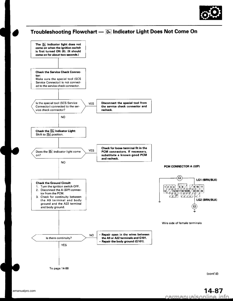
Troubleshooting Flowchart - E Indicator Light Does Not Come On
PCM CONNECTOR A {32PI
Wire side ot temale terminals
LGl IBRN/BLKI
LG2 (BRN/BLKI
(cont'd)
The E indicator light doos notcomo on whon the ignition switchis first turned ON {lll. (lt shouldcome on lor about two aaclnd!.I
Check the Sorvice Check Connec-toriMake sure the special tool 1SCSService Connector) is not connect-ed tothe service check connector,
Di3connect the spccial tool tromthe servica chock connoctor andrechsck.
ls the specialtool (SCS ServiceConnectorlconnected to the ser-vice check connector?
chock th. El Indicator Light:Shift to E position.
Ch6ck for looie terminal fit in thePCM connoctors. ll nocesssry,sub.titule a known-good PCMand rechock.
Check the Ground Circuit:1. Turn the ignition switch OFF.2. Disconnect the A {32P)connec-tor from the PCM.3. Check for continuity betweenthe A9 terminal and bodyground and tho A22 terminaland body ground.
R€pair opon in the wire3 betweenthe Ag or A22 torrninab and G101.Repair the body ground (G1011.
To page 14-88
14-87
www.emanualpro.com
Page 635 of 1395
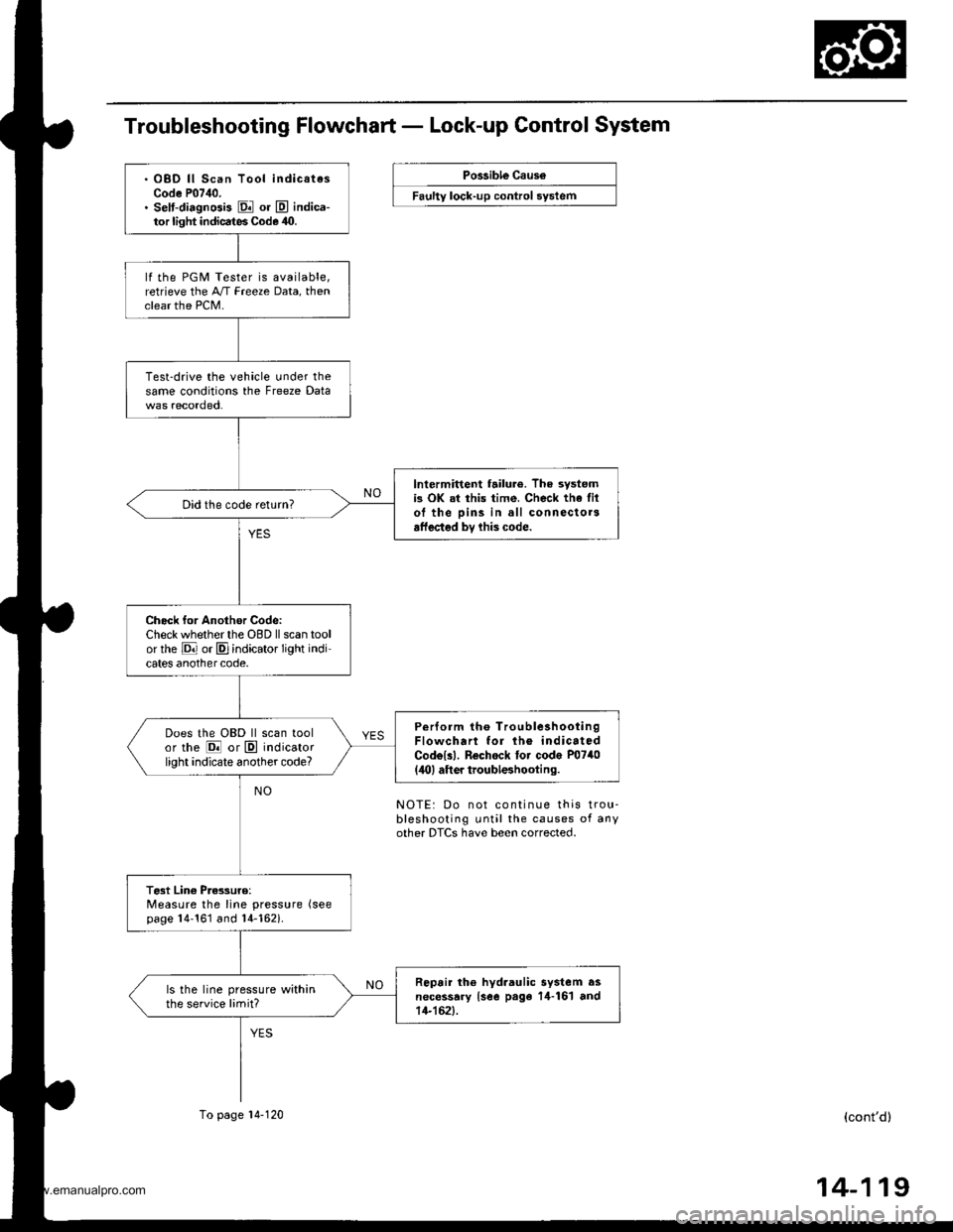
Troubleshooting Flowchart - Lock-up Control System
Possible Caus6
Faulty lock-up control system
. OBD ll Scan Tool indicatesCode P07,10.. selt-diagnGis El or E indica-tor light indicates Code 40.
lf the PGM Tester is available,retrieve the A/T Freeze Data, thenclear the PCM.
Test-drive the vehicle under thesame conditions the Freeze Data
lntermittent failur6. The systemis OK at this time, Check the filol the pins in all connectorsaffected bv lhis code.
Did the code return?
Check for Another Codc:Check whether the OBD ll scan toolor rhe E or E]indicator light indicates anothercode,
Perform tho TroubleshootingFlowchart for lh6 indicatedCodolll. Rechock tor code P0740(,lO) aft er troubleshooting.
Does the OBD ll scan toolor the @ or E indicatorlight indicate another code?
Test Lin€ Pres3uro:Measure the line pressure (see
page 14'161 and 14-162i.
Repair th6 hyd.aulic system asnecessary {see page 14-161 and14-152).
ls the line pressure withinthe service limit?
To page 14-120
NOTE: Do not continue this trou-bleshooting until the causes of anyother DTCS have been corrected.
(cont'd)
14-119
www.emanualpro.com
Page 637 of 1395
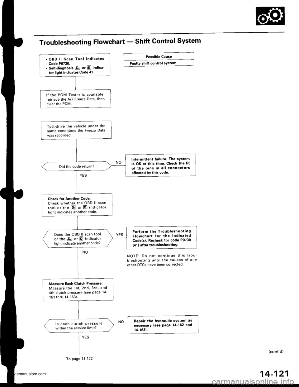
Troubleshooting Flowchart - Shift Control System
Possible Cause
Faultv shift control sYstem
NOTE: Do not continue thas trou
bleshooting until the causes of any
other DTCS have been corrected.
(cont'd)
14-121
. OBD ll Scan Tool indicates
Code P0730.. Self-diagnosis Jir or E indica-
tor light indicates Code 41.
lf the PGM Tester is available,
retrieve the AJ.I Freeze Data, then
clear the PCM.
Test-drive the vehicle under the
same conditions the Freeze Data
lntermittent failure. The system
is OK at this time. Ch€ck the fit
of the pins in all connectors
atfected by this code.
Did the code return?
Check for Another Code:
Check whether the OBD ll scan
tool or the l-Drl or E] indicator
light indicates another code.
Perlorm the TroubleshootingFlowchart for the indicaled
Codets). Recheck for code P0730
{411 6ft6r troubleshooting.
Does the OBD ll scan tool
or the Da or E indicatorlighl indicate another code?
Measure Each Clutch Pressure:
Measure the 1st, 2nd, 3rd, and
4th clutch Pressure (see Page 14
161 thru 14163).
Repair the hydraulic sYstem as
necessary (se€ page 14-162 and
14-163).
ls eac h clutch Pressurewithin the service limit?
To page 14-122
www.emanualpro.com
Page 639 of 1395
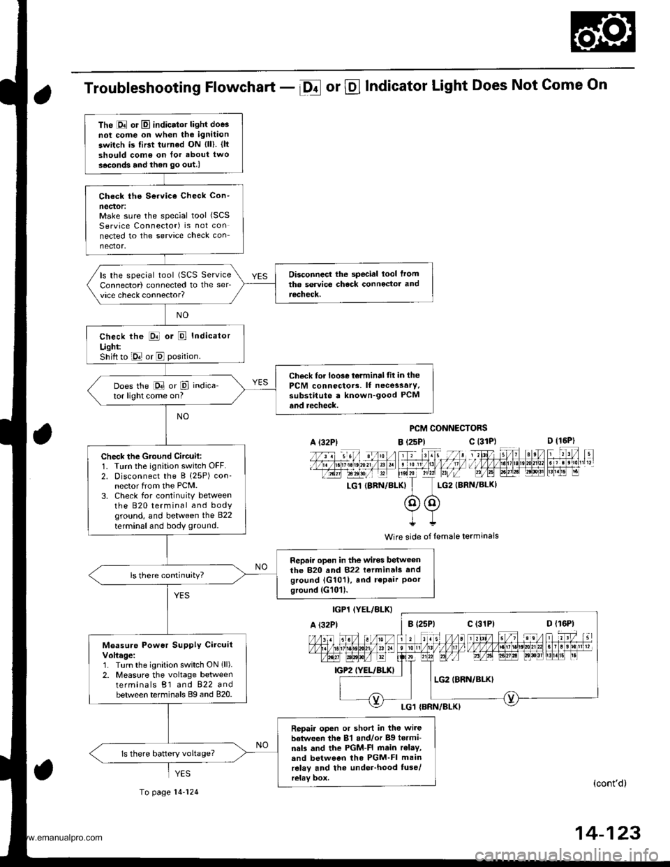
Troubleshooting Flowchart - Df or @ Indicator Light Does Not Come On
PCM CONNECTORS
B t2sPl c (31D (16P)
l*f4tr 8-
f - -- -6 3 rol ,: irr t lrpri$fe?0?r/a)1 e 'oI 13 11/ / l//|rrr I , ltelx ?r2? r,/i-T_LG1 {8RN/BI-KI I LG2 (BRN/BL()I
@@I++
Wire side of lemale terminals
(cont'd)
14-123
The E or El indicator light doe3not cofie on when the ignitaon
switch is first turned ON {ll). {ltshould como on for about two
s.cond3 and ihen go out.l
Check ths Service Check Con-
neclor:Make sure the special tool (SCS
Service Connector) is not connected to the service check connector.
Disconnecl the special lool lromtha service check connoctor andrecheck.
ls the special tool (SCS ServiceConnector) connected to the ser_vice check connector?
check the E or E Indicator
Ught:Shift to E or E position.
Check for loo3e t6lminal tit in thePCM connectors. lf necessary.substitute a known-good PCMand recheck.
Does the E or P indica-tor light come on?
Check the Gtound Circuil:1. Turn the ignition switch OFF.2. Disconnect the B (25P) con-nector from the PCM.3. Check for continuitY betweenthe 820 terminal and bodyground, and between the 822
terminal and body ground.
Repair open in the wires betweenthe 820 and 822 terminals andground {G1011, and r€Pair Poorground (G101).
ls there continuity?
Measure Power Supply CircuitVoltage:1. Turn the ignition switch ON 1ll).2. Measure the voltage betweenterminals B1 and 822 andbetween terminals Bg and 820.
Repair open or short in tho wi.ebetween the 81 and/or Bg tormi-nals and the PGM-FI main r€lay,.nd between tho PGM-FI mainrelay and the under-hood tuse/relay box.
ls there battery voltage?
A l32Plc (31P)
c (31P)
YES
To page 14-124
www.emanualpro.com
Page 737 of 1395
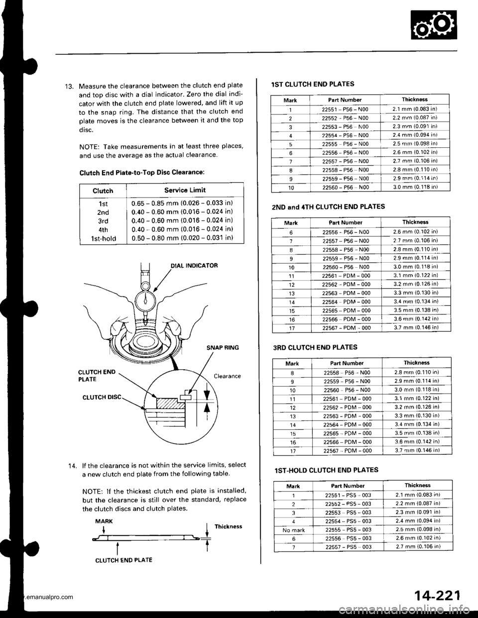
13. Measure the clearance between the clutch end plate
and top disc with a dial indicator. Zero the dial indi-
cator with the clutch end plate lowered, and lift it up
to the snap ring. The distance that the clutch end
plate moves is the clearance between it and the top
dtsc.
NOTE: Take measurements in at least three places'
and use the average as the actual clearance.
Clutch End Ptate-to-Top Disc Clearance:
ClutchService Limit
'l st
2nd
3rd
4th
lst-hold
0.65 - 0.85 mm (0.026 - 0.033 in)
0.40 - 0.60 mm (0.016 - 0.024 in)
0.40 - 0.60 mm (0.016 - 0.024 in)
0.40 - 0.60 mm (0.016 - 0.024 in)
0.50 - 0.80 mm (0.020 - 0.031 in)
SNAP RING
lf the clearance is not within the service limits, select
a new clutch end plate from the following table
NOTE: lf the thickest clutch end plate is installed,
but the clearance is still over the standard, replace
the clutch discs and clutch plates.
MARK
I I rnictness
--:--l----T
14.
CLUTCH END PLATE
14-221
lST CLUTCH END PLATES
2ND and 4TH CLUTCH END PLATES
3RD CLUTCH END PLATES
lST-HOLD CLUTCH END PLATES
MarkThicknass'I22551 P56 - N002.1 mm (0.083 in)
222552-P56-N002.2 mm (0.087 in)
322553 - P56 N002 3 mm (0.091 in)
22554-P56-NOo2.4 mm (0.094 in)
522555 P56 - N002.5 mm {0.098 in)
622556 P56 - N002 6 mm (0.102 in)
722557 - P56 N002.7 mm (0.106 in)
822558 - P56 N002.8 mm (0.110 in)
I22559 - P56 N002.9 rnm (0.114 in)
1022s60 - P56 N003.0 mm (0.118 in)
MarkParl NumberThickness
622556-P56-N002.6 mm (0.102 in)
122557 P56 - N002.7 mm (0.106 in)
822558-P56-N002.8 mm (0.110 in)
22559-P56-N002.9 mm (0.114 in)
1022560 - P56 N003.0 mm (0.118 in)'1122561 PDM - 0003.1 mm (0.122 inl
1222562 - PDM - 0003.2 mm {0.126 in)
1322563 PDM - 0003.3 mm (0.130 in)
22564 PDM - 0003.4 mm (0.134 in)
22565 PDM - 0003.5 mm (0.138 in)
22566 PDM - 0003.6 mm 10.142 in)
1722567-PDM-0003.7 mm (0.146 in)
MarkPart NumberThiclness
I22558 P56 - N002.8 mm (0.110 inl
922559 P56 - N002.9 mm (0.114 in)
1022560 P56 - N003.0 mm (0.118 in)
1122561 PD[4 - 0003.1 mm (0.122 in)
1222562 - PDM 0003.2 mm (0.126 in)
t322563-PDM-0003.3 mm (0.130 in)'1422564-PDN4-0003.4 mm (0.134 in)
1522565-PD[,l-0003.5 mm (0.138 in)
22566 PDM - 0003.6 mm (0.142 in)'t122567 - PoM - 0003.7 mm {0.146 in)
Thickness
2255r-PS5-0032.1 mm (0.083 in)
22552 - PS5- 0032.2 mm {0.087 in)
322553 PS5 - 0032.3 mm (0.091 in)
22554, PS5 - 0032.4 mm (0.094 in)
22555 PS5 - 0032.5 mm (0.098 in)
622556 PS5 - 0032.6 mm {0.102 in)
722557 - PSs 0032.7 mm (0.106 in)
www.emanualpro.com
Page 788 of 1395
Shift Gable
Adjustment
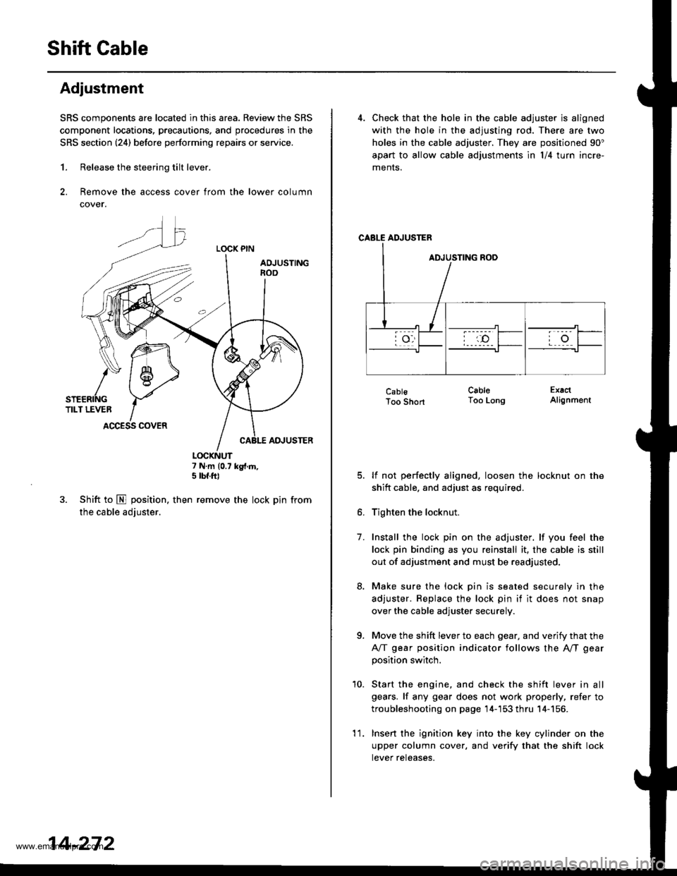
SRS components are located in this area. Review the SRS
component locations, precautions, and procedures in the
SRS section (241 before performing repairs or service.
1. Release the steering tilt lever.
2. Remove the access cover from the lower column
cover.
LOCK PIN
AOJUSTINGnoo
ADJUSTER
7 N.m (0.7 kg{.m,5 tbf.ft)
3. Shift to E position. then remove the lock pin from
the cable adjuster.
K\ffi
/* 1 6-,>
snenrftc YTILT LEVER IACCESS COVER
14-272
'l 1.
4. Check that the hole in the cable adjuster is aligned
with the hole in the adjusting rod. There are two
holes in the cable adjuster. They are positioned 90"
apart to allow cable adjustments ln l/4 turn incre-
ments.
CABLE ADJUSTER
CablsToo Short
lf not perfectly aligned, loosen the locknut on the
shitt cable. and adjust as required.
Tighten the locknut.
Install the lock pin on the adjuster. lf you feel the
lock pin binding as you reinstall it, the cable is still
out of adjustment and must be readjusted.
Make sure the lock pin is seated securely in the
adjuster. Replace the lock pin if it does not snap
over the cable adjuster securely.
Move the shift lever to each gear, and verify that the
A/T gear position indicator follows the A"/T gear
position switch.
Start the engine, and check the shift lever in all
gears. lf any gear does not work properly, refer to
troubleshooting on page 14-'153 thru 14-156.
Insert the ignition key into the key cylinder on the
upper column cover, and verify that the shift lock
tever reteases.
CableToo LongExactAlignment
7.
a
10.
www.emanualpro.com
Page 844 of 1395
Propeller Shaft
Inspection
Univarsal Joint and Boots
1. Shift the transmission to Neutral.
2. Raise the vehicle off the ground, and support it with
safety stands in the proper locations (see section 1).
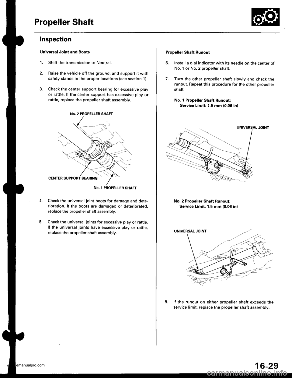
3. Check the cente. support bearing for excessive play
or rattle. It the center support has excessive play or
raftle, replace the propeller shaft assembly.
No. 1 PROPET_LER SHAFT
Check the universal joint boots for damage and dete-
rioration. lt the boots are damaged or deteriorated,
replace the propeller shaft assembly.
Check the universal joints for excessive play or rattle.
lf the universal joints have excessive play or rattle,
replace the propeller shaft assembly.
Propellor Shaft Runout
6. Install a dial indicator with its needle on the center of
No, 1 or No.2 propeller shaft.
7. Turn the other propeller shaft slowly and check the
runout. Repeat this procedure for the other propeller
shaft.
No. 1 Propeller Shaft Runout:
Service Limit: t.5 mm (0.06 in)
No. 2 Propeller Shaft Runout:
Service Limit: 1.5 mm {0.06 inl
lf the runout on either oroDeller shaft exceeds the
service limit, replac€ the propeller shaft assembly.
16-29
www.emanualpro.com
Page 935 of 1395
Front Brake Disc
Disc Runout Inspection
l.Loosen the front wheel nuts slightly, then raise the
vehicle, and make sure it is securely supported.
Remove the front wheels.
Remove the brake pads {see page 19-9).
Inspect the disc surface for damage and cracks.
Clean the disc thoroughly, and remove all .ust.
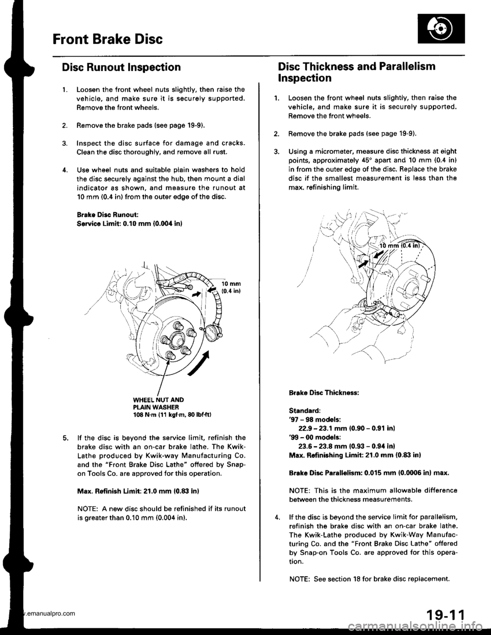
Use wheel nuts and suitable plain washers to hold
the disc securely against the hub, then mount a dial
indicator as shown, and maasure the runout at
10 mm (0.4 in) from the outer edge of the disc.
Brake Di3c Runout:
Service Limit: 0.10 mm {0.00,0 in)
WHEEL NUT ANDPLAIN WASHER108 N.m {11 kg{ m, 80 lbf.ft)
lf the disc is beyond the service limit, refinish the
brake disc with an on-car brake lathe. The Kwik-
Lathe produced by Kwik-way Manufacturing Co.
and the "Front Brake Disc Lathe" offered by Snap-
on Tools Co. are approved for this operation.
M8x. Rofinish Limit: 21.0 mm l0.8il in)
NOTE: A new disc should bs refinished if its runout
is greater than 0.10 mm (0.004 in).
Disc Thickness and Parallelism
Inspection
1.Loosen the front wheel nuts slightly, then raise the
vehicle, and make sure it is securely supported.
Remove the front wheels.
Remove the brake pads (see page 19-9).
Using a micromater, measure disc thickness at eight
points, approximately 45'apan and 10 mm (0.4 in)
in from the outer edge of the disc. Replace the brake
disc if the smallest measurement is less than the
max. refinishing limit.
Brake Disc Thickness:
Standard:'97 - 98 modsls:
22.9 -23.1mm {0.90 - 0.91 inl'99 - 00 mod€ls:
23.6 - 23.8 mm {0.93 - 0.94 in}
Max. Refinishing Limit:21.0 mm (o.txl in)
Brake Disc Parallelism: 0.015 mm {0.0006 in} max.
NOTE: This is the maximum allowable difference
between the thickness measurements,
lf the disc is beyond the service limit for parallelism,
refinish the brake disc with an on-car brake lathe.
The Kwik-Lathe produced by Kwik-Way Manufac-
turing Co. and the "Front Brake Disc Lathe" offered
by Snap-on Tools Co. are approved for this opera-
tron.
NOTE: See section 18 for brake disc replacement.
19-1 1
www.emanualpro.com
Page 950 of 1395
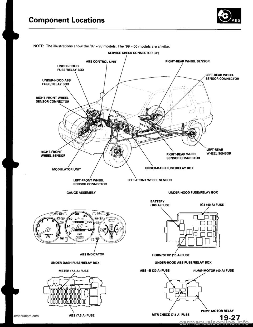
Component Locations
NOTE: The illustrations show the '97 - 98 models. The '99 - 00 models are similar.
ABS CONTROL UNITRIGHT-REAR WHEEL SENSOR
UNDER.HOOD ABSFUSE/RELAY BOX
RIGHT.FRONT WHEELSENSOR CONNECTOR
RIGHT-FRONTWHEEL SENSORRIGHT-REAB WHEELSENSOR CONNECTOR
MODULATOR UNIT
LEFT.FRONT WHEEL SENSOB
UNDER.DASH FUSE,/RELAY 8OX
UNDER.HOOO FUSE/RELAY AOX
IGl I(, AI FUSE
ABS +B 120 Al FUSEPUMP MOTOR ('II AI FUSE
HOBN/STOP I15 AI FUSE
UNDER.HOOD ABS FUSE/RELAY BOX
LEFT.FRONT WHEELSENSOE CONNECTOR
GAUGE ASSEMBLY
ABS INDICATOR
UNDER-DASH FUSE/NELAY BOX
METER {7.5 AI FUSE
MOTOR RELAY
19-27
SERVICE CHECK CONNECTOR {2PI
D!
trtrtr
[r D!
ABS {7.5 AI FUSEMTR CHECK 17.5 AI FUSE
www.emanualpro.com
Page 958 of 1395
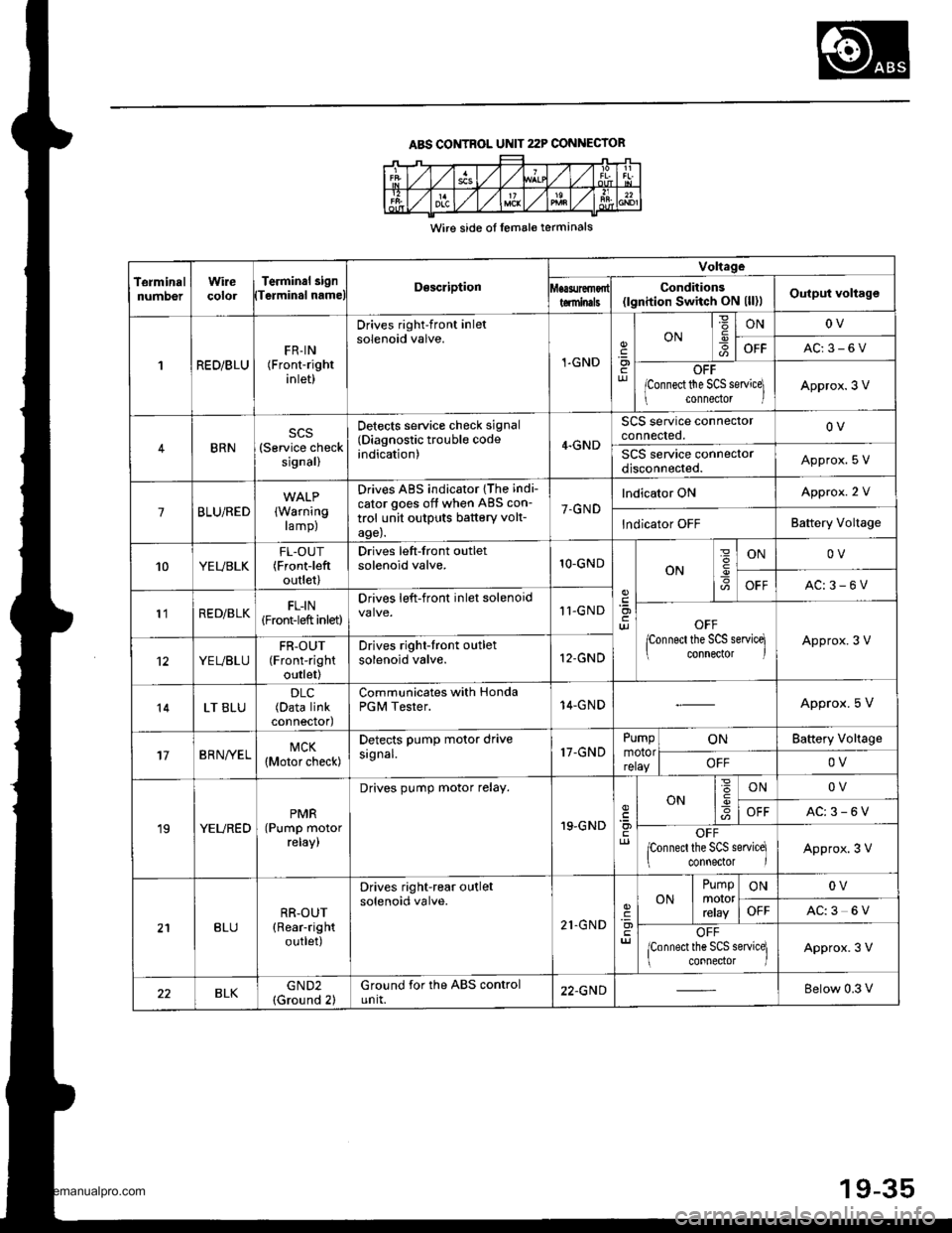
ABS CONTROL UNIT 22P CONNECIOR
Wire side ol lemale terminals
TerminalnumDerWirecolorTerminal 3i9nTerminal nameDescription
Voltage
Conditions(lgnition Switch ON (ll)lOutput voltagetominals
1RED/BLUFR-IN(Front-right
inlet)
Drives right-front inletsolenoid valve.
1-GND.9otur
ONIONOV
OFFAC:3-6V
OFF
lconnect the SCS servicel
connedor lApprox.3 V
BRN(Service checksignal)
Detects service check signal(Diagnostic trouble codeindication)4.GND
SCS service connectorconnected.OV
SCS service connectordisconnected.Approx. S V
7BLU/RED(Warning
ramp)
Drives ABS indicator {The indi-
cator goes off when ABS con-
trol unit outputs battery volt-age).
7.GND
lndicator ONApprox. 2 V
lndicator OFFBattery Voltage
10YEUBLKFL-OUT(Frontieft
outlet)
Drives left-front outletsolenoid valve.1O-GNDON
=
I
ONOV
OFFAC:3-6V
l'lRED/BLKFL-IN(Front-left inlet)
Drives left-front inlet solenoid11-GNDOFF
lconnect the SCS servicq connector lApprox.3 V
YEUBLUFR-OUT(Front-right
outlet)
Drives right-front outletsolenoid valve.12-GND
14LT BLU(Data linkconnectod
Communicates with HondaPGM Tester.14-GNDApprox. 5 V
17BRN/YELMCK(Motor check)
Detects PumP motor drivesignal.17-GNDPumpmotorrelay
ONBattery Vollage
OFFOV
19YEUREDPMR(Pump motorreray,
Drives pump motor relay.
19.GNDcl)
ON6IONOV
OFFAC:3-6V
OFFponnecl the SCS service]
connector IApprox.3 V
BLURR-OUT(Rear-right
outlet)
Drives right-rear outletsolenoid valve.
21.GND'a)
ONPumpmororrcray
ONOV
OFFAC:3 6V
OFF
lconnect the SCS service] connector lApprox.3 V
BLKGND2(Ground 2)Ground for the ABS controlunit.22.GNDBelow 0.3 V
19-35
www.emanualpro.com