Socket HONDA CR-V 1997 RD1-RD3 / 1.G Service Manual
[x] Cancel search | Manufacturer: HONDA, Model Year: 1997, Model line: CR-V, Model: HONDA CR-V 1997 RD1-RD3 / 1.GPages: 1395, PDF Size: 35.62 MB
Page 1255 of 1395
![HONDA CR-V 1997 RD1-RD3 / 1.G Service Manual
Accessory Socket
IGNITION SWITCH
Circuit Diagram
UNDER_HOOO FUSE/RELAY 8OX
o-.
l-
lJ
txt
Fffi^-.rr-.rrl 6\
t-**1*fffiT wHTBrK +*HT-137F wHr BLK
| -*T]
UNDER-DASHFUSE/RELAYBOX
YEL/GflN RED/BLK
lt
t HONDA CR-V 1997 RD1-RD3 / 1.G Service Manual
Accessory Socket
IGNITION SWITCH
Circuit Diagram
UNDER_HOOO FUSE/RELAY 8OX
o-.
l-
lJ
txt
Fffi^-.rr-.rrl 6\
t-**1*fffiT wHTBrK +*HT-137F wHr BLK
| -*T]
UNDER-DASHFUSE/RELAYBOX
YEL/GflN RED/BLK
lt
t](/img/13/5778/w960_5778-1254.png)
Accessory Socket
IGNITION SWITCH
Circuit Diagram
UNDER_HOOO FUSE/RELAY 8OX
o-.
l-
lJ
txt
Fffi^-.rr-.rrl 6\
t-'**1*fffiT wHT'BrK +*HT-137F wHr BLK
| -*T]
UNDER-DASHFUSE/RELAYBOX
YEL/GflN RED/BLK
lt
tl
tl
$Ni*" t-*r-
tl8LK 8LK
tl
ll-:a -:
G401 G40tG4A2 G4A2
J-i,_,
l ft- € l333iEi.''' 'l
I
'"*'
,*1. I
tl
ir*?:r"$
|
tlBLK 8LK
tl
lt-l
G553 G40tG4A2
IREO/GRN
(
) No.6
i{10A)
II
i ll%ti i l9:,'3
IT
YEL
I/BLK YEL/GRN YEL,
GRN
23-95
www.emanualpro.com
Page 1256 of 1395
Accessory Socket
Accessory Socket Test/Replacement
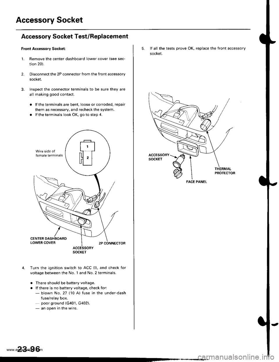
Front Accessory Socket:
1. Remove the center dashboard lower cover (see sec-
tion 20).
Disconnect the 2P connector from the front accessory
socket.
Inspect the connector terminals to be sure they are
all making good contact.
2.
lf the terminals are bent, loose or corroded, repair
them as necessary, and recheck the system.
lf the terminals look OK, go to step 4.
ACCESSORYSOCKET
Turn the ignition switch to ACC (l), and check for
voltage between the No. 1 and No. 2 terminals.
. There should be battery voltage.
. lf there is no battery voltage, check for:- blown No.27 (10 A) fuse in the under-dash
fuse/relay box.- poor ground (G401, G402).- an open in the wire.
23-96
5. If all the tests prove OK, replace the front accessory
socket.
PBOTECTOB
FACE PANEL
www.emanualpro.com
Page 1257 of 1395
Rear Accessory Socket:
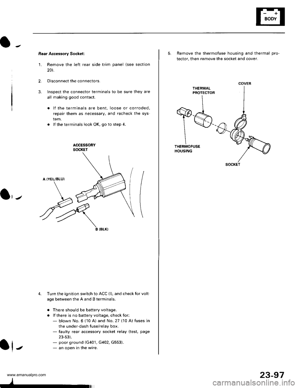
'1. Remove the left rear side trim panel {see section
20t.
2.Disconnect the connectors.
lnspect the connector terminals to be sure they are
all making good contact.
lf the terminals are bent, loose or corroded,
repair them as necessary, and recheck the sys
tem.
. lf theterminals look OK, goto step 4.
ACCESSORYSOCKET
A (YEL/8LUI
3.
\J
ryIIBLK}
4. Turn the ignition switch to ACC (l), and check tor volt
age between the A and B terminals.
o There should be battery voltage.
. lf there is no battery voltage, check for:- blown No. 6 ('10 A) and No. 27 (10 A) fuses in
the under dash fuse/relay box.- faulty rear accessory socket relay (test, page
23-53).- poor ground (G401, G402, G553).- an open in the wire.J
23-97
5. Remove the thermofuse housing and thermal pro
tector, then remove the socket and cover.
THEEMALPROTECTOR
T$THERMOFUSEHOUSING
COVER
SOCKET
www.emanualpro.com
Page 1278 of 1395
Wipers/Washers
Rear Window Wiper Gontrol Unit lnput Test -'97 Model
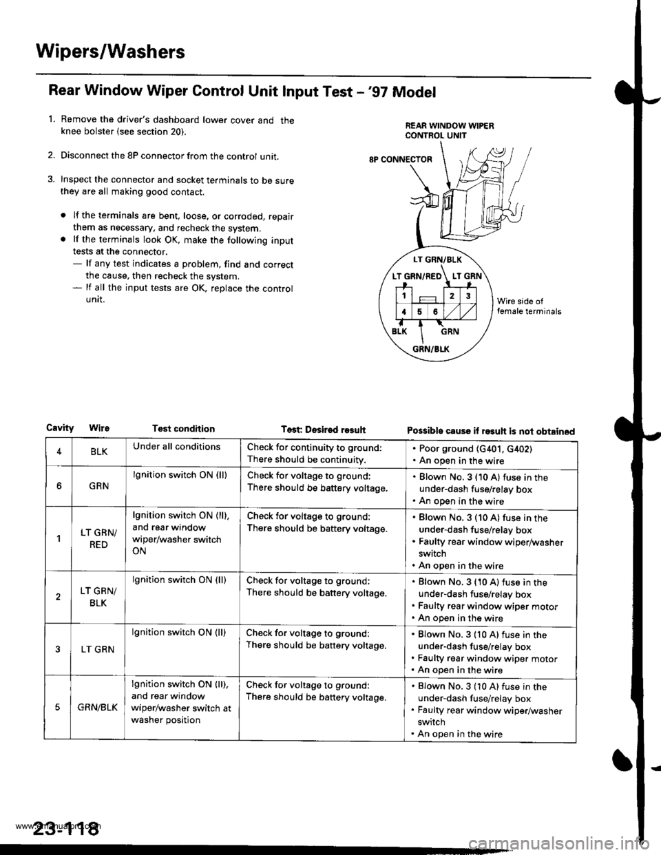
Remove the driver's dashboard lower cover and theknee bolster {see section 20).
Disconnect the 8P connector from the control unit.
Inspect the connector and socket terminals to be surethey are all making good contact.
a lf the terminals are bent, loose, or corroded, repair
them as necessary. and recheck the system.. lf the terminals look OK, make the following input
tests at the connector.- lf any test indicates a problem, find and correct
the cause, then recheck the system.- lf all the input tests are OK, replace the control
UNII.
1.
LT GRN/BLK
T GRN/RED LT
12
16
GRN/BLK
8P CONNECTOF
CavityTest condhion Test Desir€d r93uhPossible cause il rasuh is not obtained
4BLKUnder all conditionsCheck for continuity to ground:
There should be continuity.
. Poor ground (G401, c402). An open in the wire
GRN
lgnition switch ON (lllCheck for voltage to ground;
There should be battery voltage.
Blown No. 3 (10 A) fuse in the
under-dash fuse/relay box
An open in the wire
'lLT GRN/
RED
lgnition switch ON ( ll),
and rear window
wiper/washer switch
ON
Check for voltage to ground:
There should be battery voltage.
Blown No. 3 (10 A) fuse in the
under-dash fuse/relay box
Faulty rear window wiper/washer
switch
An open in the wire
LT GRN/
BLK
lgnition switch ON (lllCheck for voltage to ground;
There should be battery voltage.
Blown No. 3 {10 A) fuse in the
under-dash fuse/relay box
Faulty rear window wiper motor
An open in the wire
LT GRN
lgnition switch ON (ll)Check for voltage to ground:
There should be battery voltage.
Blown No.3 {10 A)fuse in the
under-dash fuse/relay box
Faulty rgar window wiper motorAn open in the wire
5GRN/BLK
lgnition switch ON lll),
and rear window
wiper/washer switch at
washer position
Check for voltage to ground:
There should be battery voltage.
Blown No.3 (10 A) fuse in the
under-dash fuse/relay box
Faulty rear window wiper/washer
switch
An open in the wire
23-118
www.emanualpro.com
Page 1286 of 1395
Power Door Locks
Gontrol Unit Input Test
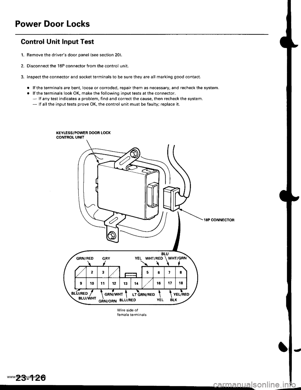
1. Remove the driver's door panel (see section 20).
2. Disconnect the 18P connector from the control unit.
3. lnspect the connector and socket terminals to be sure they are all marking good contact.
. lf the terminals are bent, loose orcorroded, repairthem as necessary, and recheck the system.
. lf the terminals look OK, make the following input tests at the connector.- lf any test indicates a problem, find and correct the cause, then recheck the system.- lf all the input tests prove OK, the control unit must be faulty; replace it.
BLUGRN/BED GRY YEL WHT/REO WHT/GRN
723,/58
101t12 1131416171E
GRN/WHT I LT
18P CONNECTON
female terminals
23-126
www.emanualpro.com
Page 1294 of 1395
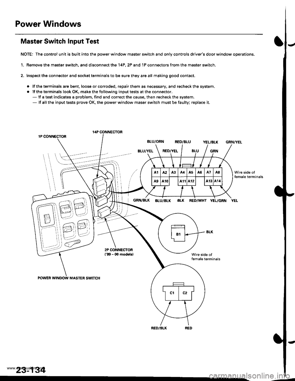
Power Windows
Master Switch Input Test
NOTE: The control unit is built into the power window master switch and only controls driver's door window operations.
1. Remove the master switch, and disconnect the 14P,2? and 1P connectors from the master switch.
2. Inspect the connector and socket terminals to be sure they are all making good contact.
. lf the terminals are bent, loose or corroded, repair them as necessary, and recheck the system,
. lf the terminals look OK, make the following input tests at the connector.- lf a test indicates a problem, find and correct the cause, then recheck the system.- lf all the input tests prove OK, the power window maser switch must be faulty; replace it.
1P CONNECTOR
BLU/ORN RED/BLUYEL/BLK
BLU/YEL RED/YELGRN
GRN/YEL
POWER WINDOW MASTEB SWITCH
GRN/BLK aLu/BLK BLK RED/WHT YEL/GRN YEL
Wire side offemale terminals
RED/BLK
lirP CONNECTOR
23-134
Wire side oIfemale terminals
.-
www.emanualpro.com