Socket HONDA CR-V 1997 RD1-RD3 / 1.G User Guide
[x] Cancel search | Manufacturer: HONDA, Model Year: 1997, Model line: CR-V, Model: HONDA CR-V 1997 RD1-RD3 / 1.GPages: 1395, PDF Size: 35.62 MB
Page 1023 of 1395
Interior Trim
@wt we@M
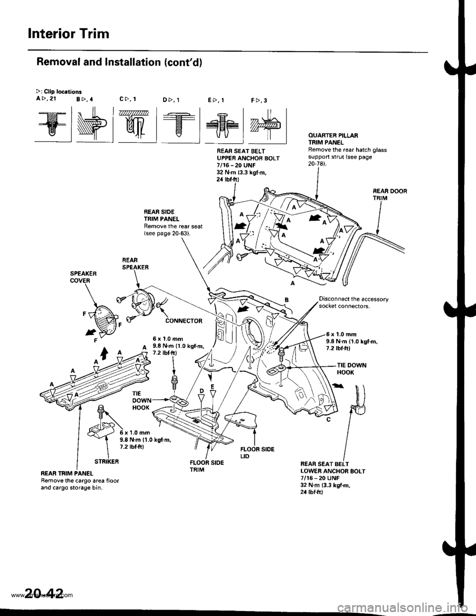
REAR SIOETRIM PANELRemove the reat seat(see page 20-63).
FCONNECTOR
2
OUARTER PILLARTNIM PANELRemove the rear hatch glasssupport strut (see page20-741.
Removal and Installation (cont'd)
>i Clip loc.tionsa>,21B>,4c>, 1E>. !F >,3D>, 1
Disconnect the accessorysocket connectors,
9.8 N.m (1.0 kgf.m,1.2lbt-lrl
5x1.0mm6x1.0mm9.8 N.m (1.0 kgtm,7.2 tbf ftl
TIE DOWNHOOK
6x1.0mm
TIEoowNHOOK
v
O\A
D
REAR SEAT BELTLOWER ANCHOR EOLT7/16 - 20 UNF32 N.m {3.3 kgt.m,24 tbl.frl
9.8 N.m (1.0 kgt m,7.2 tbf.ft)
REAR TRIM PANELRemove the cargo area floorand cargo slorage bin.
20-42
REAN SEAT BELTUPPER ANCHOR BOLT7/16-20 UNF32 N.m {3.3 kgt.m,24 rbt.ft)
REAR DOOR
REAR
ffi
STRIKER
www.emanualpro.com
Page 1031 of 1395
Dashboard
Center Dashboard Lower Gover
Removal and Installation
SRS components are located in this area. Review the SRS
component locations, precautions, and procedures in the
SRS section {24) before performing repairs or service
CAUTION:
. Wh€n prying with a flat-tip screwdrivet, wrap it with
protective tap€, and apply proteclive tape around the
rslated parts to prevenl damage.
. Put on glovgs to protect your hands.
NOTE: Take care not to scratch the dashboard and related
oarts.
1. Remove:
. Driver's dashboard lower cover (see page 20-48)
. Glove box (see page 20-49)
. Center pocket (AVT model. see page 20-49)
. Center console (M/f model, see page 20-41l,
. Center upper pocket (M/T model, see page 2O-47J
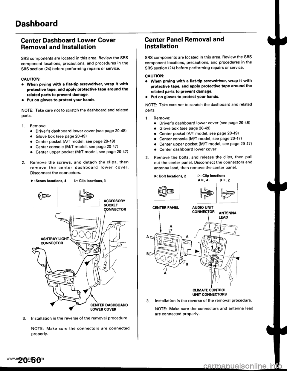
2. Remove the screws, and detach the clips. then
remove the center dashboard lower cover.
Disconnect the connectors.
>: Screw locationa,.a
I
6br" I-l
3. Installation is the reverse of the removal procedure-
NOTE: Make sure the connectors are connected
properly.
20-50
>: Clip loc.tion6,3
I5
\"P I AccEssoRyI socKET
Center Panel Removal and
lnstallation
SRS components are located in this area. Review the SRS
comDonent locations, precautions, and procedures in the
SRS section (24) before performing repairs or servace.
CAUTION:
. When prying with a flat-tip screwdriver, wrap it with
protective tape, and apply protective tape around the
relatgd parts to prevent damage.
. Put on gloves to protect your hands.
NOTE: Take care not to scratch the dashboard and related
parts.
1. Remove:
. Driver's dashboard lower cover (see page 20-48)
. Glove box (see page 20-49)
. Center pocket (A,/T model, see page 20-49)
. Center console (M/T model, see page 20-47)
. Center upper pocket {M/T model, see page 20-47)
. Center dashboard lower cover
2. Remove the bolts, and release the clips. then pull
out the center panel. Disconnect the connectors and
antenna lead. then remove the center panel.
CLIMATE CONTBOLUNIT CONNECTORS
3. Installation is the reverse of the removal procedure.
NOTE: Make sure the connectors and antenna lead
are connected proPerly.
>: Clip location3A >,4 B>,2
tt.t !^ t u . I\lJS>,, \>ryI is I r-,/'
AUOIO UNIT
>: Bolt locations,2
(8NED L-l
CENTER PANEL
www.emanualpro.com
Page 1109 of 1395
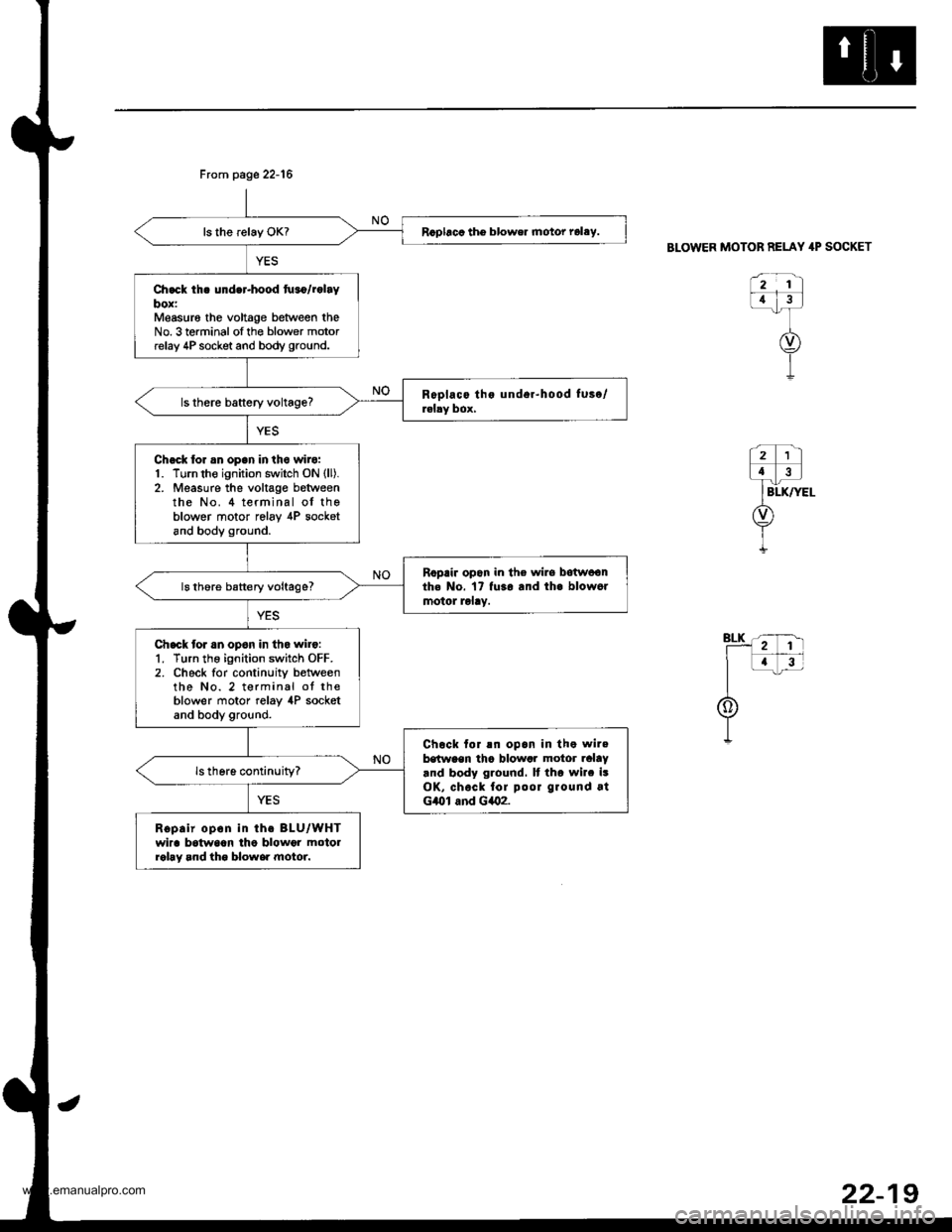
Rcpbcc tho blower motor rolay.
Ch.ck th. under-hood tu.o/rolaybox:Measur6 the voltage between theNo. 3 terminal ofthe blower motorrelay 4P socket and body ground.
Chack tor an open in the wilo:1. Turn the ignition switch ON (ll).
2. Measure the voltage betweenthe No. 4 terminal of theblower motor relav ,[P socketand body ground.
Ropair opon in the wirs botwoonth. No. 17 fu3o and th. blow6rmotol lolay.ls thore battery voltage?
Chack tor an opon in tho wilo:1. Turn the ignition switch OFF.2. Check for continuity betweenthe No. 2 terminal ot theblower motor relay 4P socketand body ground.
Chock tor !n opan in the wilebstween tha blowar motor ralaY.nd body ground. It tho wilc isOK, chock fol poor ground atG/Ol and G402.
Ropair opon in th. BLU/WHTwira batwaan lho blowor motolrohy and tho blowe. motor.
Frcm page 22-16
BLOWER MOTOR RELAY 4P SOCKET
922-1
www.emanualpro.com
Page 1116 of 1395
Troubleshooting
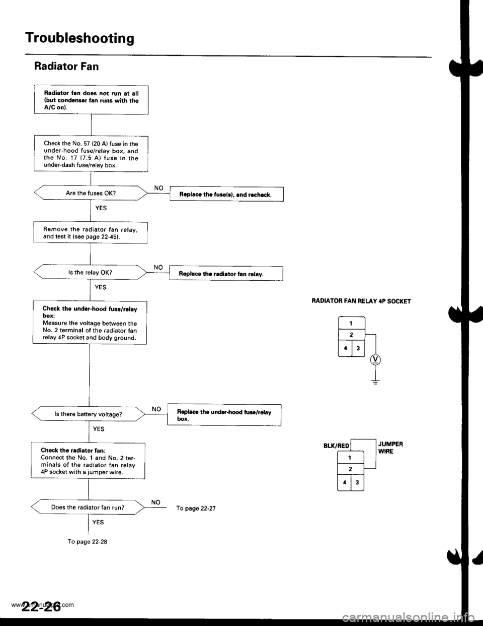
Radiator Fan
MDIATOR FAN RELAY 4P SOCKET
Radiator tan doos not run at sll(but condonser fsn runs with theA/C onl.
Check rhe No. 57 (20 Alfuse in theunderhood fuse/relay box, andthe No. 17 17.5 A) luse in the0nder-dash fuserelay box.
R.pl.c. th. fur€|.l, .nd r.chack.
Remove the radiator fan r6lay,and test it {see page 22-45).
R.pllco tha r.diator frn rehy.
Check the und.r-hood fus./r.l.ybox:Measure the voltage between theNo. 2 terminal ol the .adiator tanrelay 4P socket and body ground.
Chock the radiator tan:Connect the No. 1 and No.2 t€rminals of the radiator fan relay4P socket with a iumper wire.
Does th6 radiator fan run?
fo page 22-28
fo page 22-21
www.emanualpro.com
Page 1117 of 1395
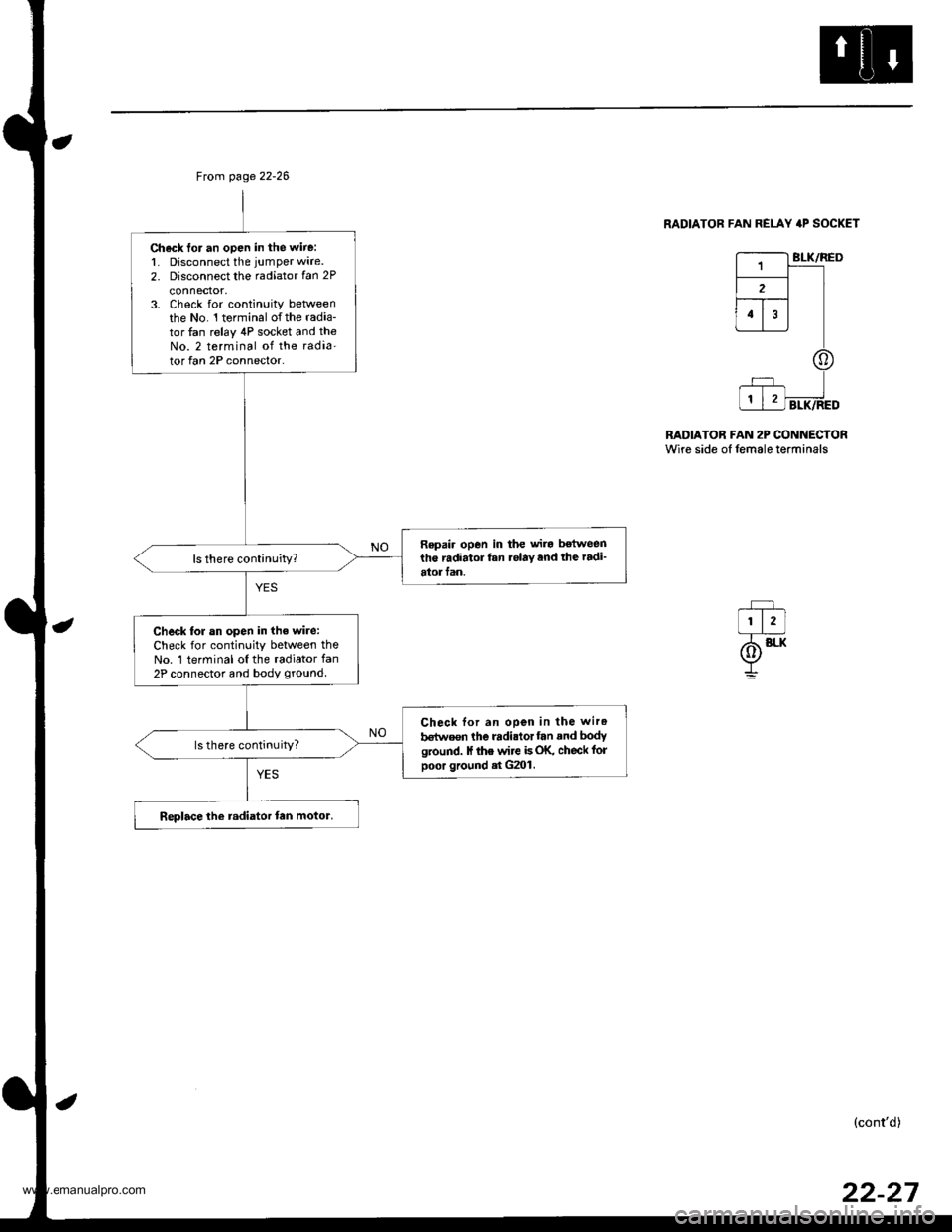
Ch6ck for an open in the wire:1. Disconnect the jumper wire.
2. Disconnect the radiator fan 2P
3. Check for continuity beNveenthe No. l terminal o{the radia-tor fan relay 4P socket and theNo. 2 terminal of the radia'tor fan 2P connector-
Repai. open in the wira betweenthe radiator fan .olay ,nd the radi'atorfan.
Check lor an open in the wi.e:Check for continuity between theNo. 1 terminal oI the radiator fan2P connector and body ground.
Check lor an open in the wir.
b€turosn the radi.tor fan and bodyground. lf ihe wire b OK, check folpoor ground .t G2()l .
ls there continuity?
Replace the radiator tan motor.
Ftom page 22-26
RADIATOR FAN REI-AY 4P SOCKET
BLK/RED
RADIATOR FAN 2P CONNECTORWire side of lemale terminals
(cont'd)
www.emanualpro.com
Page 1118 of 1395
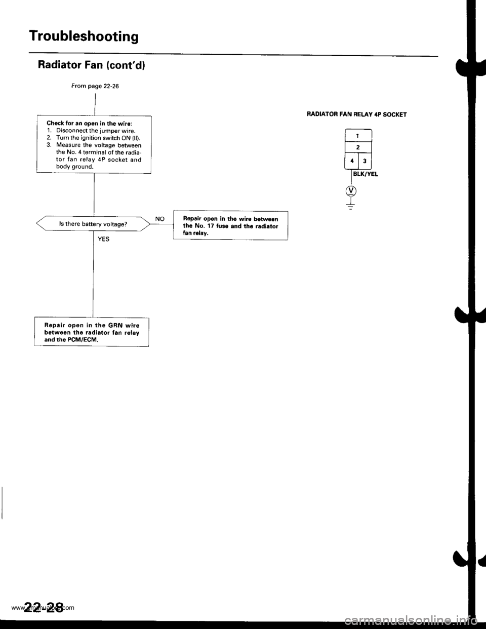
Troubleshooting
Radiator Fan (cont'dl
From page 22-26
RADIATOR FAN RELAY 4P SOCKET
BLK/YEL
1
2
a
Chock for an open in the wire:'1. Disconnect the jurnper wire.2. Turn the ignition switch ON (ll).3. lleasure the voltage betweenthe No.4terrninal of the radia-tor fan relay 4P socket andbody ground.
R€pair open in th6 wire botwoonthe No. 17 fuso and the radiatolfan .elsy.
ls there battery voltage?
Rep.ir open in the GRN wirebotw€en lhe radiator tan relayand the PCM/ECM.
22-28
www.emanualpro.com
Page 1119 of 1395
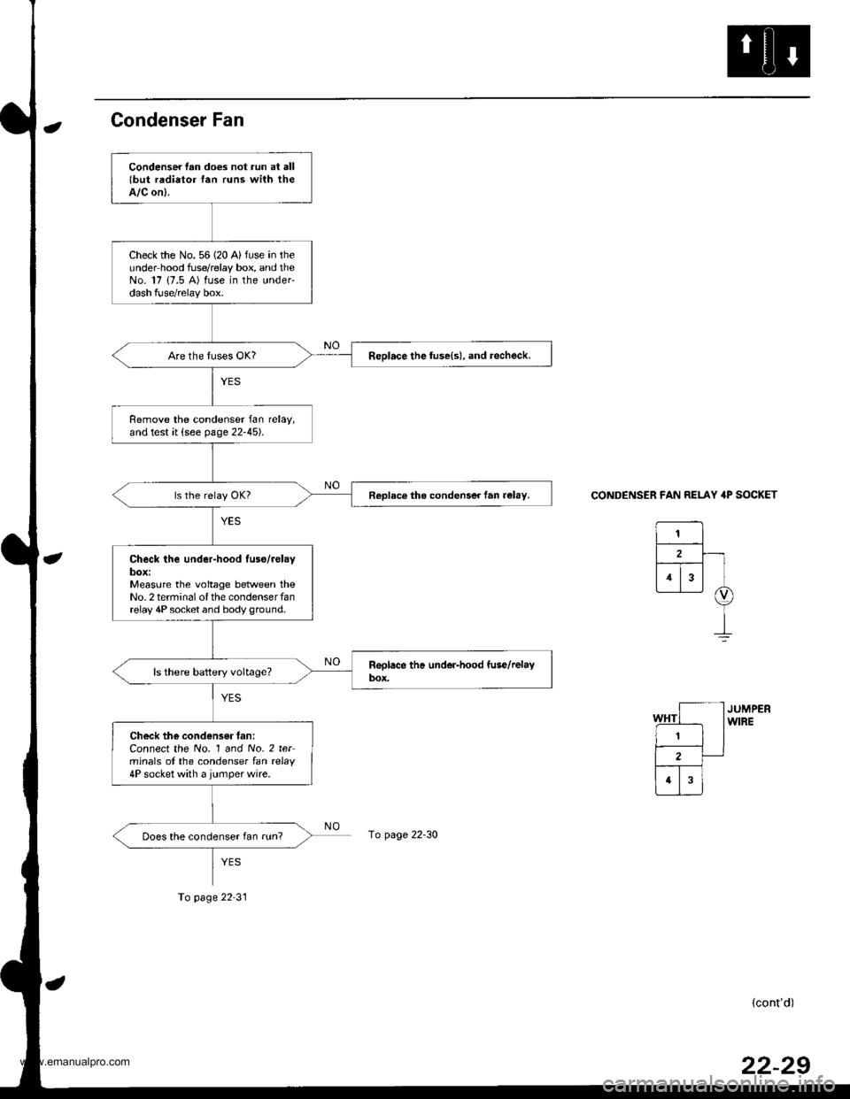
Condenser Fan
CONDENSER FAN RELAY 4P SOCKET
(cont'd)
Condenser lan does not run at alllbut radiator fan runs with theA/C on).
Check the No. 56 (20 A) fuse in theunder hood fuse/relay box, and theNo. 17 {7.5 A) fuse in the under-dash fuse/relay box.
Replace the luse(s), and .echeck.
Remove the condenser fan relay,and test it (see page 22-45).
Replace the condenser fan r€lay.
Check the under-hood luso/relaybox:Measure the voltage between theNo.2 terminal of the condenserfanrelay 4P socket and body ground.
Check the condensff fan:Connect the No. 1 and No. 2 terminals of the condenser lan rclay4P socket with a jumperwire.
Does the condenser fan run?page 22-30
To page 22 31
22-29
www.emanualpro.com
Page 1120 of 1395
![HONDA CR-V 1997 RD1-RD3 / 1.G User Guide
Troubleshooting
Condenser Fan {contd)
CONDENSER FAN RELAY 4P SOCKET
r---------t wHT
lr_f__l12 | |
fT;.] |I/Or\j/
I
G
CONDENSER FAN 2P CONNECTORWire side ol temale torminals
-r+-,.12
TBtK
@
!
Chock f HONDA CR-V 1997 RD1-RD3 / 1.G User Guide
Troubleshooting
Condenser Fan {contd)
CONDENSER FAN RELAY 4P SOCKET
r---------t wHT
lr_f__l12 | |
fT;.] |I/Or\j/
I
G
CONDENSER FAN 2P CONNECTORWire side ol temale torminals
-r+-,.12
TBtK
@
!
Chock f](/img/13/5778/w960_5778-1119.png)
Troubleshooting
Condenser Fan {cont'd)
CONDENSER FAN RELAY 4P SOCKET
r---------t wHT
lr_f__l12 | |
fT;.] |I/Or\j/
I
G
CONDENSER FAN 2P CONNECTORWire side ol temale torminals
-r+-,.12
TBtK
@
!
Chock for an open in the wire:'1. Disconnect the iumper wire.2. Disconnect the condenser fan2P connector.3. Check for continuity betweenthe No. 1 terminal of the con,denser fan relay 4P socket andthe No. 2 terminal of the con-denser fan 2P connector.
Ropair open in the wire betwoenth€ condenser fan rslay and thecondenser tan.
ls there continuity?
Chech tor an open in the wire:Check for continuity between theNo. I terminal of the condenserfan 2P connector and bodyground.
Check for an open in thg wirebetween the condenser fan andbody ground. lf the wiro is OK.check tor poor ground .t G202.
Replace tho condenser tan motor.
22-30
www.emanualpro.com
Page 1121 of 1395
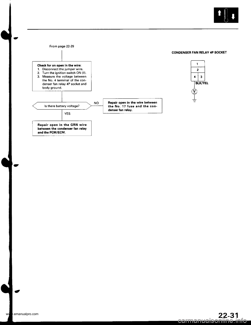
Chock for an open in the wiro:1. Disconnect the iumper wire.2. Turn the ignition switch ON (ll).
3. Measure the voltage betweenthe No. 4 terminal oI the con-denser fan relay 4P socket andbody ground.
Repair opcn in tho wire betwoonthe No. 17 tuse and the con-densea fan relay,
Repair open in the GRN wirob6tw6en the cond.nser lan relayand rhe PcM/EcM,
Ftorn page 22-29
CONDENSER FAN RELAY 4P SOCKET
22-31
www.emanualpro.com
Page 1123 of 1395
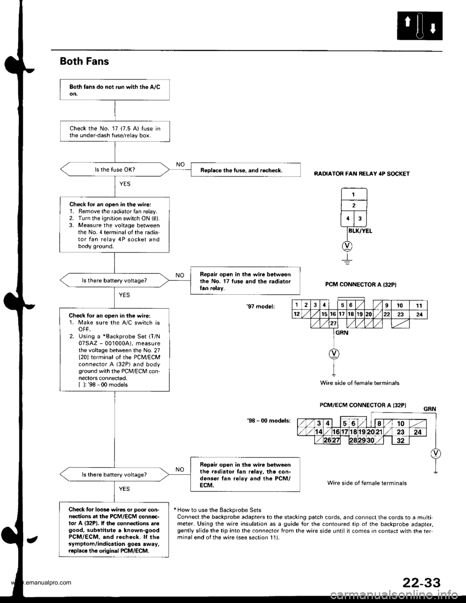
Both Fans
RADIATOR FAN RELAY 'P SOCKET
BLK/YEL
PCM CONNECTOR A I32PI
'9? model:
PCM/ECM CONNECTOR A (32PI
'98 - 0O mod6ls:
Wire side of female terminals
* How to use the Backprobe SetsConnect the backprobe adapters to the stacking patch cords, and connect the cords to a multimeter. Using the wire insulation as a guide for the contoured tip of the backprobe adapter,gently slide the tip into the connector from the wire side until it comes in contact with the terminal end ofthe ware {see section l1).
Check the No. 17 (7.5 A) tuse inthe under-dash fuse/relay box.
Reolace the tuse. and recheck.
Check for an op€n in the wire:1. Remove the radiator fan relay.2. TLrrn the ignition switch ON (ll).
3. Measure the voltage betweenthe No.4 terminalofthe radiator fan relay 4P socket andbody ground.
Repair open in the wire betweenlhe No. 17 luse and the radiatortan relay.
Check for an open in the wire:1. Make sure the A/C switch isOFF.2. Using a *Backprobe Set {T/N07SAZ - 001000A), measurethe voltage between the No. 27I20l terminal ol the PCM/ECMconnector A (32P) and bodyground with the PCM/ECM con-nectors connected.[ ]: '98 - 00 models
Repair open in the wire b€tweenthe.adiator fan ralav, the con-denser tan rolay and the PCM/ECM.
Check tor loose wires or poor con-nodions at the PCM/ECM connoc-tor A (32P1. lf the connections arcgood, substitute a known-goodPCM/ECM, and recheck. It thesymptom/indicalion goes away,r.plrce the original PCM/ECM.
1
2
1
12461011
12t5t61718r9222321
GRN
Wire side oI female terminals
22-33
www.emanualpro.com