Socket HONDA CR-V 1997 RD1-RD3 / 1.G Owner's Manual
[x] Cancel search | Manufacturer: HONDA, Model Year: 1997, Model line: CR-V, Model: HONDA CR-V 1997 RD1-RD3 / 1.GPages: 1395, PDF Size: 35.62 MB
Page 1124 of 1395
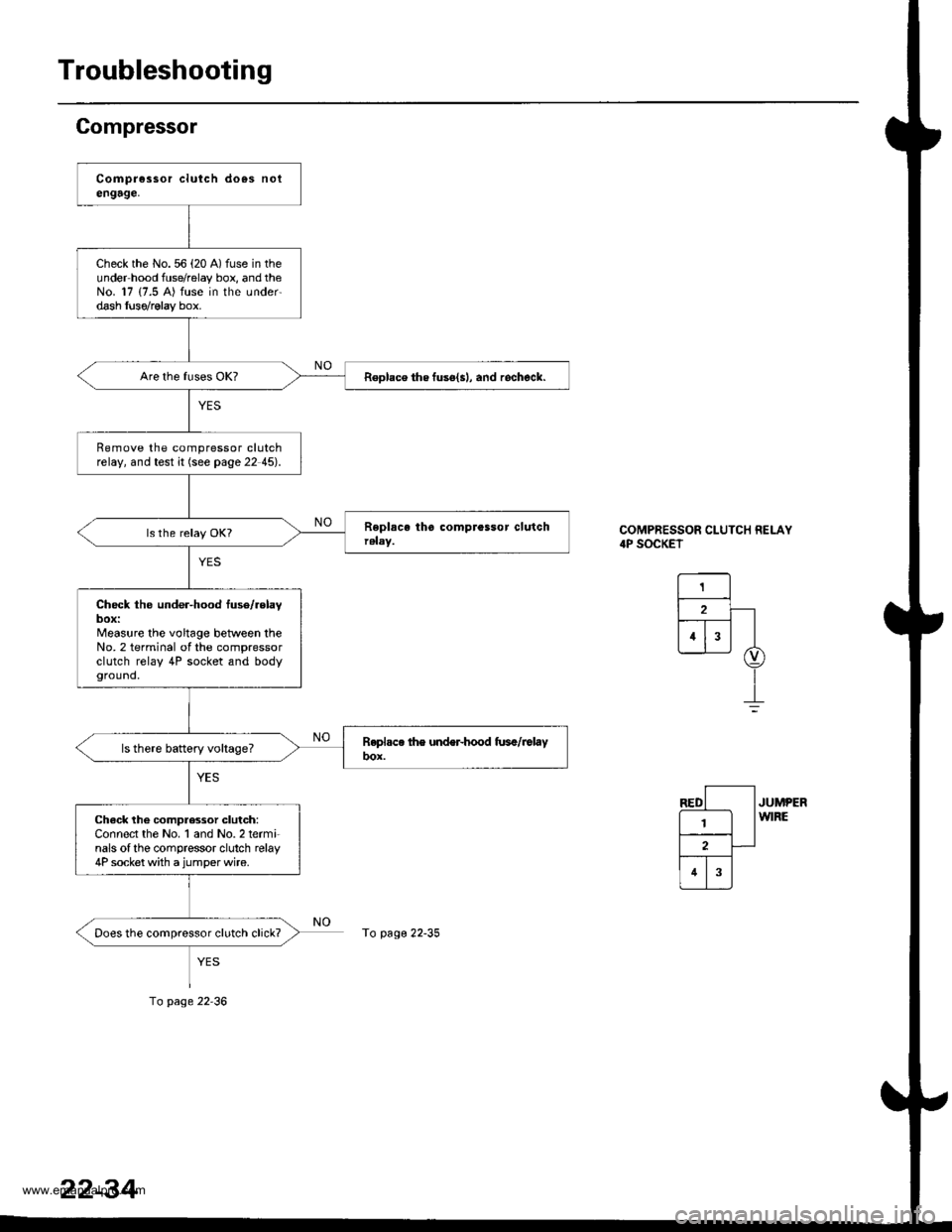
Troubleshooting
To page 22-35
Check the No. 56 (20 A) fuse in theunder hood fuse/relay box, and theNo. 17 (7.5 A) fuse in the underdash luso/rglay box.
Replace the fuso(sl, and r6check.
Remove the compressor clutchrelay, and test it (see page 22 45).
Check the under-hood fuse/relayDOX:Measure the voltage between theNo. 2 terminal of the compressorclutch relay 4P socket and bodyground,
Chack lhe complessor clutch:Connect the No. 1 and No. 2 termi-nals ofthe comoressor clutch relav4P socket with a jumper wire.
Does the comprossor clutch click?
22-34
To page 22-36
www.emanualpro.com
Page 1125 of 1395
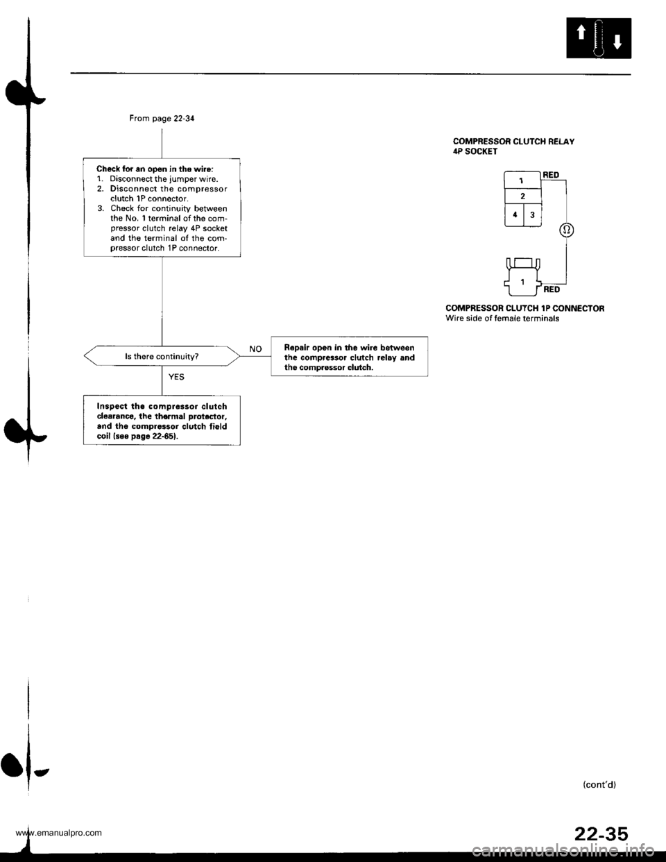
COMPRESSOR CLUTCH RELAYilP SOCKET
COMPRESSOR CLUYCH lP CONNECTORWire side of lemale terminals
-_-l RED
tr-=--l II
I.TT
@
I
$"f Ii 1 __---.1
1___J.RED
I
I
+
Ftom page 22-34
Check for an open in the wire:1. Disconnect the jumper wire.2. Disconnect the compressorclutch 1P connoctor.3. Check for continuity betweenthe No. 1 terminal of the com-pressor clutch relay 4P socketand the terminal ol the com-pressor clutch 1P connector.
Repair open in the wire betweenthe comp.e3sor clutch relay andthe comprsssor clutch.
Inspect tha compreslor clutchclearanco, the thormal protector,
and ths comDrg$or clutch tioldcoil lsee page 22-65).
I
I
.l-(cont'd)
www.emanualpro.com
Page 1126 of 1395
Troubleshooting
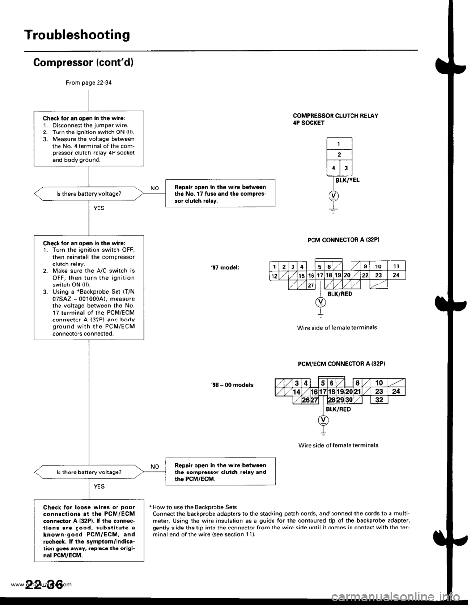
Compressor (cont'dl
COMPRESSOR CLUTCH RELAY4P SOCKET
1
2
43
BLK/YEL
PCM CONNECTOB A I32P)
'97 model:
Wire side of female terminals
PCM/ECM CONNECTOR A {32P}
38 - 00 models:
Wire side of {em6le terminals
* How to use the BackDrobe SetsConnect the backprobe adapters to the stacking patch cords, and connect the cords to a multi-meter. Using the wire insulation as a guide for the contoured tip ot the backprobe adapter,gently slide the tip into the connector trom the wire side until it comes in contact with the teFminalend o{the wire {see section l1).
Frcm page 22-34
Ch6ck for an open in the wire:1. Disconnect the jumper wire.2. Turn the ignition switch ON (ll).
3, Measure the voltage betweenthe No. 4 terminal ot the com'pressor clutch relay 4P socketand body ground.
Repair op.n in the wire betweenthe No. l7 fu3e and the compres-sor clutch ielay.
Check for an opon in the wire:1. Turn the ignition switch OFF,then reinstall the compressorclutch relay.2. Make sure the A"/C switch isOFF, then turn the ignitionswitch ON (ll).
3. Using a *Backprobe Set (T/N
07SAZ - 001000A), measurethe voltage between the No.17 terminal ol the PCM/ECMconnector A (32P) and bodyground with the PC M/ECMconnectors connected,
Repair open in lhe wire betwoonthe compressor clutch r6lay andthe PCM/ECM.
Check tor loose wires or Doorconnections at the PCM,/ECMconnecto. A {32P1. lf the connec-tions are good, sub3titute aknown-good PCM/ECM, androcheck. lf the symptom/indica-tion goas away, replac€ the origi-nal PCM/ECM.
126I1011
12151617'181S222321
BLK/RED
22-36
www.emanualpro.com
Page 1161 of 1395

Body Electrical
Speciaf Toofs ,...,..,.............-.23-2
Troubleshooting
Tips and Precautions ......,.,..........,.................. 23-3
Five-step Troubleshooting ........,.,.,...,,.,......... 23-5
Wire Color Codes ...,....,.. 23-5
Relay and Control Unit Locations
Engine Compartment ..,.,......,......................... 23-6
Dashboard ,.,.,..............-.- 23-7
Door ....................... .........23-10
Index to Cilcuits and Sysiems
Accessory Socket .. ,....,.,..,.,. 23-95*Airbags ................ .,....,. Sestion 24
Air Conditioning ,.,.,.... Section 22
Alternator ................... Section 4
Anti-lock Brake System {ABSI ................... Section 19'A/T Gear Position Indicator ....................... Section 1,1
Automatic Transmission System ...........,.. Section 14
Battery ................... ..............23-50
Blower Controls .,...,.,, Section 22
Charging System ....... Seqtion il
Clock -'98 Model ................ 23-98
Connector ldentification and Wire HarnessRouting .................. ......... 23.11
Cruise Control ............ Ssction 4
Dash Lights Brightness Contlo||er ..................... 23-90
Fan Conlrols ...,......,.... Section 10
Fuel Pump ,..,.,...,....,.... Section 11
Fuses...................... .,,.,.,.,.,,.,23-40*Gauges
Circuit Diagram ......-....-..23-58
Fuel Gauge .....,.,..... Section 11
Speedometer ..,..........,... 23-56
Ground Distribution ,....,.,...23-46
Hatch Glsss ODenor .........................,.,.,.,.,..,.,.,.,,. 23-121
Heater Controls .-........ Soction 21*Horns.,...,..,.,.,....... ................23"104*fgnition Switch ,,.,.,..,.,.,,.,.,.,23-51
lgnition Key Light System -'97 Mod6l .............. 23.88
-+
BODY
www.emanualpro.com
Page 1170 of 1395
Relay and Control Unit Locations
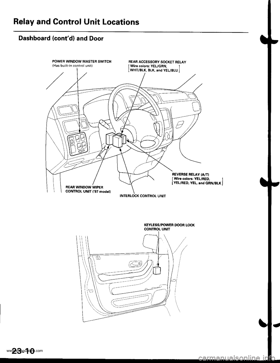
Dashboard (cont'd) and Door
REAR ACCESSORY SOCKET RELAYI Wire colors: YEL/GRN, JIWHT/BLK. BLK, .nd YEL/BLU l
REVERSE RELAY {A/TII Wire colonr YEI-/RED, IIYEL/RED, YEL, .nd GRN/BLK IREAR WINDOW WIPERCONTROL UNIT 137 mod.ll
KEYIISS/POWER DOOR L(rcKCONTROL UNIT
INTERLOCX CONTROL UNIT
23-10
www.emanualpro.com
Page 1180 of 1395

Connector ldentification and Wire Harness Routing
Main Wire Harn€ss (left side of dash and floor branchesl {cont,dl
c401
c402
c403
c404
c404
c405
c406
c407
c408
c409
c410
c410
c411
c412
c413
c413
c414
c415
c416
c416
c417
c418
c419
c420
c420
c421
c422
c423
c424
c425
c42A
c426
c437
c438
c438
c439
c440
c441c442
5
20
20
24
't4
8
5
3
12
10'1
18
20'18
10
15
1
4
8
5
5
22
Behind left kick panel
Behind left kick panel
Behind left kick panel
Behind left kick panel
Behind left kick panel
Under left side of dashUnder left side of dashUnder left side of dashUnder left side of dashUnder left side of dashUnder left side of dashUnder left side of dash
Under left side of dashUnder left side of dashUnder left side of dash
Under left side of dash
Under left side of dashUnder left side of dashUnder left side of dashUnder left side of dashUnder left side of dashUnder left side of dashUnder left side of dashUnder left side of dash
Under left side of dashUnder left side of dashUnder left side of dashUnder middle of dashUnder middle of dashUnder middle of dashUnder middle of dashUnder middle of dash
Under left side of dashUnder left side of dash
Under left side of dashUnder left side of dashUnder left side of dashUnder left side of dashUnder left side of dash
Under left side of dash
Under left side of dashUnder left side of dashUnder left side of dashUnder left side of dash
Starter cut relay
Horn relay
Left side wire harness (C558)
Left side wire harness (C559)
Left side wire harness (C559)
Cruise control unitDaytime running lights control unitDaytime running lights control unitlgnition key light control unitInterior wire harness {C701)Cable reel
Cable reel
lgnition key switchlgnition key switch
Combination switch sub-harness {C753)
Combination switch sub-harness (C753)
SRS main harness (C803)
Dashboard wire harness (C503)
Dashboard wire harness (C501)
Dashboard wire harness {C501)Under-dash fuse/relay box (C922)
Under-dash fuse/relay box (C920)
Under-dash fuse/relay box (C919)
lntegrated control unit
Integrated control unitFront fog lights switchBrake switch
Interlock control unitReverse relay
Rear accessory socket relayRear accessory socket relayRear heated oxygen sensor sub-harness (C722)
Security control unitSecurity starter cut relay (for securityalarm system)
Junction connector (for interlock system)Security wire harnessSecurity wire harnessRear window wiper control unitCombination switch sub-harness (C760)
Combination switch sub-harness (C760)
Securlty indicatorSecurity valet switchClutch interlock switchClutch switch (for cruise control)
'97 model'98 - 00mooets
Canada
Canada'97 model
'97 model'98 - 00models
'97 - 98models'99 - 00
moqets
'97 model'98 - 00mooets
Optional
Optional
Optional
Optional
Optional'97 model
'97 - 98mooels'99 - 00models
OptionalOptional
Mfi
Mlr
Under left side of dashBody ground, via main wire harness
23-20
www.emanualpro.com
Page 1184 of 1395
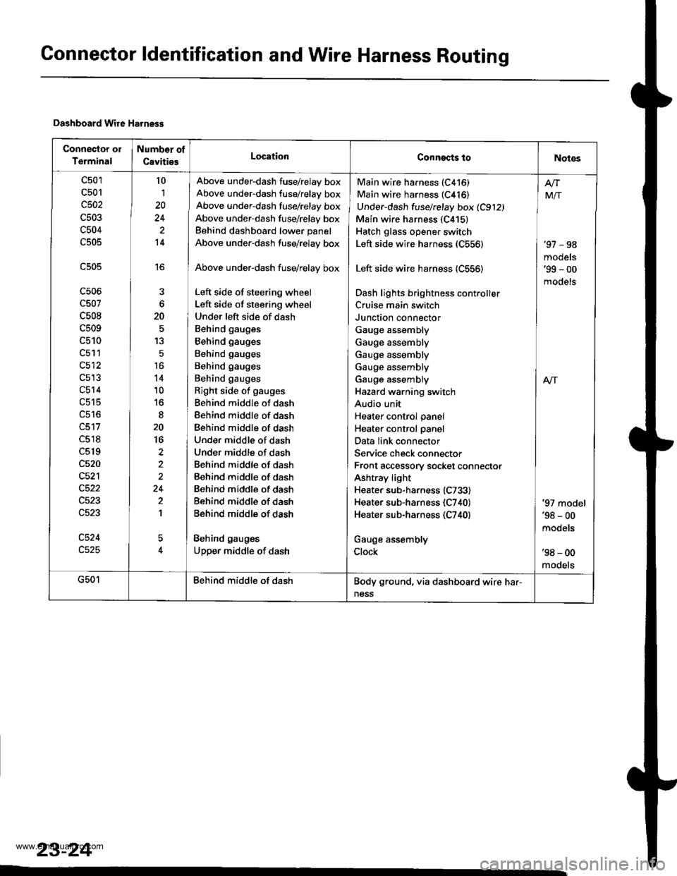
Connector ldentification and Wire Harness Routing
Dashboard Wire Harness
Connector ol
Terminal
Numb€r of
CavitiesLocationConngcts toNotes
c501
c501
c502
c503
c504
c505
c506
c507
c508
c509
c510
c511
c512
c514
c518
c519
c520
c521
c524
10
1
20
14
16
6
20
13
5
t6
14
10
to
20
16
2
24
2
1
5
Above under-dash fuse/relay box
Above under-dash fuse/relay box
Above under-dash fusehelay box
Above under-dash fuse/relay box
Behind dashboard lower panel
Above under-dash fuse/relay box
Above under-dash fuse/relay box
Left side of steering wheel
Left side of steering wheel
Under left side of dash
Behind gauges
Behind gauges
Behind gauges
Behind gauges
Behind gauges
Right side of gauges
Behind middle of dash
Behind middle of dash
Behind middle of dash
Under middle of dash
Under middle of dash
Behind middle of dash
Behind middle of dash
Behind middle of dash
Behind middle of dash
Behind middle of dash
Behind gauges
Upper middle of dash
Main wire harness (C416)
Main wire harness (C416)
Under-dash fuse/relay box 1C912)
Main wire harness (C415)
Hatch glass opener switch
Left side wire harness (C556)
Left side wire harness (C556)
Dash lights brightness cont.oller
Cruise main switch
Junction connector
Gauge assembly
Gauge assembly
Gauge assembly
Gauge assembly
Gauge assembly
Hazard warning switch
Audio unit
Heater control panel
Heater control panel
Data link connector
Service check connector
Front accessory socket connector
Ashtray light
Heater sub-harness (C733)
Heater sub-harness {C740}
Heater sub-harness (C740)
Gauge assembly
Clock
'97 - 98
models'99 - 00
models
Mir
A/r
'97 model'98 - 00
mooets
'98 - 00
models
G501Behind middle of dashBody ground, via dashboard wire har-
ness
23-24
www.emanualpro.com
Page 1186 of 1395

Connector ldentification and Wire Harness Routing
Left Side Wire Harness
Connector oI
Terminal
Number of
CavitiesLocaiionConnects toNot6s
c551
c552
c554
c556
c558
c559
c559
c560
c562
c563
c563
c564
c565
c566
c568
c569
c570
c572
c573
c57 4
c575
c576
c578
c579
c580
c581
8
16
10
14'I
14
16
20
20
24
)
1
5
1
1
6
1
2
14
1
1
6
1
6
Behind under-dash fuse/relay box
Behind under-dash fuse/relay box
Left side of steering wheel
Left side of steering wheel
Left side of steering wheel
Above under-dash fuse/relay box
Above under-dash fuse/relay box
Driver's door
Behind left kick panel
Behind left kick panel
Behind left kick panel
Left side offloor
Left quaner panel
Fueltank
On left half of rear cross beam
On left half of rear cross beam
Left quarter panel
Left quarter panel
Left quarter panel
Left quarter panel
Left quarter panel
Left quarter panel
On left half of rear cross beam
Right quarter panel
Right quarter panel
Left quarter pillar
Left side of floor
Left B-piller
Left B-piller
Behind left kick panel
Behind left kick panel
Under left side of dash
Left B-piller
Fueltank
Left side of steering wheel
Under-dash fuse/relay box (C921)
Under-dash fuse/relay box (C923)
Power mirror switch
Power window master switch
Power window master switch
Dashboard wire harness {C505)
Dashboard wire harness 1C505)
Driver's door wire harness (C661)
Main wire harness (C403)
Main wire harness (C404)
Main wire harness (C404)
Driver's seat belt switch
Left rear door switch
Fuel unit
Left rear ABS wheel sensor
Left rear ABS wheel sensor
Rear accessory socket connector {+}
Rear accessory socket connector (-)
Rear bumper wire harness 1C641)
Trailer lighting connector
Tailgate door latch switch
Left rear speaker
Right rear ABS wheel sensor
Rear wire harness (C611)
Right rea. door switch
Left taillight
Parking brake switch
Left rear door wire harness (C681)
Driver's door switch
Select unlock relay (for security alarm
system)
Junction connector (for power door
locks)
SRS main harness (C807)
Driver's seat belt tensioner
Fuel tank pressure sensor sub-harness(c645)
Power window master switch
'97 - 98
mooets'99 - 00
models
'97 model'98 - 00
models
Optional
'97 model'98 - 00
models
'98 - 00
mooets'98 - 00
models'98 - 00
mooets'99 - 00
mooets
G551
G553
Behind left kick panel
Left side ot floor
Left quarter piller
Body ground, via left side wire harness
Body ground, via left side wire harness
Body ground, via left side wire harness
23-26
www.emanualpro.com
Page 1204 of 1395

Power Distribution
Fuse
1
3
5
6
7
I
9
10
11
12
13
14
"^
RED/B LU
RED/GRN
WHT/BLK
RED/VVHT
YEUBLK
RED
GRN/BLK
BLU/BLK
YEVBLK
YEUGRN
RED
BLK/YE L
BLK/VVHT
17
7.5 A
7.5 A
BLVBLU
BLKA/EL
18
19
20
22
7.54
7.54
l0 A
10 A
YEUBLK
YEVRED
BLKAr'YHT
RED /VHT
RED/YE L
Fuse-to-Component(sl Index (numerical sequencel (cont'dl
Under-dash Fuse/Relay Box:
Capacity
10 A
10 A
10 A
10 A
20A
204
15A
204
204
7.5 A'15 A
7.5 A
7.5 A
Wire ColorCircuit{s) Protected
Not used
Not used
Rear window washer motor (via switch)
Rear window wiper control unit ('97 model)
Rear window wiper motor
Daytime running rights resister {Canada)
Right headlight {High beam}
Daytime running rights resister (Canada)
High beam indjcator light
Left headlight (High beam)
Rear accessory socket (via relay)
Left rear power window motor (via switch)
Right rear power window motor (via switch)
Distributor (ignition control module)
Front passenger's power window motor (via switch)
Driver's power window motor {via switch)
Power window master switch (power window control unit)
Turn signal/hazard relay (via switch)
PGM-FI main relay
SRS unit (VA)
Cruise control unit (via switch)
Cruise main switch indicator light
Alternator
Charging system light
ELD unit (USA)
EVAP bypass solenoid valve ('98 - 00 models)
EVAP control canister vent shut valve ('98 - 00 models)
EVAP purge control solenoid valve
Primary HO2S
Secondary H02S
VSS
ABS control unit
Option connector (lG2)
Ay'C compressor clutch relay
Blower motor high relay
Blower motor relay
Condenser fan relay
Heater control panel
Left power mirror actuators (via switch)
Mode control motor
Radiator fan relay
Recirculation control motor
Right power mirror actuators (via switch)
Daytime running lights control unit (Canada)
Back-up lights
Reverse relay (A"/T)
Daytime running lights control unit (Canada)
Right headlight (Low beam)
Left headlight (Low beam)
23-44
www.emanualpro.com
Page 1205 of 1395
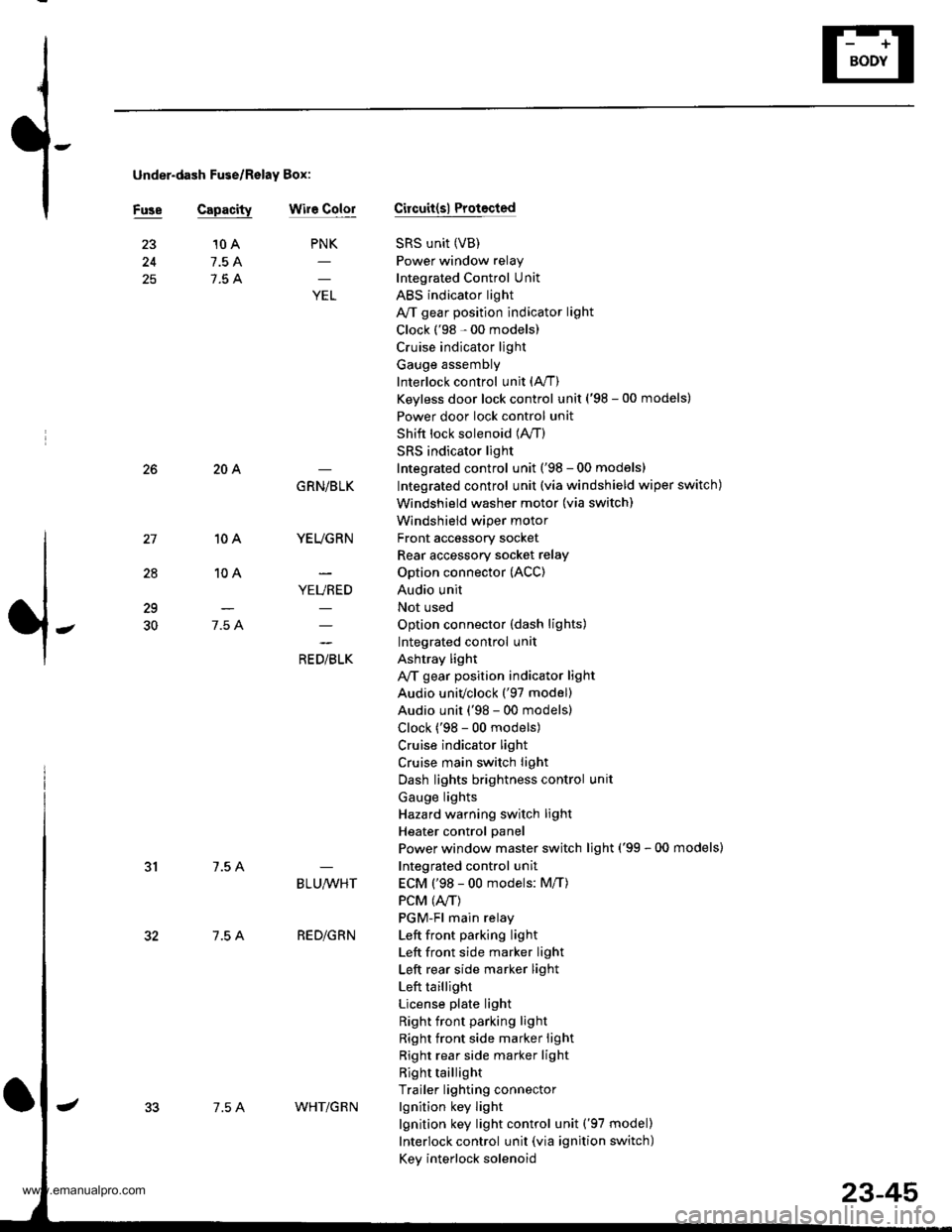
under-dash Fuse/Relay Box:
Fuse Capacitywir6 ColorCircuit(sl Protocted
SRS unit (VB)
Power window relay
Integrated Control Unit
ABS indicator light
A/T gear position indicator light
Clock ('98 - 00 models)
Cruise indicator light
Gauge assembly
Interlock control unit (A,/T)
Keyless door lock control unit ('98 - 00 models)
Power door lock control unit
Shift lock solenoid (lVT)
SRS indicator light
Integrated control unit ('98 - 00 models)
Integrated control unit (via windshield wiper switch)
Windshield washer motor (via switch)
Windshield wiper motor
Front accessory socket
Rear accessory socket relay
Option connector (ACC)
Audio unit
Not used
Option connector (dash lights)
Integrated control unit
Ashtray light
A,/T gear position indicator light
Audio univclock ('97 model)
Audio unit ('98 - 00 models)
Clock ('98 - 00 models)
Cruise indicator light
Cruise main switch light
Dash lights brightness control unit
Gauge lights
Hazard warning switch light
Heater control panel
Power window master switch light ('99 - 00 models)
Integrated control unit
ECM ('98 - 00 models: M/T)
PCM (4./T)
PGM-Fl main relay
Left front pa.king light
Left front side marker light
Left rear side marker light
Left taillight
License plate light
Right front parking light
Right front side marker light
Right rear side marker light
Right taillight
Trailer lighting connector
lgnition key light
lgnition key light control unit ('97 model)
Interlock control unit (via ignition switch)
Key interlock solenoid
25
PNK
;
10 A
7.5 A
7.5 A
28
10A
10A
7.5 A
204
7.5 A
7.5 A
GRN/BLK
YEUGRN
YEURED
a, olrL"
29
30
BLU,ryVHT
RED/GRN
7.5 AWHT/G R N
23-45
www.emanualpro.com