step HONDA CR-V 1997 RD1-RD3 / 1.G Workshop Manual
[x] Cancel search | Manufacturer: HONDA, Model Year: 1997, Model line: CR-V, Model: HONDA CR-V 1997 RD1-RD3 / 1.GPages: 1395, PDF Size: 35.62 MB
Page 55 of 1395

Starting System
Starter Test
NOTE: The air temperature must be between 59 and'100'F (15 and 38"C) before testing.
Recommended Procedure:
. Use a staner system tester.
. Connect and operate the equipment in accordance
with the manufacturer's instructions.
. Test and troubleshoot as described.
Alte.nate Procedure:
. Use the following equipment:- Ammeter, 0 - 400 A- Voltmeter, 0 - 20 V (accurate within 0.1 volt)
Tachometer,0 - 1,200 rpm
. Hook up a voltmeter and ammeter as shown.
NOTE: After this test, or any subsequent repair. reset
the ECM/PCM to clear any codes (see section 1 1).
Check the Starter Engagement:
'1. Remove the No. 44 (15 A) fuse from the under-hood
fuse/relay box.
2. Turn the ignition switch to START (lll) with the shift
lever in E or E position (A/T) or with the clutch
pedal depressed {M/T). The starter should crank the
eng ine.
. lf the starter does not crank the engine, go to
step 3.
. lf it cranks the engine erratically or too slowly, go
to "Check for Wear and Damage" on the next
page.
NEGATIVE TERMINAL
4.
5.
6.
7.
8.
Check the battery, battery positive cable, ground.
staner cut relay, and the wire connections for loose-
ness and corrosion. Test again.
lf the staner still does not crank the engine, go to
step 4.
Unplug the connector (BLK /VHT wire and solenoid
terminal) from the starter.
Connect a jumper wire from the baftery positive (+)
terminal to the solenoid terminal.
The starter should crank the engine.
. lf the starter still does not crank the engine,
remove it, and diagnose its internal problem.
. lf the starter cranks the engine, go to step 6.
Check the ignition switch (see section 23).
Check the starter cut relay {see section 23}.
Check the IVT gear position switch (A/T) or the clutch
interlock switch (M[).
Check for an open in the wire between the ignition
switch and starter.
(cont'd)
4-5
www.emanualpro.com
Page 69 of 1395
lgnition Control Module (lCMl Input Test
NOTE:
. See section 11 when the malfunction indicator lamp(MlL) comes on.
. Perform an input test for the ignition control module(lCM) after finishing the fundamental tests for the
ignition system and the fuel and emissions systems.
. '97 -'98 models: The tachometer should operate nor-
mally if the ICM is OK.
L Remove the distributor ignition (Dl) cap, the distrib-
utor ignition (Dl) rotor, and the leak cover.
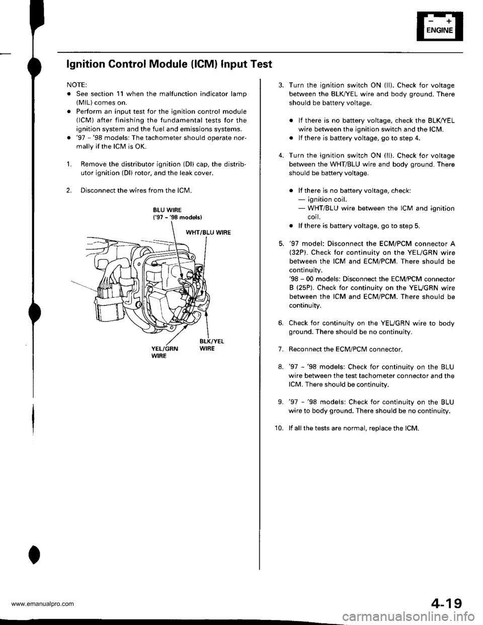
2. Disconnect the wires from the lCM.
8LU WIRE{'97 - '98 models}
4-19
7.
Turn the ignition switch ON {ll). Check for voltage
between the BLK,^/EL wire and body ground. There
should be battery voltage.
. lf there is no battery voltage, check the BLK/rEL
wire betlveen the ignition switch and the lclvl.
. lf there is baftery voltage, go to step 4.
Turn the ignition switch ON (ll). Check for voltage
between the WHT/BLU wire and body ground. There
should be battery voltage.
. lf there is no batteryvoltage, check:- ignition coil.- WHT/BLU wire between the ICM and ignition
corl.
. lf there is battery voltage, go to step 5,
'97 model: Disconnect the ECM/PCM connector A(32P). Check for continuity on the YEL/GRN wire
between the ICM and ECM/PCM. There should be
continuity.'98 - 00 models: Disconnect the ECM,PCM connector
B (25P). Check for continuity on the YEUGRN wire
between the ICM and ECM/PCM. There should be
continuity.
Check for continuity on the YEUGRN wire to body
ground. There should be no continuity.
Reconnect the ECM/PClvl connector.
'97 -'98 models: Check for continuity on the BLU
wire between the test tachometer connector and the
lCM. There should be continuity.
'97 -'98 models: Check for continuity on the BLU
wire to body ground. There should be no continuity.
lf all the tests are normal, replace the lCM.
9.
'10.
www.emanualpro.com
Page 83 of 1395
Rotor Slip Ring Test
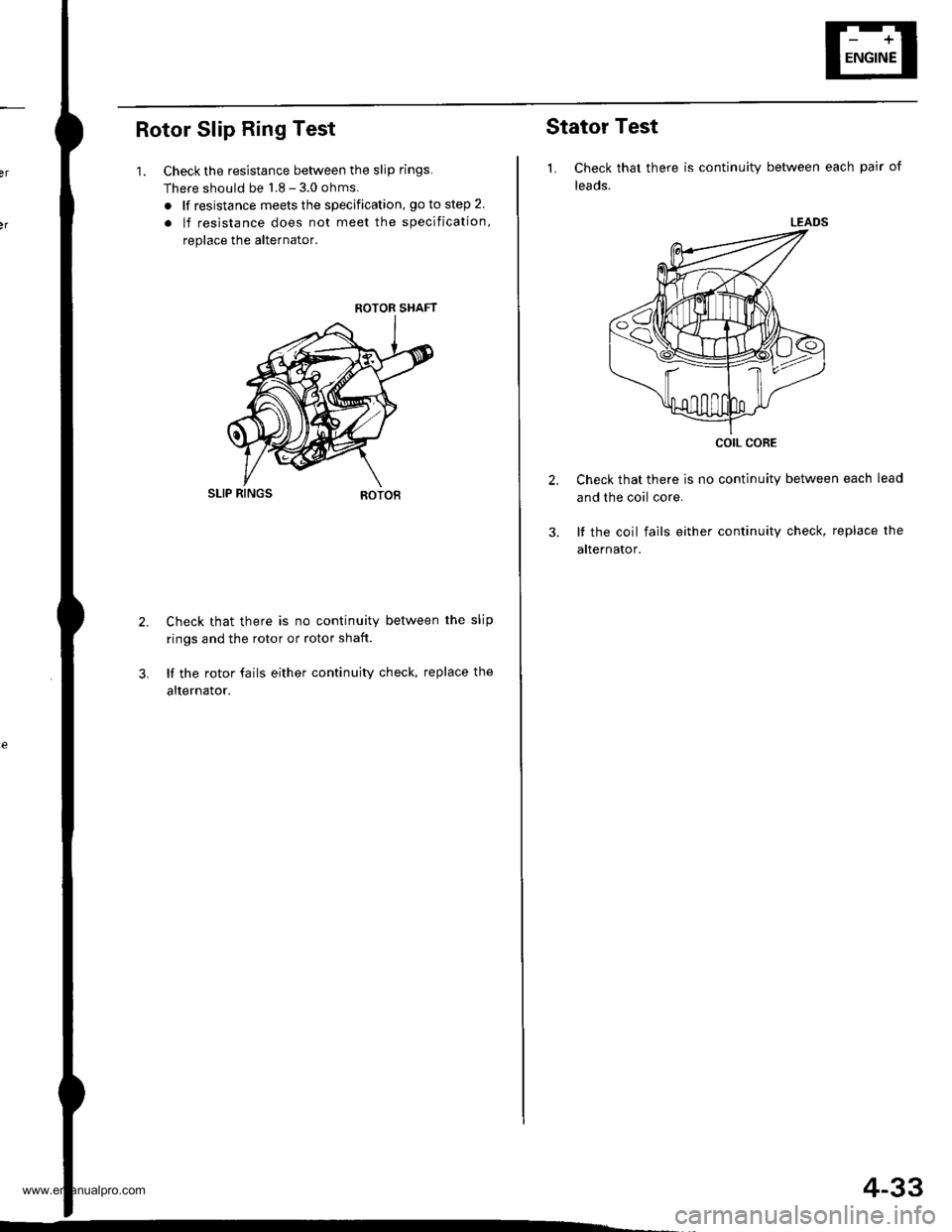
1. Check the resistance between the slip rings.
There should be 1.8 - 3.0 ohms.
. lf resistance meets the specification, go to step 2
. lf resistance does not meet the specification,
replace the alternator.
SLIP RINGS
Check that there is no continuity between the slip
rings and the rotor or rotor shaft.
lf the rotor fails either continuity check, replace the
alternator.
ROTOR SHAFT
4-33
Stator Test
1. Check that there is continuity between each pair of
leads.
Check that there is no continuity between each lead
and the coil core.
It the coil fails either continuity check, replace the
alternator.
LEADS
corL coRE
www.emanualpro.com
Page 90 of 1395
Cruise Control
1.
Main Switch Test/Replacement
Carefully pry the switch out of the instrument panel.
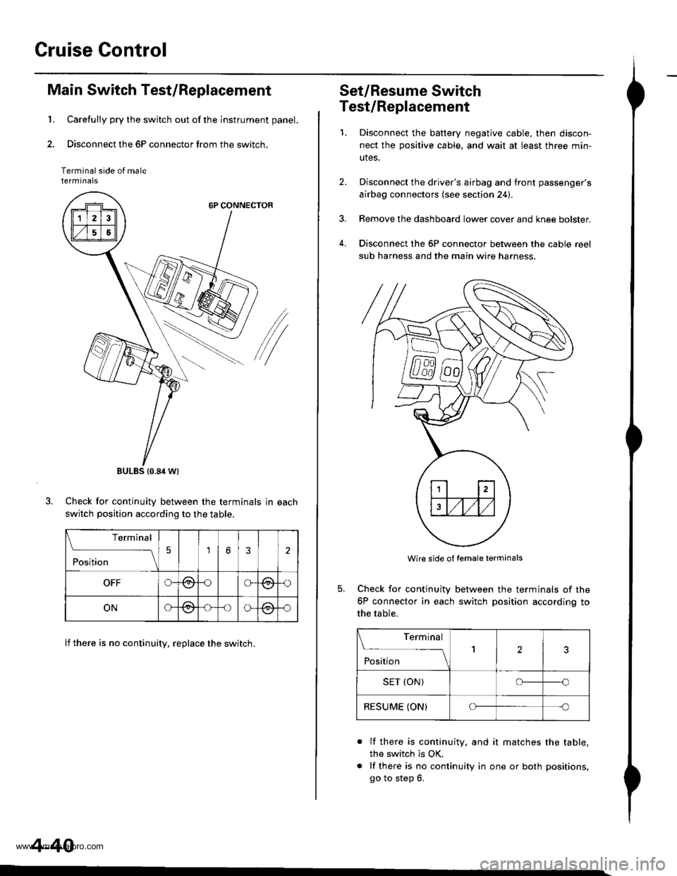
Disconnect the 6P connector from the switch,
Terminal side of malerermtnats
6P CONNECTOR
/
Check for continuitv between the terminals in each
switch position according to the table.
lf there is no continuity, replace the switch.
BULES {0.84 Wt
Terminal
;;;
-_\56
OFFG-@oG(9,{)
ONG@-oo-@-o
4-40
Set/Resume Switch
Test/Replacement
1.Disconnect the baftery negative cable, then discon-
nect the positive cable, and wait at least three min-
utes.
Disconnect the driver's airbag and front passenger's
airbag connectors (see section 24).
Remove the dashboard lower cover and knee bolster.
Disconnect the 6P connector between the cable reel
sub harness and the main wire harness.
4.
Wire side of temale terminals
Check for continuity
6P connector in each
the table.
between the terminals of the
switch position according to
Terminal
;;;
--_l2
SET (ON)o--o
RESUME (ON)Cf-c
a
lf there is continuity. and it matches the table,
the switch is OK.
lf there is no continuity in one or both positions,
go to step 6.
www.emanualpro.com
Page 92 of 1395
Cruise Gontrol
Actuator Test (cont'dl
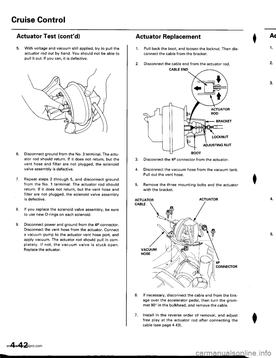
5. With voltage and vacuum still applied, try to pull the
actuator rod out by hand. You should not be able topull it out. lf you can. it is defectrve.
8.
9.
7.
Disconnect ground from the No. 3 terminal. The actu-
ator rod should return. lf it does not return, but the
vent hose and filter are not plugged, the solenoid
valve assembly is defective.
Repeat steps 2 through 5. and disconnect ground
from the No. l terminal. The actuator rod should
return. lf it does not return, but the vent hose and
filter are not plugged, the solenoid valve assembly
is defective.
lf you replace the solenoid valve assembly, be sure
to use new O-rings on each solenoid.
Disconnect power and ground from the 4P connector.
Disconnect the vent hose from the actuator. Connect
a vacuum pump to the actuator vent hose port, and
apply vacuum. The actuator rod should pull in com-pletely. lf not, the vacuum valve is stuck open.
Replace the actuator,
4-42
I
't.
Actuator Replacement
3.
4.
7.
Ar
Pull back the boot. and loosen the locknut. Then dis-
connect the cable from the bracket.
Disconnect the cable end from the actuator rod.
1.
4.
.J.
Disconnect the 4P connector from the actuator.
Disconnect the vacuum hose from the vacuum tank.
Pull out the vent hose.
Remove the three mounting bolts and the actuator
with the bracket.
ACTUATORACTUATOR
CABLE
lf necessary, disconnect the cable end from the link-
age over the accelerator pedal, then turn the grom-
met 90' in the bulkhead. and remove the cable.
Install in the reverse order of removal, and adjust
free play at the actuator rod after connecting the
cable (see page 4-43).
I
6.
I
www.emanualpro.com
Page 119 of 1395
Valve Seals
12.
Replacement (cylinder head removal not requiredl (cont'dl
Using an upward motion on the lever arm, compress
the valve spring and remove the keepers from the
valve stem. Slowly release pressure on the spring.
Repeat step 11 for the other valve in that cylinder.
Remove the valve seals (see page 6-24).
Installthe valve seals (see page 6-29).
lnstall the springs, the retainers and the keepers in
reverse order of removal.
'17. Repeat steps 9 to 16 for the other three cylinders.
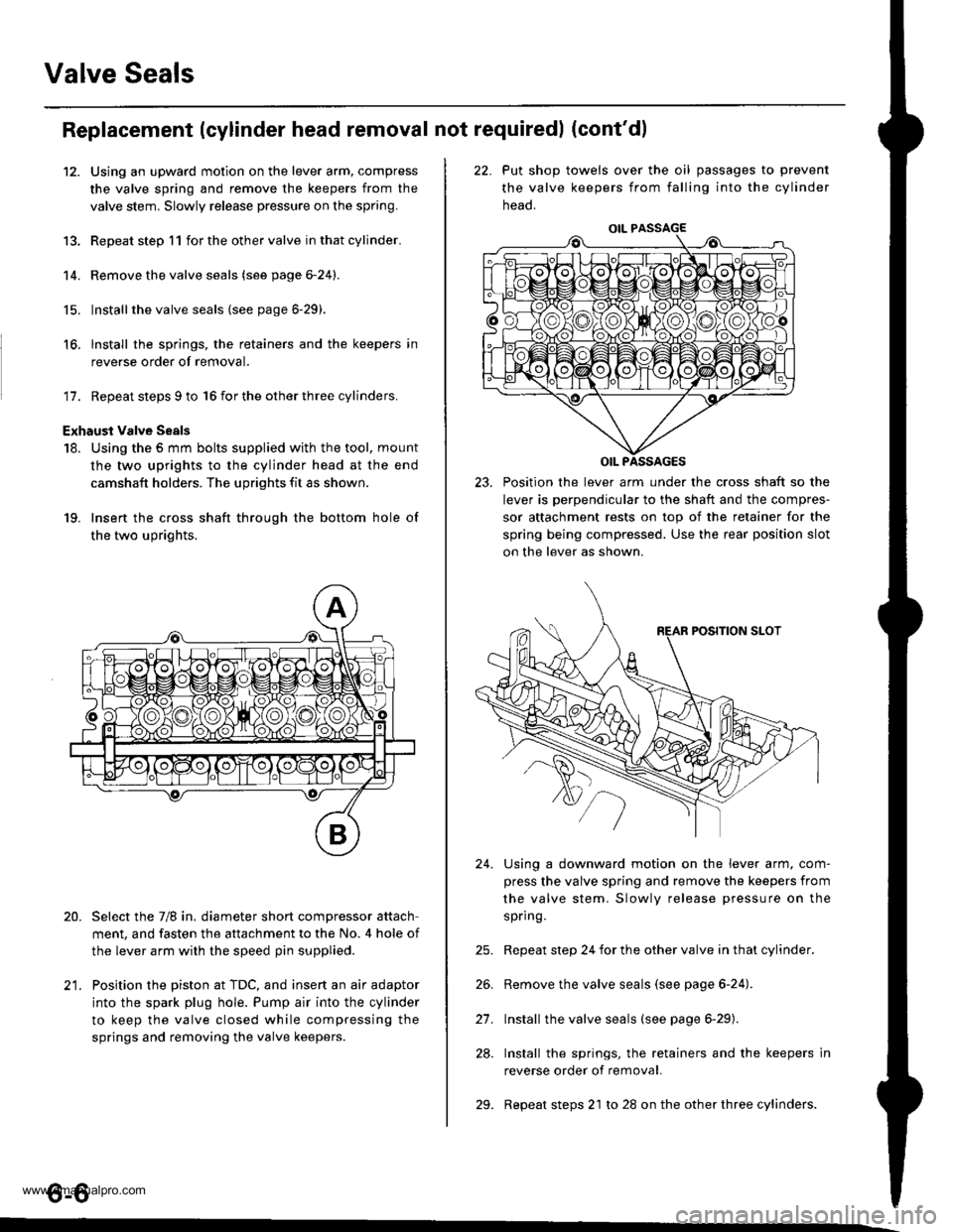
Exhaust valve Seals
18. Using the 5 mm bolts supplied with the tool, mount
the two uprights to the cylinder head at the end
camshaft holders. The uprights fit as shown.
19. Insert the cross shaft through the bottom hole of
the two uprights.
Select the 7/8 in. diameter short compressor attach
ment, and fasten the attachment to the No. 4 hole of
the lever arm with the speed pin supplied.
Position the piston at TDC, and insert an air adaptor
into the spark plug hole. Pump air into the cylinder
to keep the valve closed while compressing the
springs and removing the valve keepers.
13.
14.
15.
16.
20.
t1
22. Put shop towels over the oil passages to prevent
the valve keepers from falling into the cylinder
neao.
23. Position the lever arm under the cross shaft so the
lever is perpendicular to the shaft and the compres-
sor attachment rests on top of the retainer for the
spring being compressed. Use the rear position slot
on the lever as shown.
Using a downward motion on the lever arm, com-
press the valve spring and remove the keepers from
the valve stem. Slowly release pressure on the
spring.
Repeat step 24 for the other valve in that cylinder.
Remove the valve seals (see page 6-24).
Install the valve seals (see page 6-29).
Install the springs, the retainers and the keepers in
reverse order of removal.
Repeat steps 21 to 28 on the other three cylinders.
24.
21.
28.
29.
o-o
www.emanualpro.com
Page 143 of 1395
Cylinder Head
Installation
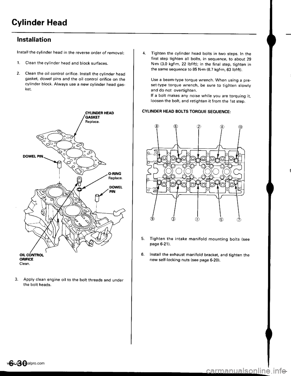
Installthe cylinder head in the reverse order of removal:
1. Clean the cylinder head and block surfaces.
2. Clean the oil control orifice. Install the cylinder headgasket, dowel pins and the oil control orifice on thecylinder block. Always use a new cylinder head gas-ket.
CYLII{DER HEADGASKETR€place.
DOWEL PIN
O.RINGRoplace.
DOWELPIN
OIL CONTBOLORIFICEClean.
Apply clean engine oil to the bolt threads and underthe bolt heads.
4. Tighten the cylinder head bolts in two steps. In thefirst step tighten all bolts, in sequence, to about 29
N.m {3.0 kgf.m,22 lbf.ft); in the finat step, tighten inthe same sequence to 85 N.m (8.7 kgf.m,63 lbf.ft).
Use a beam-type torque wrench. When using a pre-
set-type torque wrench, be sure to tighten slowly
and do not overtighten.
lf a bolt makes any noise while you are torquing it,loosen the bolt, and retighten it from the 1st step.
CYLINDER HEAD BOLTS TOROUE SEOUENCE:
Tighten the intake manifold mounting bolts (see
page 6-21).
Install the exhaust manifold bracket. and tighten thenew self-locking nuts (see page 6-20).
6-30
www.emanualpro.com
Page 144 of 1395
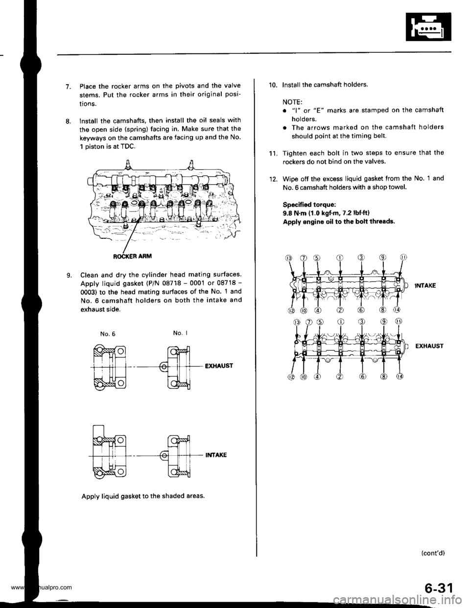
7.Place the rocker arms on the pivots and the valve
stems. Put the rocker arms in their original posi-
lrons.
lnstall the camshafts, then install the oil seals with
the open side (spring) facing in. Make sure that the
keyways on the camshafts are facing up and the No.
1 piston is at TDC.
Clean and dry the cylinder head mating surfaces.
Apply liquid gasket (P/N 08718 - 0001 or 08718 -
0OO3) to the head mating surfaces of the No. 1 and
No. 6 camshaft holders on both the intake and
exhaust side.
L
No. I
EXHAUST
II{TAKE
Apply liquid gasket to th€ shaded areas.
't't,
'10. lnstall the camshaft holders.
NOTE:
o "1" or "E' marks are stamped on the camshaft
holders.
. The arrows marked on the camshaft holders
should point at the timing belt.
Tighten each bolt in two steps to ensure that the
rockers do not bind on the valves.
Wipe off the excess liquid gasket from the No. 1 and
No. 6 camshaft holders with a shop towel,
Specified torque:
9.8 N.m (1.0 kgf.m, 7.2 lbf.ft)
Apply engine oil to the bolt ihreads.
I?,ITAKE
EXHAUST
(cont'd)
6-31
www.emanualpro.com
Page 146 of 1395
21.
22.
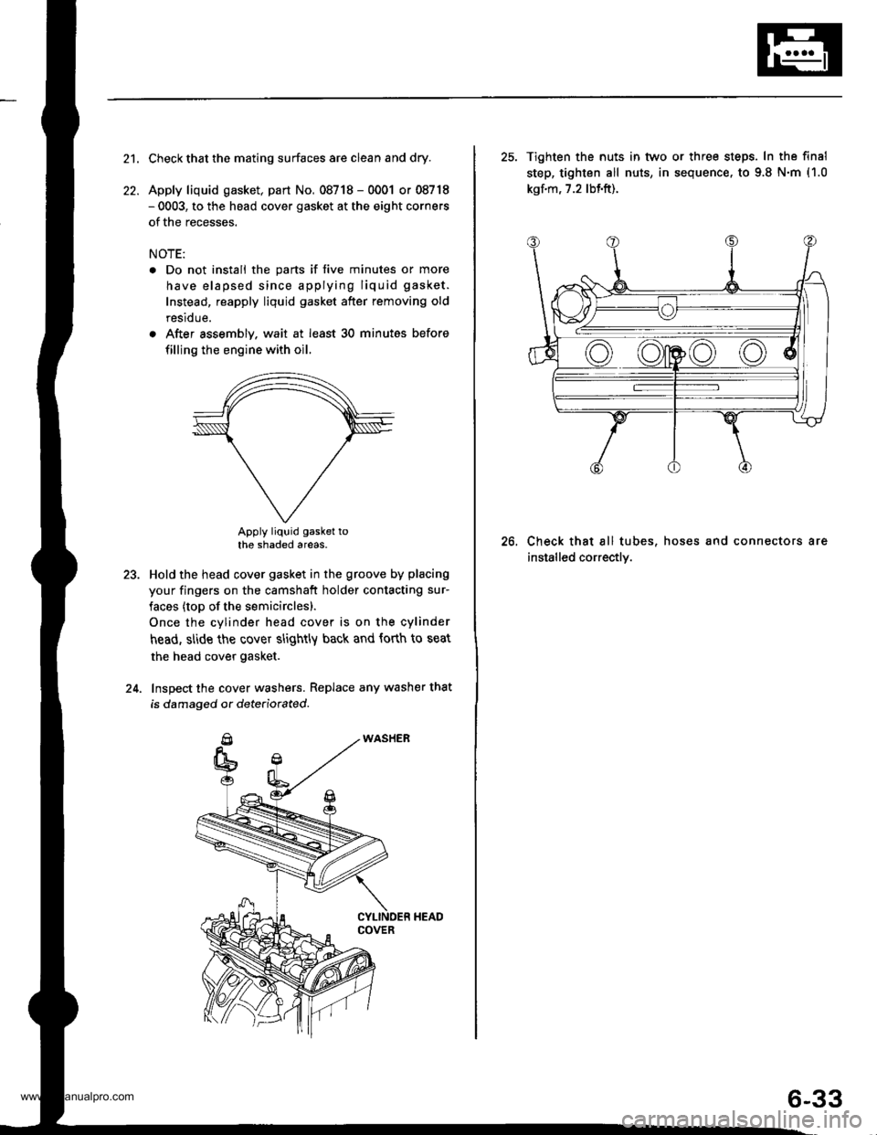
Check that the mating surfaces are clean and dry.
Apply liquid gasket, part No. 08718 - 0001 or 08718- 0003, to the head cover gasket at the eight corners
of the recesses.
NOTE:
. Do not install the parts if five minutes or more
have elapsed since applying liquid gasket.
Instead, reapply liquid gasket after removing old
residue.
. After assembly. wait at least 30 minutes before
filling the engine with oil.
Apply liquid gasket tothe shaded areas.
Hold the head cover gasket in the groove by placing
your fingers on the camshaft holder contacting sur-
faces (top of the semicirclesl.
Once the cylinder head cover is on the cylinder
head, slide the cover slightly back and forth to seat
the head cover gasket.
Inspect the cover washers. Replace any washer that
is damaged or dete(iorated.
23.
24.
25. Tighten the nuts in tvvo or three steps. In the final
step, tighten all nuts, in sequence. to 9.8 N.m (1.0
kgf.m, 7.2 lbf.ft).
Check that all tubes, hoses and connectors are
installed correctly.
26.
6-33
www.emanualpro.com
Page 153 of 1395
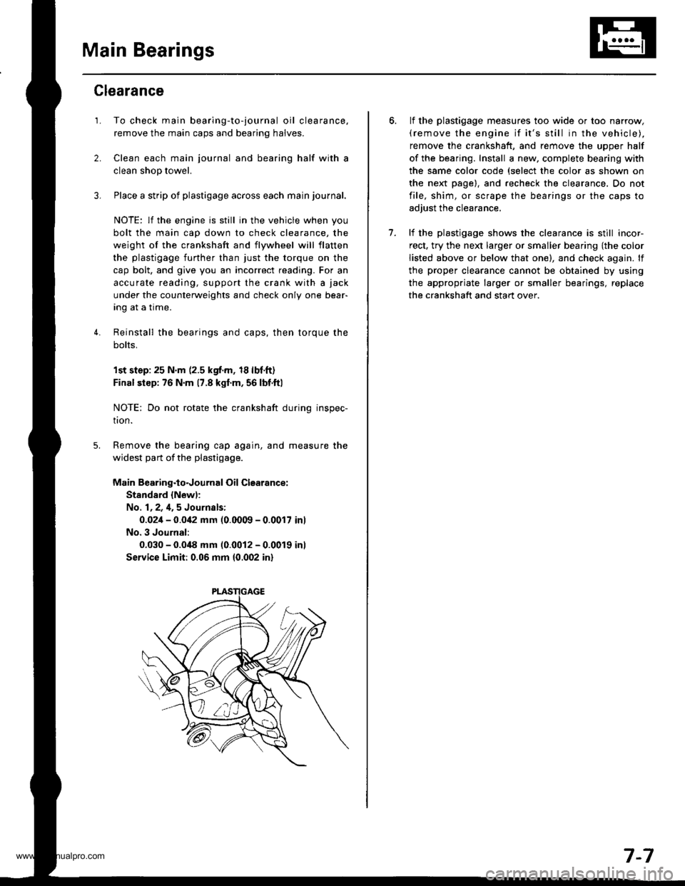
Main Bearings
2.
3.
1.
4.
Clearance
To check main bearing-to-journal oil clearance,
remove the main caps and bearing halves.
Clean each main journal and bearing half with a
clean shop towel.
Place a strip of plastigage across each main journal.
NOTE: lf the engine is still in the vehicle when you
bolt the main cap down to check clearance, the
weight of the crankshaft and flywheel will flatten
the plastigage further than just the torque on the
cap bolt, and give you an incorrect reading. For an
accurale reading, support the crank with a jack
under the counterweights and check only one bear-
Ing aI a Irme.
Reinstall the bearings and caps, then torque the
bolts,
1st step:25 N'm (2.5 kgf.m, 18lbf.ft)
Final siep: 76 N'm 17.8 kgl.m, 56 lbf.ftl
NOTE: Do not rotate the crankshaft during inspec-
tron.
Remove the bearing cap again, and measure the
widest part of the plastigage.
Main Bearing.to.Journal Oil Clearance:
Stand8.d {New):
No. 1,2,4,5 Journsls:
0.02i1- 0.0i12 mm (0.0009 - 0.0017 inl
No. 3 Journal:
0.030 - 0.0i18 mm (0.0012 - 0.0019 inl
Service Limit: 0.06 mm 10.002 in)
lf the plastigage measures too wide or too narrow,(remove the engine if it's still in the vehicle),
remove the crankshaft, and remove the upper half
of the bearing. Install a new, complete bearing with
the same color code (select the color as shown on
the next page). and recheck the clearance, Do not
file, shim, or scrape the bearings or the caps to
adjust the clearance.
lf the plastjgage shows the clearance is still incor-
rect, try the ne)d larger or smaller bearing {the color
listed above or below that one), and check again. lf
the proper clearance cannot be obtained by using
the appropriate larger or smaller bearings, replace
the crankshaft and start over.
7.
7-7
www.emanualpro.com