Oil HONDA CR-V 1998 RD1-RD3 / 1.G Workshop Manual
[x] Cancel search | Manufacturer: HONDA, Model Year: 1998, Model line: CR-V, Model: HONDA CR-V 1998 RD1-RD3 / 1.GPages: 1395, PDF Size: 35.62 MB
Page 518 of 1395
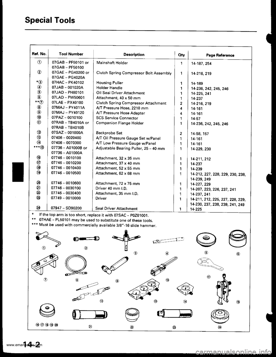
Ref. No.
^tl)
@
*rar
@
@
,-o
@
o
@
@
@
@
@.--@
@
@
@
@
@
@
@
@
@
Tool NumberDescriptionOty I Pago Referonc€
Mainshaft Holder
Clutch Spring Compressor Bolt Assembly
Housing Puller
Holder Handle
Oil Seal Driver Aftachment
Attachment, 40 x 50 mm
Clutch Spring Compressor Attachment
Ay'T Pressure Hose, 2210 mm
IVT Pressure Hose Adapter
SCS Service Connector
Companion Flange Holder
Backprobe Set
lVT Oil Pressure Gauge Set w/Panel
A,/T Low Pressure Gauge w/Panel
Adjustable Bearing Puller, 25 - 40 mm
Anachment, 32 x 35 mm
Attachment, 37 x 40 mm
Attachment. 52 x 55 mm
Attachment. 62 x 68 mm
Attachment, 72 x 75 mm
Driver 40 mm l.D.
Attachment, 35 mm LD.
Driver
07GAB - PF50101 or
07GAB - PF50100
07GAE - PG40200 or
OTGAE _ PG4O2OA
07HAC - PK40102
07JAB - 001020A
07JAD - PH80101
07LAD - PW50601
07LAE - PX40100
OTMAJ - PY4O114
07MAJ - PY40120
07 PAZ - 0010100
07RAB - TB4010A or
07RAB.TB40lOB
07sAz - 001000A
07406 - 0020400
07406 - 0070300
07736 - 4010008 or
07736 - A010004
07746 - 0010100
07746 - 0010200
07746 - 0010400
07746 - 0010500
07746 - 0010600
07746 - 0030100
07746 - 0030400
07749 - 0010000
07947 - SD90200Seal Driver Aftachment
1
1
1
1,l
1
I
2
1'l
1
I
1
1
1
1
1
1
I
1
14-181 , 254
14-216,219
14-189't4-236,242,245,246
't 4-225, 241
14-237
14-216,2't9
14-161
14- 161
14-57
14-236,242,245,246
14-58, 157
14-161
14-161'14-229,230
14-211, 2't2
14-231
14-239
14-212, 227 , 228,229, 230, 238,
14-239, 249
14-221 ,229't 4-207 , 223,226, 237 , 241
14-237,241
1 +21 1, 2't2, 225, 227, 228, 229,
14-230, 237 , 238, 239, 24't, 249't4-225
lf the top arm is too short, replace it with 07SAC - pOZ01OO1.
07HAE - PL50101 may be used to substitute one of these tools.Must be used with commercially available 3/8"-16 slide hammer.
E----G
@@@@@
@
tvj
'
@@@)
14-2
www.emanualpro.com
Page 652 of 1395
Shift Control Solenoid Valve A/B Assembly
Test
'1. Disconnect the 2P connector from
solenoid valve Ay'B assembly.
the shift control
Terminalsade ofmale terminals
Measure the resistance between the No. 1 terminal(solenoid valve A) of the shift control solenoid valve
connector and body ground, and between the No. 2terminal (solenoid valve B) and body ground.
STANDARD: 12 - 25 O
Replace the shift control solenoid valve A,/B assem-bly if the resistance is out of specification.
lf the resistance is within the standard. connect theNo, I terminal of the shift control solenoid valveconnector to the battery positive terminal. A clickingsound should be heard. Connect the No. 2 terminalto the battery positive te.minal. A clicking soundshould be heard. Replace the shift control solenoidvalve A/B assembly if no clicking sound is heardwhen either terminal is connected to the battervpositive terminal.
14-136
Replacement
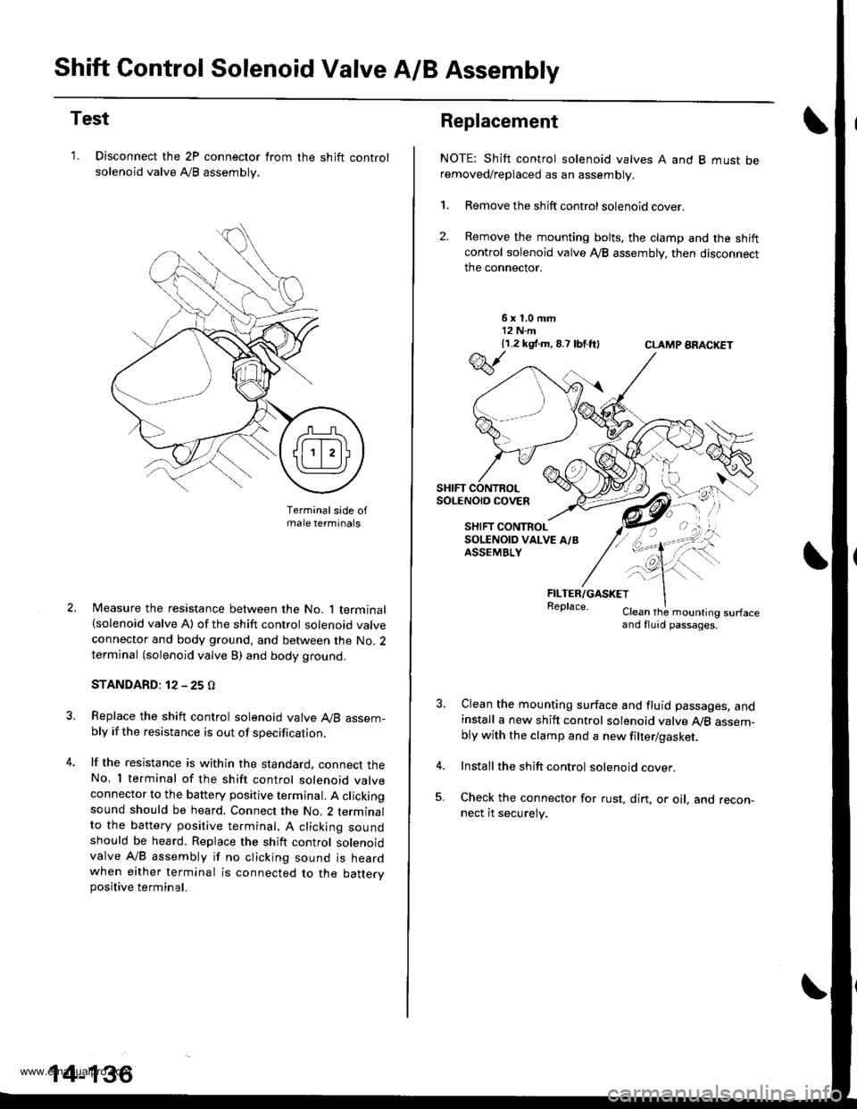
NOTE: Shift control solenoid valves A and B must beremoved/replaced as an assembly.
1. Remove the shift control solenoid cover.
2. Remove the mounting bolts, the clamp and the shiftcontrol solenoid valve Ay'B assembly, then disconnect
the connector.
6x1.0mm12 N.m{1.2 k9 .m,8.7 lbtft}CLAMP ARACKET
FILTER/GASKETReplace.Clean the mounling surfaceand fluid passages.
Clean the mounting surface and fluid passages. andinstall a new shift control solenoid valve Ay'B assem-bly with the clamp and a new filter/gasket.
Install the shift control solenoid cover.
Check the connector for rust, dirt. or oil, and recon-nect it securely.
w
SHIFT CONTROLSoLENO|O COVEn
SHIFT CONTROLSOLENOID VALVE A/BASSEMBLY
\--
qK
-!t'">,,
www.emanualpro.com
Page 654 of 1395
Mai nshaft /Cou ntershaft
Linear Solenoid AssemblySpeed Sensors
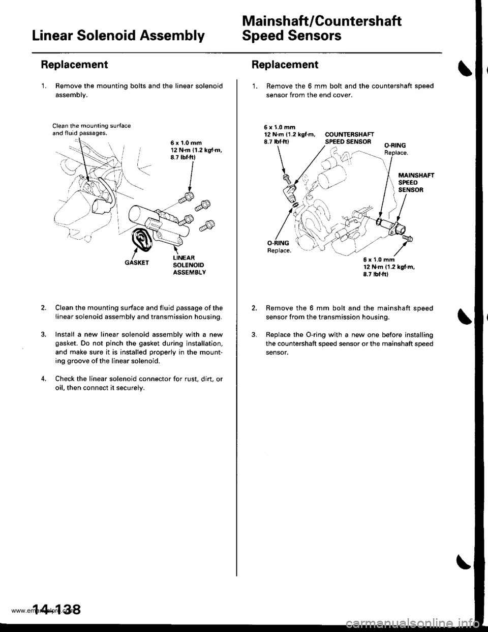
Replacement
'1. Remove the mounting bolts and the linear solenoid
assemblY.
Clean the mounting surfaceand fluid passages.
6x1.0mm12 N.m (1.2 kg{.m.8.7 tbtftl
@
@
GASKET
Clean the mounting surface and fluid passage of the
linear solenoid assembly and transmission housing.
Install a new linear solenoid assemblv with a new
gasket. Do not pinch the gasket during installation,
and make sure it is installed properly in the mount-
ing groove of the linear solenoid.
Check the linear solenoid connector for rust. dirt, or
oil, then connect it securelv.
14-138
Replacement
1. Remove the 6 mm bolt and the countershaft sDeed
sensor from the end cover.
\
5x1.0mm12 N.m 11.2 kgf.m, COUNTERSHAFT8.7 rbf.frl SPEED SENSOR
O.RINGReplace.
12 N'm 11.2 kgl.m,8.7 tbf.ftl
Remove the 6 mm bolt and the mainshaft speed
sensor from the transmission housing.
Replace the O-ring with a new one before installing
the countershaft speed sensor or the mainshaft speed
sensor,
6x1.0mm
www.emanualpro.com
Page 671 of 1395
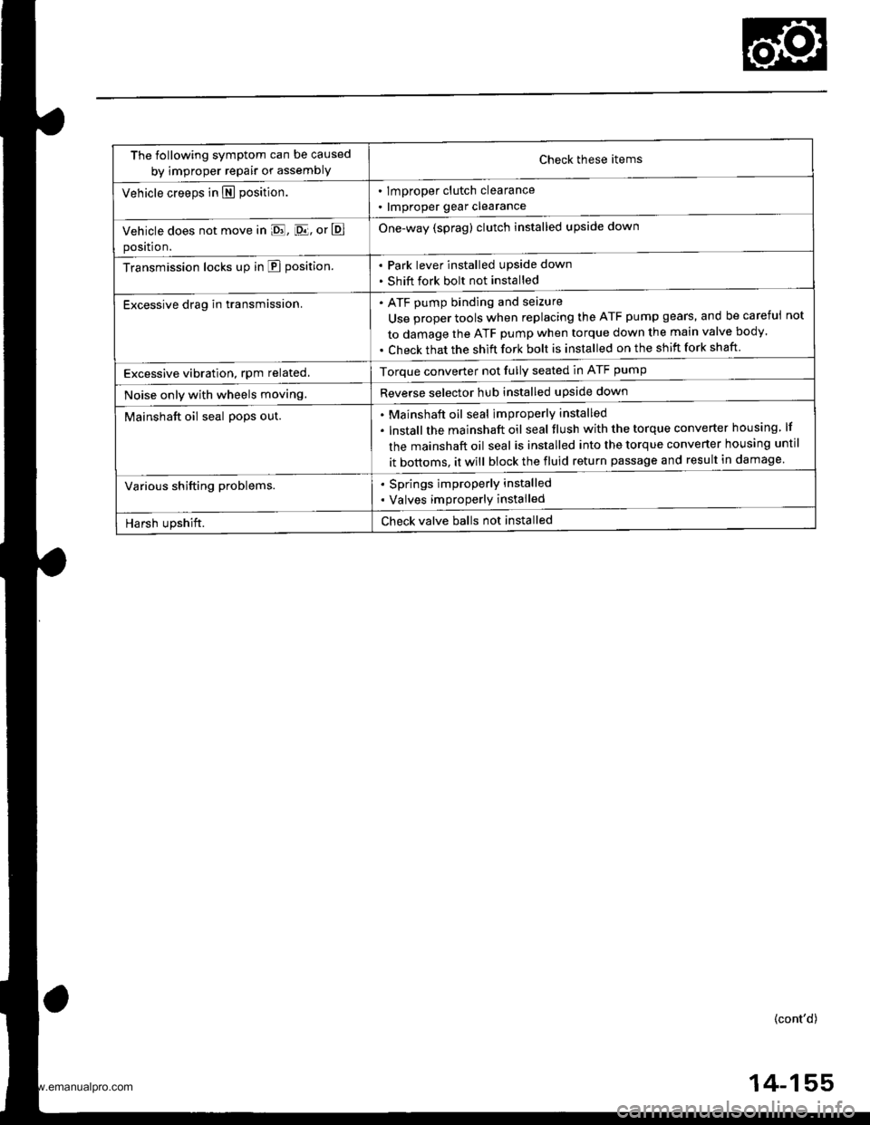
The following symptom can be caused
by improper repair or assemblYCheck these items
. lmproper clutch clearance
. lmproper gear clearance
One-way (sprag) clutch installed upside down
Park lever installed upside down
Shift fork bolt not installed
Vehicle creeps in N position.
Vehicle does not move in E, [D.lj, or E
position.
Transmission locks up in E position.
Excessive drag in transmission.ATF pump binding and seizure
Use proper tools when replacing the ATF pump gears, and be careful
to damage the ATF pump when torque down the main valve body.
Check that the shift fork bolt is installed on the shift fork shaft
not
Excessive vibration, rpm related.Torque converter not fully seated in ATF pump
Reverse selector hub installed upside downNoise only with wheels moving.
Mainshaft oil seal po9s out.Mainshaft oil seal improperly installed
lnstallthe mainshaft oil seal tlush with the torque converter housing lf
the mainshaft oil seal is installed into the torque converter housing until
it bottoms. it will block the fluid return passage and result in damage
Various shifting problems.. Springs improperly installed
. Valves improperly installed
Harsh upshift.Check valve balls not installed
(cont'd)
4-155
www.emanualpro.com
Page 677 of 1395

Pressure Testing
Changing
NOTE: Keep all foreign particles out of the transmis-
sion.
1. Bring the transmission up to operating temperature
(the radiator fan comes on) by driving the vehicle.
Park the vehicle on level ground. turn the engane
off. then remove the drain Plug.
NOTE: lf a cooler flusher is to be used, see page
14-264 and 14-265.
TRANSMISSIONEND COVER
DRAIN18 x 1.5 mmSEALING WASHEBReplace.49 N.m {5.0 kgt.m, 36 lbf.tl)
Reinstall the drain plug with a new sealing washer,
then refill the transmission with the recommended
fluid to the uDper mark on the dipstick. Always use
Genuine Honda Premium Formula Automatic
Transmission Fluid (ATF) Using a non-Honda ATF
can affect shift quality.
Automatic Transmission Fluid Capacity:
4WD;
2.9 { (3.1 US qt. 2.6 lmp qt) 8t change
5.8 ? {7.2 US $, 6.0 lmp qt} at ovethaul
2WD:
2.7 | l2.S US qt,2.1lmp qtl ai change
5.9 ? {6.2 US $, 5.2 lmp qtl at ovolhaul
2.
a
a
1.
Wlrile testing, be careful of the rotaling wheols.
Mako sure lifts, iacks, and safety stands ar€ placed
properly (see scction 11.
Before testing, be sure the transmission fluid is
filled to the proPer level.
4WD:
Raise the vehicle (see section 11.
2WD:
Raise the front of the vehicle, and make sure it is
securely supported. Set the parking brake, and block
both rear wheels securely.
Allow all four wheels {4WD) or front wheels (2wD}
to rotate freely.
Warm up the engine (the radiator fan comes on),
then stop it and connect the tachometer.
Connect the oil pressure gauges to each inspection
hole securely, and do not allow dust or other foreign
particles to enter the inspection holes.
TOROUE: 18 N'm ll.8 kgf'm, 13 lbf'ft)
5.
A/T PRESSURE HOS€,2210 mm07MAJ - PYiOllA
{4 Requircd}
,4'/"' ,a
W'
A/T PRESSURE HOSEADAPTER07MAJ - PYt0120(il Rcquiledl
6. Measure the following Pressure:. Line Pressure ..........,14-162
. 1st. 1st-hold Clutch Pressure .............'. 14-162
. 2nd,3rd and 4th Clutch Pressure .......... 14-163
7. Install new sealing washers and the sealing bolts in
the inspection holes, and tighten to the specified
toroue.
(cont'd)
A/T OIL PRESSUREGAUGE SET W/PANEL07{06 - 0020400
/4\\-J-- (
+..\.-.\-'-\
A/T LOW PBESSUREGAUGE w/PANEL07406 - 0070300
TOROUE: 18 N'm 11.8 kgf'm, 13 lbf'ft)
14-161
www.emanualpro.com
Page 680 of 1395
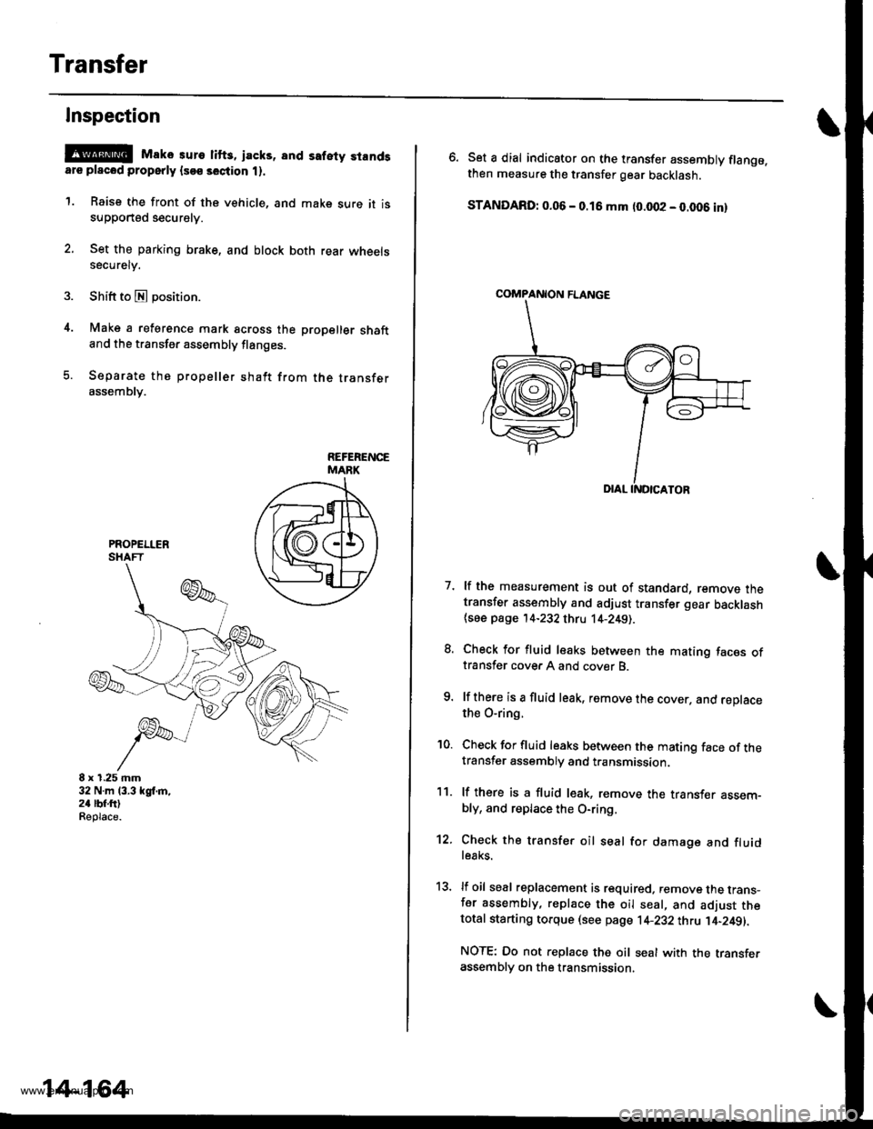
Transfer
4.
Inspection
@E Mako suro lifts, jacks, and safety standsare placod properly lsoe section t).
1. Raise the front of the vehicle, and make sure it issupported securely.
2. Set the parking brake, and block both rear wheelssecurely.
Shift to E position.
Make a reference mark across the propeller shaftand the transfer assembly flanges.
Separate the propeller shaft from the transferassembly.
8 x 1.25 mm32 N.m 13.3 kgl,m,24 lbf.ftlReplace.
14-164
\
6. Set a dial indicator on the transfer assembly flange.then measure the transfer gear backlash.
STANDARD: 0.06 - 0.16 mm (0.002 - 0.006 inl
7. lf the measurement is out of standard, remove thetransfer assembly and adjust transfer gear backlash{see page '14-232 thru 14-2491.
8. Check for fluid leaks between the mating faces oftransfer cover A and cover B.
9. lf there is a fluid leak, remove the cover, and reDlacethe O-ring.
'10. Check for fluid leaks between the mating face of thetransfer assembly and transmission.
11. lf there is a fluid l€ak, remove the transf€r assem-bly, and replace the O-ring,
12. Check the transfer oil seal for damage and fluidle8ks.
13, lf oil seal replacement is required. remove the trans-fer assembly, replace the oil seal, and adjust thetotal starting torque (see page 1+232 thtu ]'4-249||.
NOTE: Do not replace the oil seal with the transferassembly on the transmission.
COMPANION FLANGE
www.emanualpro.com
Page 687 of 1395
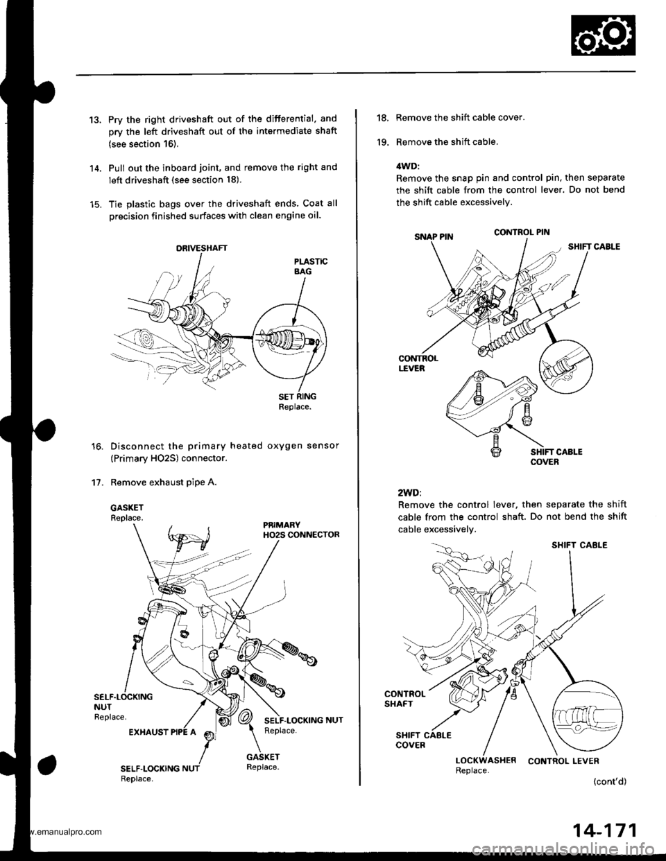
13.Pry the right driveshaft out of the differential. and
orv the left driveshaft out of the intermediate shaft
{see section 16).
Pull out the inboard joint, and remove the right and
left driveshaft (see section 18).
Tie plastic bags over the driveshaft ends. Coat all
Drecision finished surfaces with clean engine oil.
Disconnect the primary heated oxygen sensor
(Primary HO2S) connector.
Remove exhaust pipe A.
GASKETReplace.
14.
16.
't7 .
ORIVESHAFT
Replace.
EXHAUST
14-171
18.
19.
Remove the shift cable cover.
Remove the shift cable.
ilWD:
Remove the snap pin and control pin, then separate
the shift cable from the control lever. Do not bend
the shift cable excessively.
2WD:
Remove the control lever, then separate the shift
cable from the control shaft. Do not bend the shift
cable excessivelv.
Replace.
SHIFT CAELE
www.emanualpro.com
Page 688 of 1395
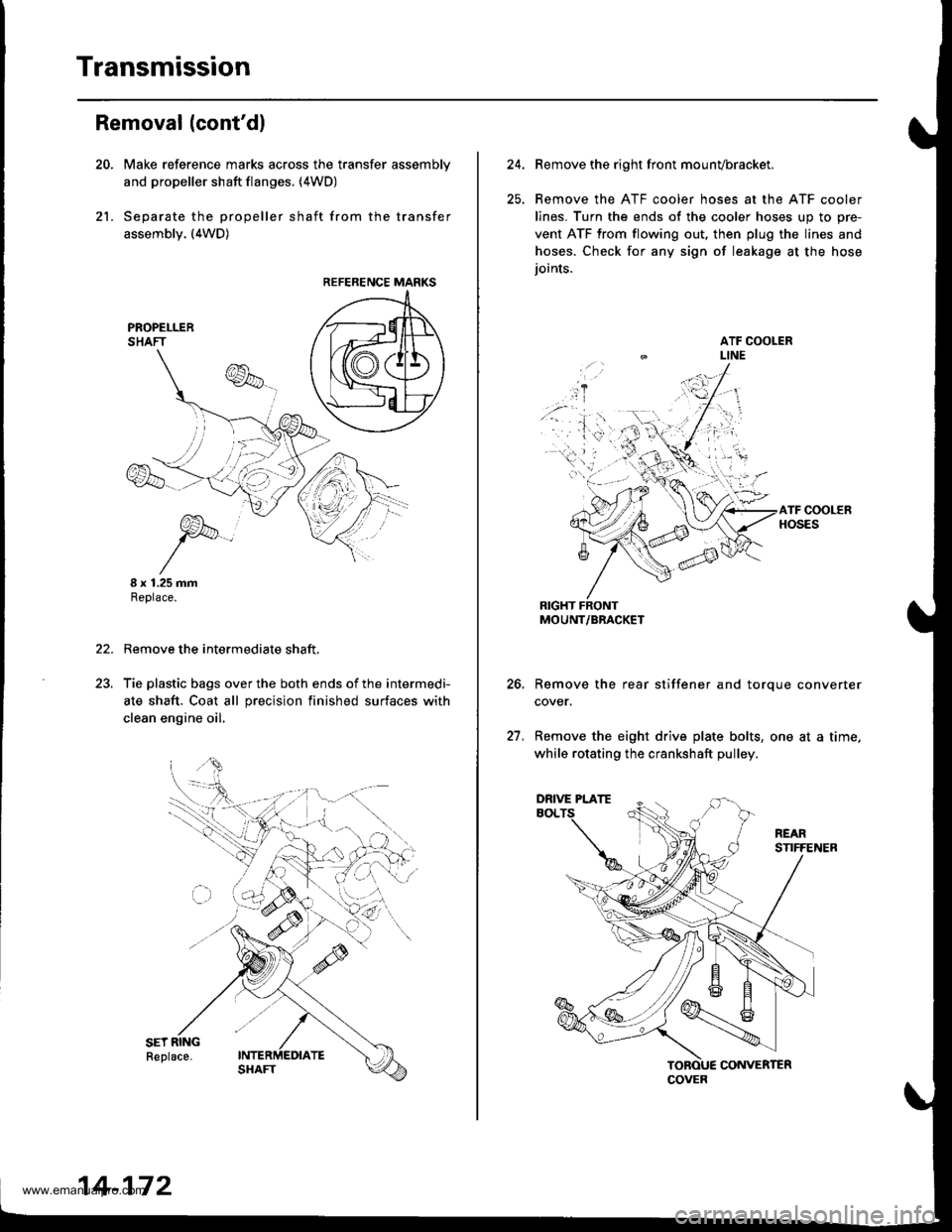
Transmission
21.
Removal (cont'dl
Make reference marks across the transfer assemblv
and propeller shaft flanges. (4WD)
Separate the propeller shaft from the transfer
assembly. (4WD)
I x 1.25 mmReplace.
Remove the intermediate shaft,
Tie plastic bags over the both ends of the intermedi-
ate shaft. Coat all precision finished surfaces with
clean engine oil.
22.
REFERENCE MARKS
14-172
24.Remove the right front mounvbracket.
Remove the ATF cooler hoses at the ATF cooler
lines. Turn the ends of the cooler hoses uo to ore-
vent ATF from flowing out, then plug the lines and
hoses. Check for any sign of leakage at the hose
ioints.
RIGHT FRONTMOUNT/BRACKET
Remove the rear stiffener and torque converter
cover.
Remove the eight drive plate bolts, one at a time.
while rotating the crankshaft pulley.
27.
COVER
DRIVE PLATE
www.emanualpro.com
Page 693 of 1395
![HONDA CR-V 1998 RD1-RD3 / 1.G Workshop Manual
r] REVERSE IDLER GEAR SHAFT/HOLDERA N€EDLE BEARING
..] TRANSMISSION HOUSING
al TRANSMISSION HOUSING OIL SEAL Replace.g SET BING.80 mm Selecrive part
O REVERSE GEAR COLLABE couNTERSHAFT REVERSE GEA HONDA CR-V 1998 RD1-RD3 / 1.G Workshop Manual
r] REVERSE IDLER GEAR SHAFT/HOLDERA N€EDLE BEARING
..] TRANSMISSION HOUSING
al TRANSMISSION HOUSING OIL SEAL Replace.g SET BING.80 mm Selecrive part
O REVERSE GEAR COLLABE couNTERSHAFT REVERSE GEA](/img/13/5778/w960_5778-692.png)
r] REVERSE IDLER GEAR SHAFT/HOLDER'A N€EDLE BEARING
..] TRANSMISSION HOUSING
al TRANSMISSION HOUSING OIL SEAL Replace.g SET BING.80 mm Selecrive part
O REVERSE GEAR COLLABE couNTERSHAFT REVERSE GEAB
.9,] NEEDLE BEARINGi9 LOCK WASHER Replace..1!i REVERSE SHIFT FORKO REVERSE SELECToRiJ. REVERSE SELECTOR HUBii' COUNTERSHAFT 4TH GEAR.14 NEEDLE BEARINGiD D|STANCE coLLAR,28 mm Selective part(i3 COUNTERSHAFT 2NO GEABi7-] THRUST NEEDLE BEARING(10 COUNTERSHAFT 3RD GEAR(9 NEEDLE BEARINGE9 COUNTERSHAFI3RD GEAB COLLAR.li THRUST NEEDLE BEARING.?) SPLINEO WASHER,,O 3RD CLUTCH ASSEMBLY
€1 O-RING Beplace.i23 COUNTERSHAFT
4i SHIFT CONTROL SOLENOID COVER
?Z] HARNESS CLAMP BRACKET
?9] SHIFT CONTROL SOLENOID VALVE A/B ASSEMBLY
8 HARNESS CLAMP BRACKET
GI SHIFT CONTROL SOLENOID VALVE FILTER/GASKET
(4 MAINSHAFT 2ND GEARi49 NEEDLE BEARING
@ THRUST NEEDLE BEARING(49 MAINSHAFT
@r SEAL|NG R|NG,35 mm
O SEALING RING,29 mm
@ NEEDLE BEARING
.49 SET RING
€) lST.HOLD CLUTCH ASSEMBLY
O o-RING Replace.6E THRUST WASHER
€9 THRUST NEEDLE BEARING
6' NEEDLE EEARING
€ir SUB-SHAFT 4TH GEAR
6 THRUST NEEDLE BEARING
@ SUB.SHAFT 4TH GEAR COLLAR@ sUB-sHAFf
6I NEEDI-E B€ARING STOP
@ NEEDLE BEARING(6t ATF GUIDE CAP Replace.(64 TRANSMISSION HANGEB
@ BREATHER CAP
i@ MAINSHAFT SPEED SENSOR
6i O-RING Replace.
6D REVERSE IDLER GEAR
@r DOWEL PlN, 14 x 25 mm.6d SNAP RINGS
QlI SUB.SHAFT TRANSMISSION HOUSING BEARING
E) MAINSHAFT TRANSMISSION HOUSING BEABING.2, COUNTERSHAFI TRANSMISSION HOUSINGBEARING
@[E
t,n9t0@)@),lD
04
@
@@:���������������.ro)
ai
Replace-SNAP RINGTHRUST WASHEBTHRUST NEEDLE BEARINGMAINSHAFT 4TH GEARNEEDLE BEARINGSTHRUST NEEDLE BEARINGMAINSHAFT 4TH GEAB COLLAR2NO/4TH CLUTCH ASSEMBLYO-RING Replace.THRUST WASHER,36.5 x 55 mm Selective partTHRUST NEEOLE BEARING
DOWEL PlN, 14 x 25 mmCONNECTOR BRACKETATF MAGNETDOWEL PlN, 14 x 20 mmTRANSMISSION HOUSING GASKET Replace.DIFFERENTIAL ASSEMBLYDOWEL PlN, 10 x 12 mmO-RING Replace.TRANSFER ASSEMBLYTOROUE CONVERTER HOUSING OIL SEAL Replace.TOROUE CONVERTER HOUSING
TOROUE SPECIFICATIONS
Bolt/Nut No.Torque ValueSizeRgmarks
6A
6B
10A
12 N.m (1.2 kgf.m,8.7 lbf.ft)
14 N.m (1.4 kgf.m, 10 lbift)
44 N.m (4.5 kgf.m,33 lbf.ft)
6x 1.0 mm
6x 1.0 mm
10 x 1.25 mm
14-177
www.emanualpro.com
Page 695 of 1395
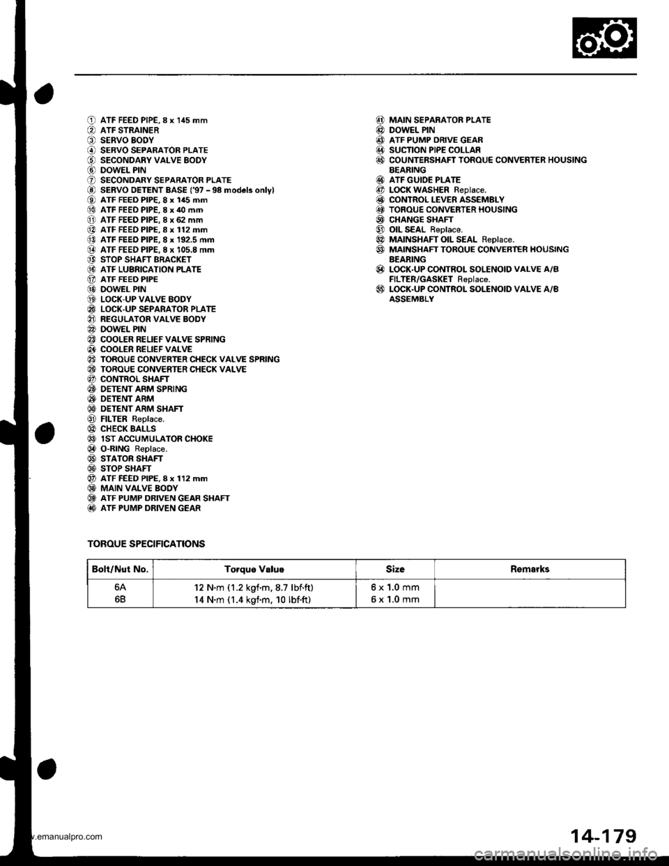
oa;\,6
G)!o,
a@,6
@o(a
@(}
@a@@@@@@@6@@)@@@@@@@@@@@@@
ATF FEED PIPE,8 x 145 mmATF STRAINERSERVO BODYSERVO SEPARATOR PLATESECONDARY VALVE EODYDOWEL PINSECONDARY SEPARATOR PLATESERVO DETENT BASE ('97 - 98 model3 onlylATF FEED PIP€, 8 x 145 mmATF FEED PIPE,8 x 40 mmATF FEED PIPE. 8 x 62 mmATF FEED PIPE.8 x 112 mmATF FEED PIPE, 8 x 192.5 mmATF FEEO PIPE. I x 105.8 mmSTOP SHAFT BRACKETATF LUBRICATION PLATEATF FEEO PIPEDOWEL PINLOCK-UP VALVE EODYLOCK-UP SEPARATOR PLATEREGULATOR VALVE BODYDOWEL PINCOOLER RELIEF VALVE SPRINGCOOLER RELIEF VALVETOROUE CONVERTER CHECK VALVE SPRINGTOROUE CONVERTER CHECK VALVECONTROL SHAFTOETENT ARM SPRINGOETENT ARMDETENT ARM SHAFTFILTER Replace.CHECK BALLSlST ACCUMULATOR CHOKEO"RING Replace.STATOR SHAFTSTOP SHAFTATF FEED PIPE, I x 112 mmMAIN VALVE BOOYATF PUMP DRIVEN GEAR SHAFTATF PUMP DRIVEN GEAR
TOROUE SPECIFICATIONS
MAIN SEPARATOR PLATEDOWEL PINATF PUMP DRIVE GEARSUCTION PIPE COLLARCOUNTERSHAFT TOROUE CONVERTER HOUSINGBEARINGATF GUIDE PLATELOCK WASHER Replace.CONTROL LEVER ASSEMBLYTOROUE CONVERTER HOUSINGCHANGE SHAFTOIL SEAL Reolace.MAINSHAFT OIL SEAL Reolace.MAINSHAFT TOROUE CONVERT€R HOUSINGBEARINGLOCK.UP CONTROL SOLENOID VALVE A/BFILTER/GASKET Replace.LOCK.UP CONTROL SOLENOID VALVE A/BASSEMBLY
@@@@@
@@@@@@@@
@
@
Bolt/Nut No.Torque ValugSizeRomarks
64
6B
12 N'm (1.2 kgf.m,8.7 lbf.ft)
14 N.m (1.4 kgf.m, 10 lbf.ft)
6x1.0mm
6x1.0mm
14-179
www.emanualpro.com