end HONDA CR-V 1998 RD1-RD3 / 1.G Workshop Manual
[x] Cancel search | Manufacturer: HONDA, Model Year: 1998, Model line: CR-V, Model: HONDA CR-V 1998 RD1-RD3 / 1.GPages: 1395, PDF Size: 35.62 MB
Page 534 of 1395
Description
Electronic Control System (cont'dl
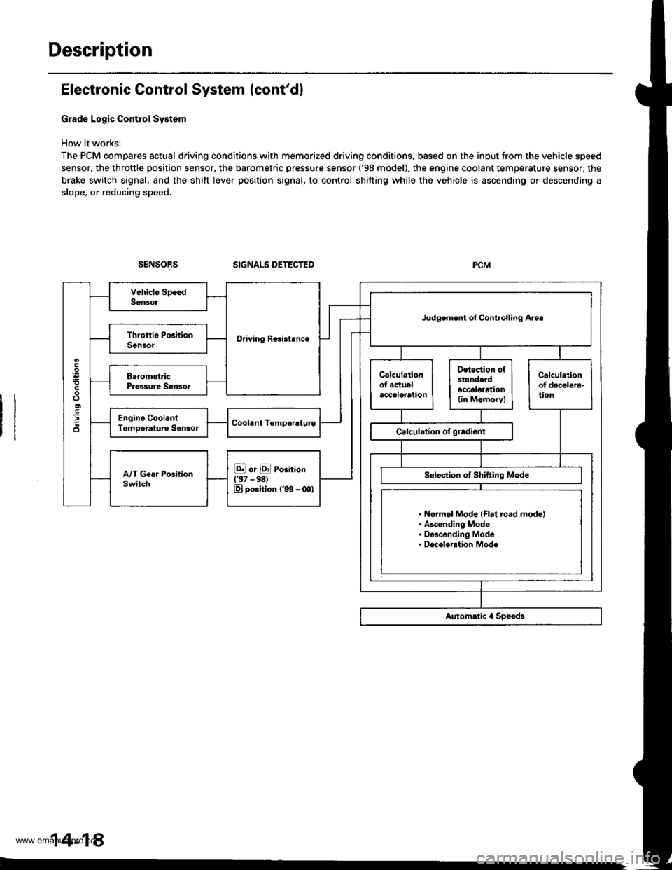
Grade Logic Control System
How it works:
The PCM compares actual driving conditions with memorized driving conditions, based on the input from the vehicle speed
sensor, the throttle position sensor, the barometric pressure sensor ('98 model). the engine coolant temperature sensor, the
brake switch signal, and the shift lever position signal, to control shifting while the vehicle is ascending or descending a
slope, or reducing speed.
SIGNALS DETECTED
Driving Rcsisl.nce
Judgemont ot Controlling Aroa
. Normal Modo {Flrt ro.d mode}. Ascending Mode. Deacending Mode. Deceleration Mode
14-14
www.emanualpro.com
Page 535 of 1395
![HONDA CR-V 1998 RD1-RD3 / 1.G Workshop Manual
Ascending Control {37 Modol}
When the PCM determines that the vehicle is climbing a hill in E] and E positions, the system extends the engagement
area of 2nd g€ar and 3rd gear to prevent the transm](/img/13/5778/w960_5778-534.png "HONDA CR-V 1998 RD1-RD3 / 1.G Workshop Manual
Ascending Control {37 Modol}
When the PCM determines that the vehicle is climbing a hill in E] and E positions, the system extends the engagement
area of 2nd g€ar and 3rd gear to prevent the transm")
Ascending Control {37 Modol}
When the PCM determines that the vehicle is climbing a hill in E] and E positions, the system extends the engagement
area of 2nd g€ar and 3rd gear to prevent the transmission from frequently shifting between 2nd and 3rd gears, and
between 3rd and 4th gears, so the vehicle can run smooth and have more power when needed.
NOTE:
. Shift schedules stored in ths PCM between 2nd and 3rd gears, and between 3rd and 4th gears. enable the PCM's fuzzy
logic to automatically select the most suitable gear according to the magnitude of 8 gradient.
t Fuzzy logic is a form of artificial intslligence that lets computers respond to changing conditions much like a human
mind would.
3RD - tlTHASCENoING MODE: UFhift Sch.dulc
- . FLAT ROAD MODE
-----------. : GRADUAL ASCENDING MODE
- - - - - : STEEPASCENDING MODEo5l)
FFN1NS
7,.,.7a
: 2ND-3RD SHIFTING CHARACTERISTICSCONTROL AREA| 3RD-aTH SHIFTING CHARACTER|SnCSCONTROL AREA
62 mph
1100 km/h)Vehicle .o..d
Asconding Conirol ('98 - 00 Mod.ls)
When the PCM determines that the vohicle is climbing a hill in E] and E positions ('98 model), and in E] position ('99 -
00 models), the system extends the engagement srea of 2nd gear and 3rd gear to prevent the transmission from frequent-
ly shifting between 2nd and 3rd gears, and between 3rd and 4th gears, so the vehicle can run smooth and have more
power when needed.
NOTE: Shift schedulss stored in the PCM between 2nd and 3rd gears, and between 3rd and 4th gears, enable to selsct the
most suitable gear according to th6 magnitude of a gradi€nt.
ASCENDING MODE: Up.hift Sch.dul.
NN : 2ND-3RD SXImNG CHARACTERISTICS- GoNTRoLAREA
VVVVVZ:IRD-ITHSHIFnNGCHARACTERISTICS- cot{TRoL AREA
850
o
6:l mph11fl) km/hl
(cont'd)
2ND - 3RD
2ND + 3RD 3RD + 4TH
Vahicl. sDctd
14-19
www.emanualpro.com
Page 536 of 1395
Description
Electronic Control System (cont'd)
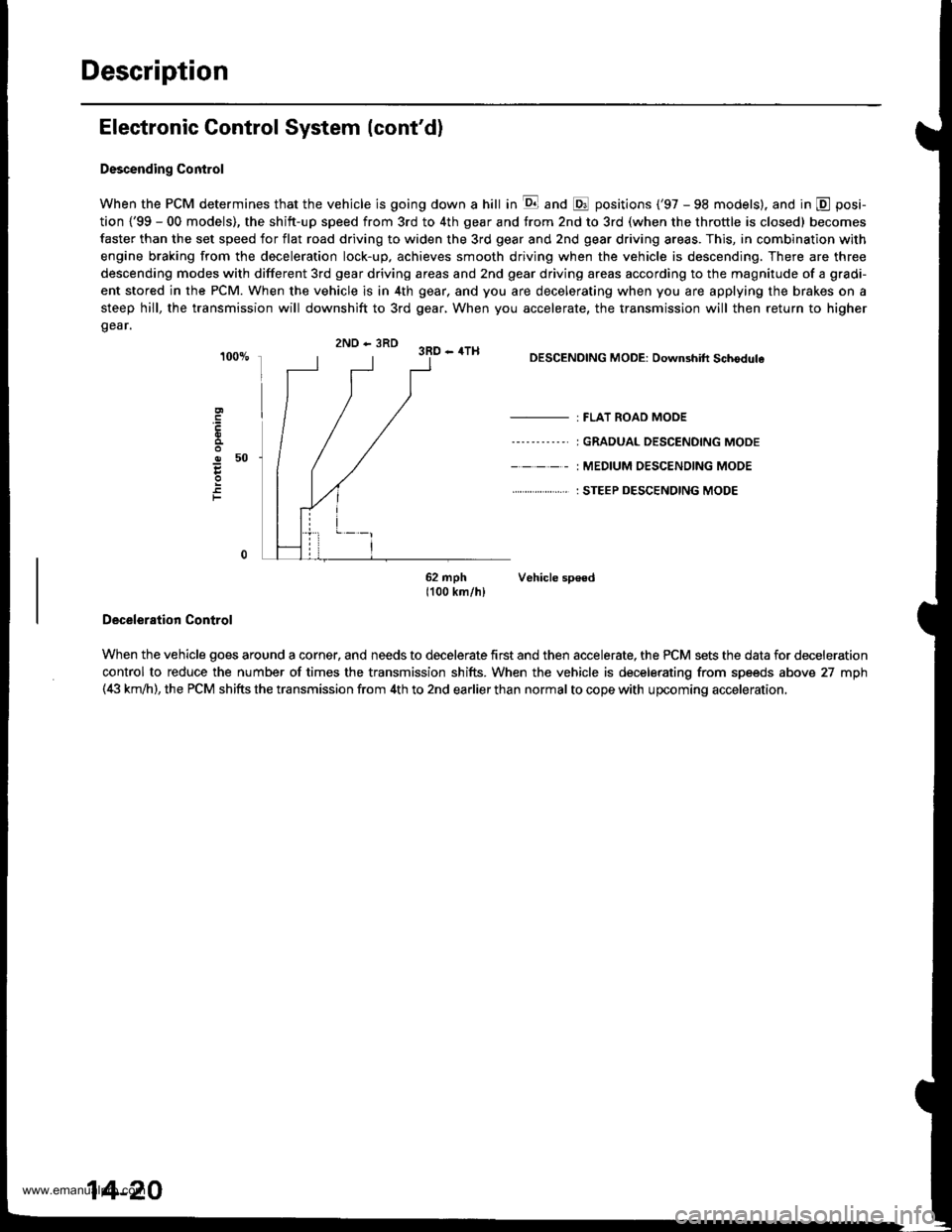
Descending Control
When the PCM determines that the vehicle is going down a hill in E and @ positions ('97 - 98 models). and in @ posi-
tion {'99 - 00 models), the shitt-up speed from 3rd to 4th gear and from 2nd to 3rd (when the throttle is closed) becomes
faster than the set speed for flat road driving to widen the 3rd gear and 2nd gear driving areas. This, in combination with
engine braking from the deceleration lock-up, achieves smooth driving when the vehicle is descending. There are three
descending modes with different 3rd gear driving areas and 2nd gear driving areas according to the magnitude of a gradi-
ent stored in the PCM. When the vehicle is in 4th gear, and you are decelerating when you are applying the brakes on a
steep hill, the transmission will downshift to 3rd gear, When you accelerate, the transmission will then return to higher
gear.
2ND - 3RD 3RD - 4TH
o50
F
DESCENDING MODE: Downshift Schodule
- : FLAT ROAD MODE
----'-----' I GRADUAL DESCENDING MODE
- - - - - : MEDIUM OESC€NOING MODE
. . ... : STEEP DESCENDING MODE
62 mph Vehicle sp€ed1100 km/hl
Deceleration Control
When the vehicle goes around a corner, and needs to decelerate first and then accelerate, the PCM sets the data for deceleration
control to reduce the number of times the transmission shifts. When the vehicle is decelerating from speeds above 27 mph(4i| km,ih), the PCM shifts the transmission from 4th to 2nd earlier than normal to cope with upcoming acceleration,
14-20
www.emanualpro.com
Page 540 of 1395
Description
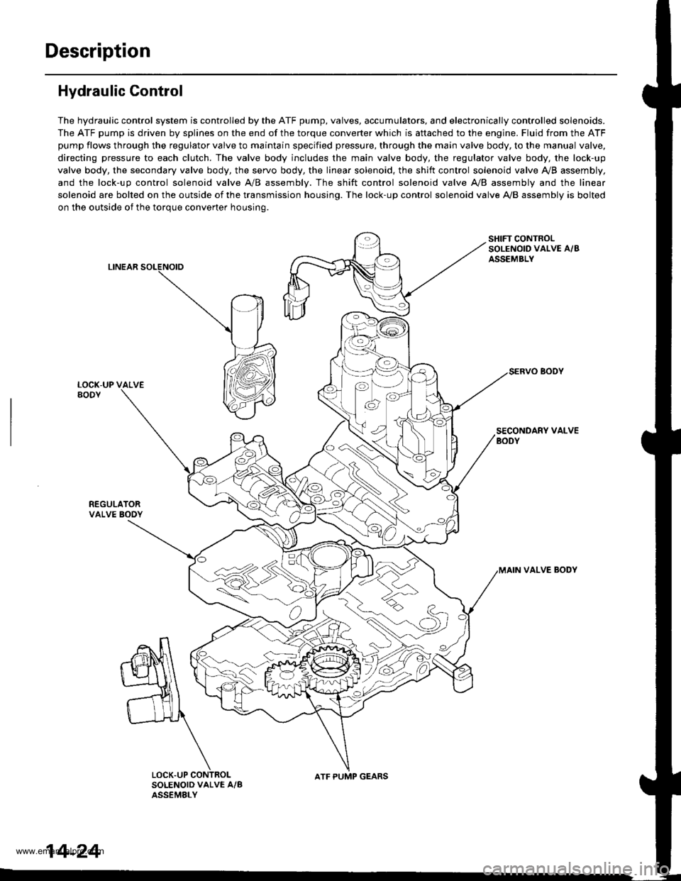
Hydraulic Control
The hydraulic control system is controlled by the ATF pump, valves, accumulators, and electronically controlled solenoids.
The ATF pump is driven by splines on the end of the torque converter which is aftached to the engine. Fluid from the ATF
pump flows through the regulator valve to maintain specified pressure, through the main valve body, to the manual valve,
directing pressure to each clutch. The valve body includes the main valve body, the regulator valve body, the lock-up
valve body, the secondary valve body, the servo body, the linear solenoid, the shift control solenoid valve Ay'B assembly,
and the lock-up control solenoid valve A/B assembly. The shift control solenoid valve A,/B assembly and the linear
solenoid are bolted on the outside of the transmission housing. The lock-up control solenoid valve A,/B assembly is bolted
on the outside of the torque converter housing.
LINEAR
SHIFT CONTROLSOLENOID VALVE A/BASSEMBLY
SECONDARY VALVEBODY
REGULATORVALVE BOOY
VALVE BODY
SOLENOID VALVE A/BASSEMELY
N
ATF PUMP GEARS
14-24
www.emanualpro.com
Page 543 of 1395
Regulator Valve
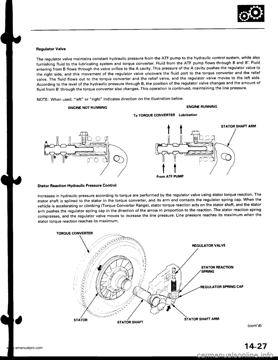
The regulator valve maintains constant hydraulic pressure from the ATF pump to the hydraullc control system, while also
furnishing fluid to the lubricating system and torque converter. Fluid from the ATF pump flows through B and B'. Fluid
entering from B flows through the valve orifice to the A cavity. This pressure of the A cavity pushes the regulator valve to
the right side. and this movement of the regulator valve uncovers the fluid port to the torque converter and the relief
valve. The fluid flows out to the torque converter and the relief valve, and the regulator valve moves to the left side.
According to the level of the hydraulic pressure through B, the position of the regulator valve changes and the amount of
fluid from B,through the torque converter also changes. This operation is continued, maintaining the line pressure.
NOTE; When used, "|eft" or "right" indicates direction on the illustration below.
ENGINE NOT RUNNING
STATOR SHAFT ABM
Stator Reaction Hydraulic Pressurs Control
Increases in hydraulic pressure according to torque are performed by the regulator valve using stator torque reaction. The
stator shaft is splined to the stator in the torque converter, and its arm end contacts the regulator spring cap When the
vehicle is accelerating or climbing (Torque Converter Range), stator torque reaction acts on the stator shaft, and the stator
arm pushes the regulator spring cap in the direction of the arrow in proportion to the reaction. The stator reaction spring
compresses, and the regulator valve moves to increase the line pressure. Line pressure reaches its maximum when the
stator torque reaction reaches its maximum.
TOROUE CONVERTER
REGULATON VALVE
STATOR REACTION
TOR SPRING CAP
(cont'd)
ENGINE RUNNING
To TOROUE CONVERTER Lubtication
STATONSTASHAFTATOF SHAFT ARM
14-27
www.emanualpro.com
Page 547 of 1395
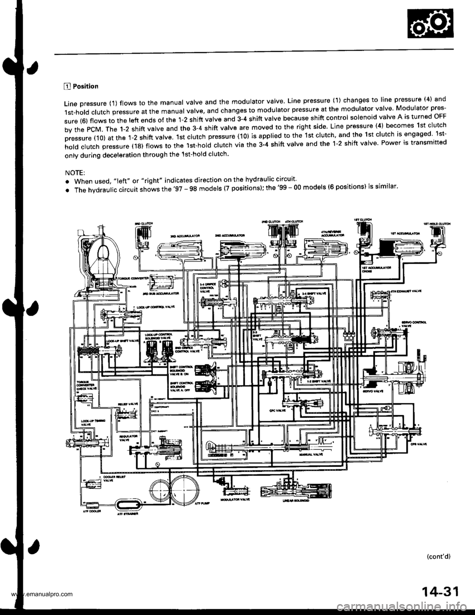
B Position
Line pressure {1) flows to the manual valve and the modulator valve, Line pressure (1) changes to line pressure (4) and
1st-hold clutch pressure at the manual valve, and changes to modulator pressure at the modulator valve Modulator pres-
sure {6) flows to the left ends of the 1-2 shift valve and 3-4 shift valve because shift control solenoid valve A is turned oFF
by the PcM. The 1-2 shift valve and the 3-4 shift valve are moved to the right side. Line pressure (4) becomes 1st clutch
pressure (10) at the 1-2 shift valve. 1st clutch pressure (10) is applied to the 1st clutch, and the 1st clutch is engaged lst-
hold clutch pressure (18) flows to the lst-hol; clutch via the 3-4 shift valve and the 1-2 shift valve Power is transmitted
only during deceleration through the 1st-hold clutch.
NOTE:
. When used, "left" or "right" indicates direction on the hydraulic circuit'
. The hvdraulic circuit shows the'97 - 98 models (7 positions); the '99 - O0 models (6 positions) is similar'
(cont'd)
14-31
www.emanualpro.com
Page 549 of 1395
![HONDA CR-V 1998 RD1-RD3 / 1.G Workshop Manual
E] or E Position (97 - 98 Models), and D Position (99 - 00 Modelsl
1. lst Gear
Fluid flow through the torque converter circuit is the same as in E] position. Line pressure flows to the manual valve](/img/13/5778/w960_5778-548.png "HONDA CR-V 1998 RD1-RD3 / 1.G Workshop Manual
E] or E Position (97 - 98 Models), and D Position (99 - 00 Modelsl
1. lst Gear
Fluid flow through the torque converter circuit is the same as in E] position. Line pressure flows to the manual valve")
E] or E Position ('97 - 98 Models), and D Position ('99 - 00 Modelsl
1. lst Gear
Fluid flow through the torque converter circuit is the same as in E] position. Line pressure flows to the manual valve
and the modulator valve. Line pressure changes to modulator pressure (6) at the modulator valve and to line pressure
{4) at the manual valve. Modulator pressure (6) flows to the left end of the 1-2 shift valve and the 3-4 shift valve
because shift control solenoid valve A is turned oFF and B is turned oN by the PcM. The 1-2 shift valve is moved to
the right side. Line pressure {4) changes to 'lst clutch pressure (10} at the 1-2 shift valve and the orifice The 1st clutch
pressure (10) is applied to the 1st clutch and the 1st accumulator; the vehicle will move as the engine power is trans-
mitted.
NOTE:
. When used, "left" or "right" indicates direction on the hydraulic circuit.
. The hvd rau lic circuit shows th e '97 - 98 models (7 positions); the '99 - 00 models {6 positions) issimilar.
(cont'dl
14-33
www.emanualpro.com
Page 550 of 1395
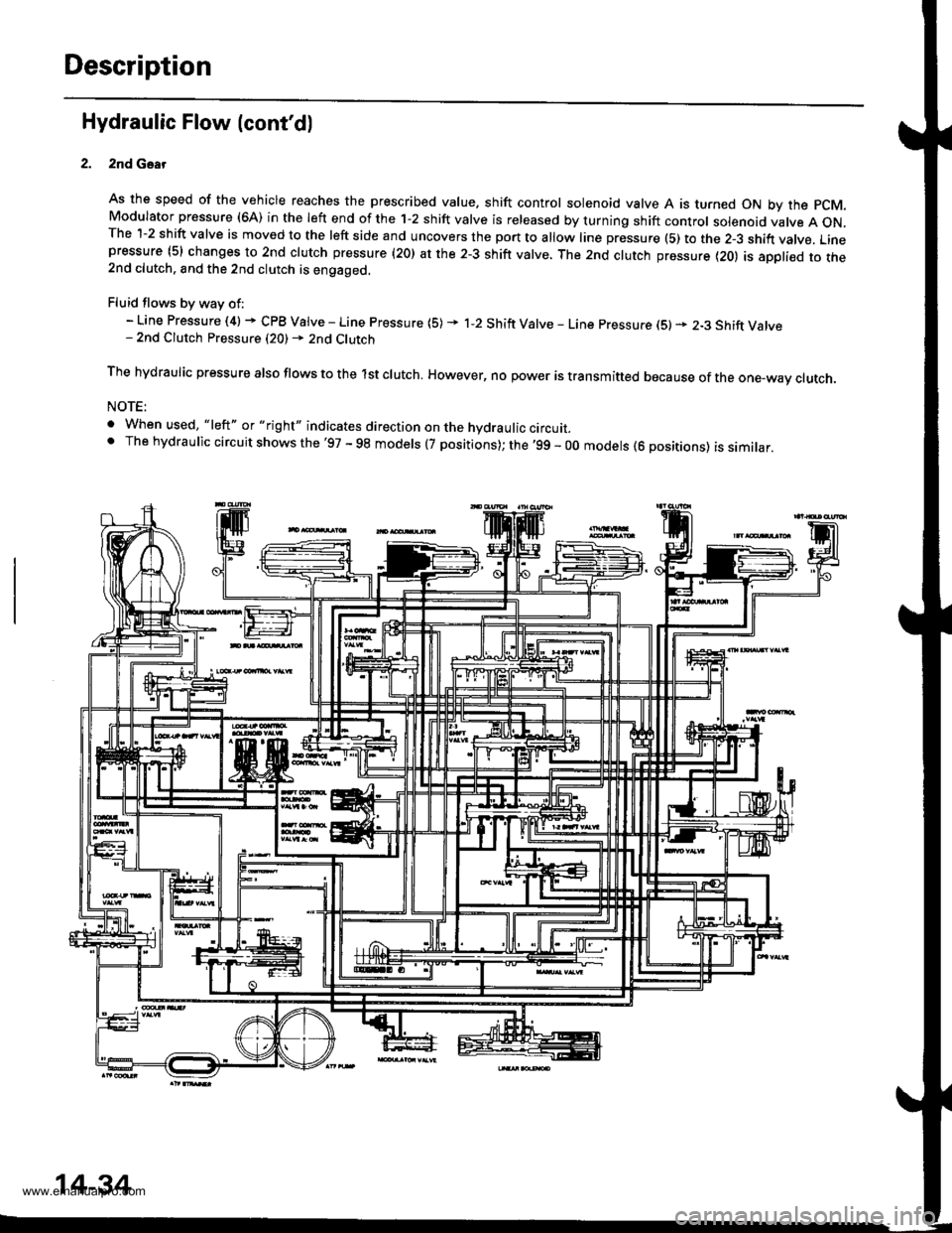
Description
Hydraulic Flow (cont'dl
2nd Gsar
As the speed of the vehicle reaches the prescribed value. shift control solenoid valve A is turned ON by the pCM.Modulator pressure (6A) in the left end of the 1-2 shift valve is released by turning shift control solenoid valve A ON.The 1-2 shift valve is moved to the left side and uncovers the port to allow line pressure (5) to the 2-3 shift vatve. Linepressure (5) changes to 2nd clutch pressure (20) at the 2-3 shift valve, The 2nd clutch pressure {20) is appli€d to the2nd clutch. and the 2nd clutch is engaged.
Fluid flows by way of:- Line Pressure (4) + CPB Valve - Line Pressure (5) * 1-2 Shift Valve - Line pressure (S) * 2-3 Shift Valve- 2nd Clutch Pressure (20) - 2nd Clutch
The hydraulic pressure also flows to the lst clutch. However, no power is transmitted because of the one-wav ctutch.
NOTE:
. When used, "|eft" or "right" indicates direction on the hydraulic circurr_' The hydraulic circuit shows the'97 - 98 models (7 positions); the '99 - 00 models (6 positions) is similar,
14-34
www.emanualpro.com
Page 551 of 1395
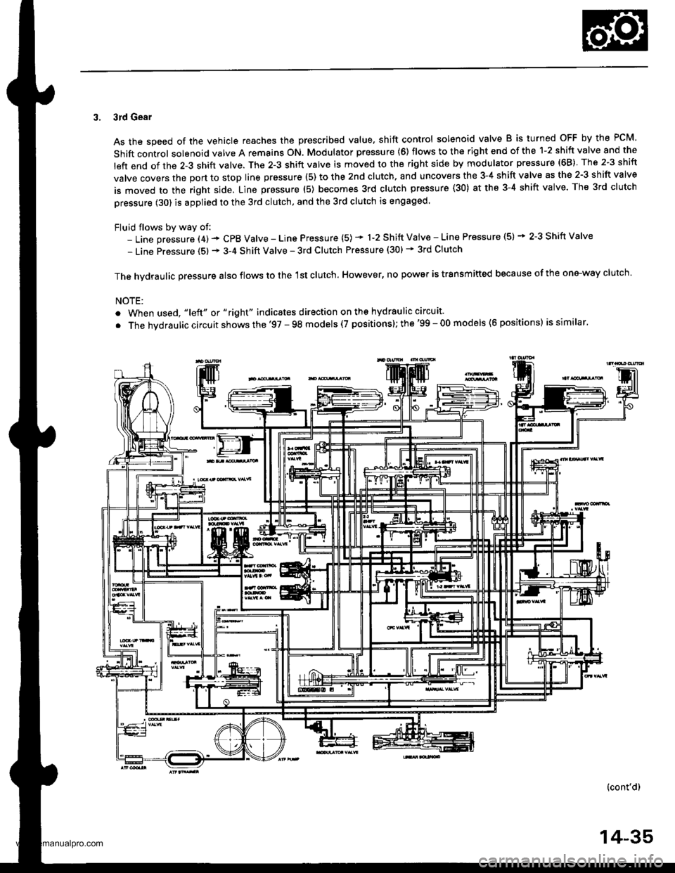
3. 3rd Gear
As the speed of the vehicle reaches the prescribed value. shift control solenoid valve B is turned OFF by the PCM.
Shift control solenoid valve A remains ON. Modulator pressure (6) flows to the right end of the 1-2 shift valve and the
left end of the 2-3 shift valve. The 2-3 shift valve is moved to the right side by modulator pressure (68) The 2-3 shift
valve covers the port to stop line prsssure (5) to the 2nd clutch. and uncovers the 3-4 shift valve as the 2-3 shift valve
is moved to the right side, Line pressure (5) becomes 3rd clutch pressure (30) at the 3-4 shift valve. The 3rd clutch
pressure (30) is applied to the 3rd clutch, and the 3rd clutch is engaged.
Fluid flows by way of:- Line pressure (4) - CPB Valve - Line Pressure (5) * 1-2 Shift Vaiv€ - Line Pressure (5) * 2-3 Shift Valve
- Line Pressure (5) * 3-4 Shift Valve - 3rd Clutch Pressure (30) * 3rd Clutch
The hvdraulic Dressure also flows to the 1st clutch. However, no power is trsnsmitted because of the one-way clutch.
NOTE:
. When used, "|eft" or "right" indicates direction on ths hydraulic circuit.
. The hvdraulic circuit shows the '97 - 98 models (7 positions); the'99 - 00 models (6 positions) is similar.
(cont'd)
14-35
www.emanualpro.com
Page 552 of 1395
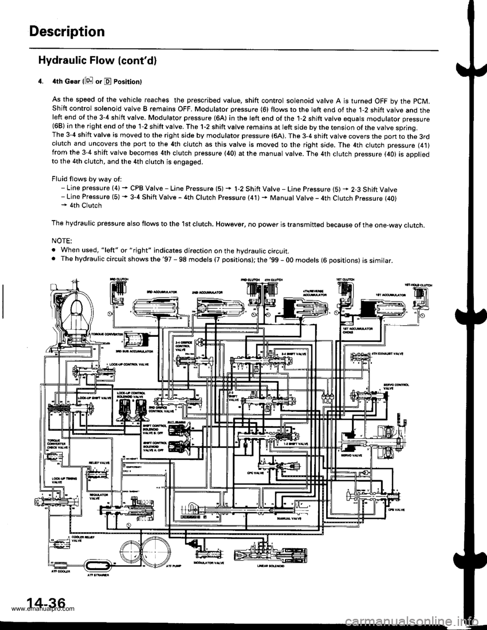
Description
Hydraulic Flow (cont'd)
4th Gear llQ! or E Posirion)
As the speed of the vehicle reaches the prescribed value. shift control solenoid valve A is turned OFF by the pCM,
Shift control solenoid valve B remains OFF. Modulator pressure (6) flows to the left end of the 1-2 shift valve and theleft end of the 3-4 shift valve. Modulator pressure (64) in the left end of the 1-2 shift valve equals modulator pressure(68) in the right end of the 1-2 shift valve. The 1-2 shift valve remains at left side by the tension of the valve spring.The 3-4 shift valve is moved to the right side by modulator pressure (6A). The 3-4 shift valve covers the pon to the 3rdclutch and uncovers the port to the 4th clutch as this valve is moved to the right side, The 4th clutch pressure (41)from the 3-4 shift valve becomes 4th clutch pressure (40) at the manual valve. The 4th clutch pressure (40) is appliedto the 4th clutch, and the 4th clutch is engaged.
Fluid flows by way of:- Line pressure (4) + CPB Valve - Line Pressure (5) + l-2 Shift Valve - Line Pressure {5) * 2-3 Shift Valve- Line Pressure (5) + 3-4 Shift Valve - 4th Clutch Pressure (41) + Manual Valve - 4th Clutch Pressure (40)+ 4th Clutch
The hydraulic pressure also flows to the lst clutch. However, no power is transmitted because of the one-wav clutch.
NOTE:
. When used, "lelt" or " tight" indicates direction on the hydraulic circuit.. The hydrau lic circuit shows the '97 - 98 models (7 positions); the '99 - 0O models (6 oositions) issimilar.
14-36
www.emanualpro.com