end HONDA CR-V 1998 RD1-RD3 / 1.G Workshop Manual
[x] Cancel search | Manufacturer: HONDA, Model Year: 1998, Model line: CR-V, Model: HONDA CR-V 1998 RD1-RD3 / 1.GPages: 1395, PDF Size: 35.62 MB
Page 733 of 1395
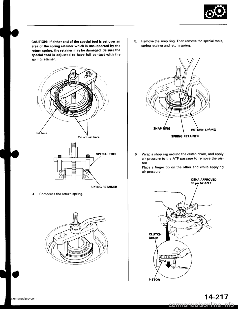
CAUTION: lf either end ot the special tool issetover an
area of the spring retainer which is unsupported by the
return spring, the retainer may be damaged. B€ sure the
special tool is adiusted to have lull contact with the
spring retainer.
SPRING RETAINER
4. Compress the return spring.
Do not s6t h6re.
5. Remove the snap ring, Then remove the special tools,
spring retainer and return spring.
Wrap a shop rag around the clutch drum, and apply
air pressure to the ATF passage to remove the pis-
ton.
Place a finger tip on the other end while applying
arr pressure.
OSHA.APPROVED
SPRIlIG RETAINER
14-217
www.emanualpro.com
Page 735 of 1395
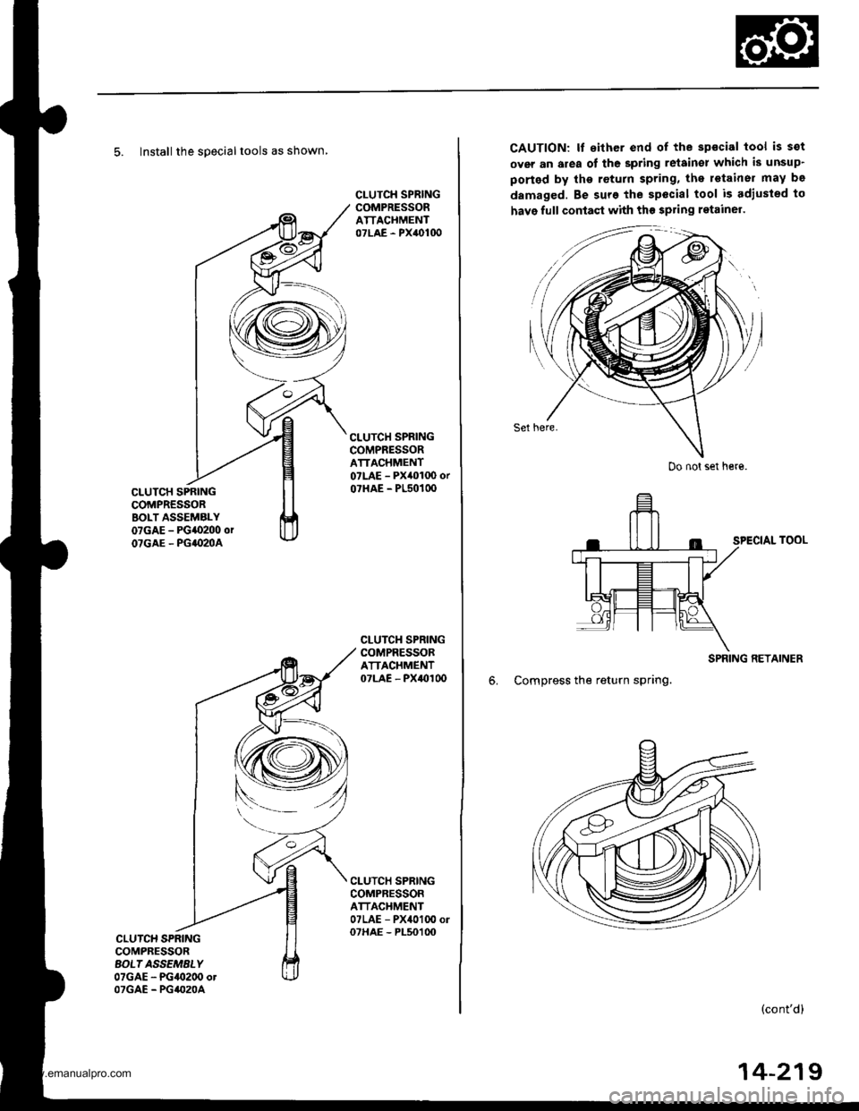
5. Install the specialtools as shown
CLUTCH SPRINGCOMPRESSORBOLT ASSEMALY07GAE - PG{0200 orOTGAE - PG|(IMA
CLUTCH SPRINGCOMPRESSORATTACHMENT07LAE - PX40100
CLUTCH SPRINGCOMPRESSORATTACHMENT07LAE - PX40100 orO?HAE - PL5O1OO
CLUTCH SPRINGCOMPRESSORATTACHMENT07LAE - PXaOI 0o
CLUTCH SPRINGCOMPRESSORATTACHMENT07LAE - PX4010O ol07HAE - PL50100CLUTCH SPRINGCOMPBESSORAOL| ASSEMALY07GAE - PG/9t200 otOTGAE - PG/(,20A
CAUTION: It sither end of the spscial tool is sot
over an area of the spring retain€l which is unsup'
ported by the return spring, the retainer may be
damaged. Be sure the special tool is adiusted to
have full contaqt with th€ spring ratainel.
Set here.
SPECIAL TOOL
SPRING RETAINER
6. Compress the return spring.
(cont'd)
Do not set here.
14-219
www.emanualpro.com
Page 736 of 1395
Clutch
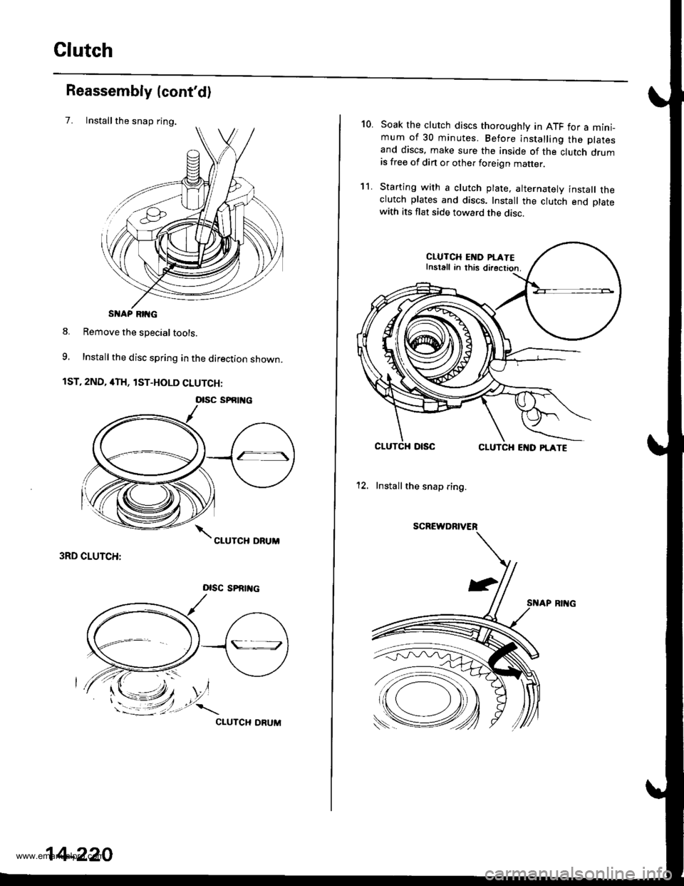
Installthe snap ring.
Reassembly (cont'd)
7.
S AP RIIG
8. Remove the special tools.
9, Install the disc spring in the direction shown.
1ST, 2ND, 4TH, lST-HOLD CLUTCH:
3RD CLUTCH:
Dlsc sPRrrtc
CIUTCH ORUM
otsc sPfitl{c
14-220
10.Soak the clutch discs thoroughly in ATF for a mini_mum of 30 minutes. Before installing the platesand discs, make sure the inside of the clutch drumis free of din or other foreign matter
Starting with a clutch plate, alternatelv install theclutch plates and discs. Install the clutch end platewith its flat side toward the disc.
CLUTCH EI{D PI.ATEInstall in this directior.
CLUTCHCLUTCH EI{D PLATE
12. Install the snap ring.
SCREWDRIVER
't1.
www.emanualpro.com
Page 737 of 1395
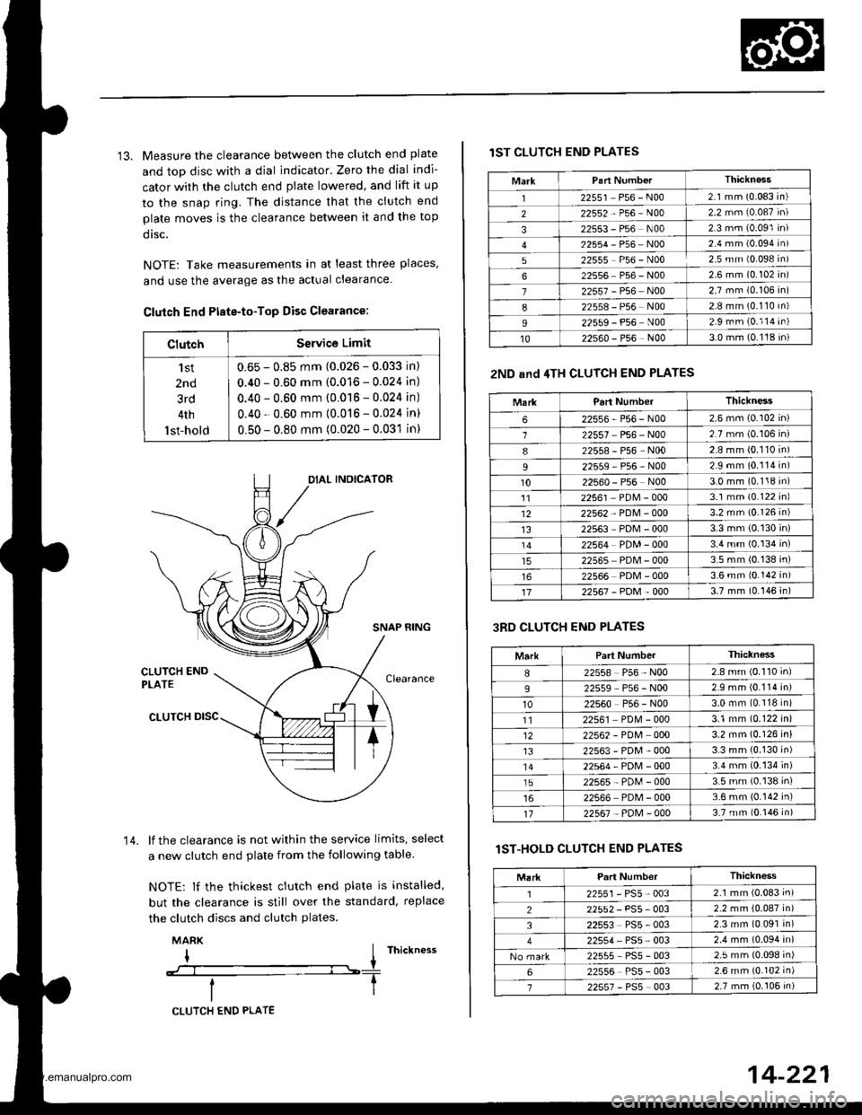
13. Measure the clearance between the clutch end plate
and top disc with a dial indicator. Zero the dial indi-
cator with the clutch end plate lowered, and lift it up
to the snap ring. The distance that the clutch end
plate moves is the clearance between it and the top
dtsc.
NOTE: Take measurements in at least three places'
and use the average as the actual clearance.
Clutch End Ptate-to-Top Disc Clearance:
ClutchService Limit
'l st
2nd
3rd
4th
lst-hold
0.65 - 0.85 mm (0.026 - 0.033 in)
0.40 - 0.60 mm (0.016 - 0.024 in)
0.40 - 0.60 mm (0.016 - 0.024 in)
0.40 - 0.60 mm (0.016 - 0.024 in)
0.50 - 0.80 mm (0.020 - 0.031 in)
SNAP RING
lf the clearance is not within the service limits, select
a new clutch end plate from the following table
NOTE: lf the thickest clutch end plate is installed,
but the clearance is still over the standard, replace
the clutch discs and clutch plates.
MARK
I I rnictness
--:--l----T
14.
CLUTCH END PLATE
14-221
lST CLUTCH END PLATES
2ND and 4TH CLUTCH END PLATES
3RD CLUTCH END PLATES
lST-HOLD CLUTCH END PLATES
MarkThicknass'I22551 P56 - N002.1 mm (0.083 in)
222552-P56-N002.2 mm (0.087 in)
322553 - P56 N002 3 mm (0.091 in)
22554-P56-NOo2.4 mm (0.094 in)
522555 P56 - N002.5 mm {0.098 in)
622556 P56 - N002 6 mm (0.102 in)
722557 - P56 N002.7 mm (0.106 in)
822558 - P56 N002.8 mm (0.110 in)
I22559 - P56 N002.9 rnm (0.114 in)
1022s60 - P56 N003.0 mm (0.118 in)
MarkParl NumberThickness
622556-P56-N002.6 mm (0.102 in)
122557 P56 - N002.7 mm (0.106 in)
822558-P56-N002.8 mm (0.110 in)
22559-P56-N002.9 mm (0.114 in)
1022560 - P56 N003.0 mm (0.118 in)'1122561 PDM - 0003.1 mm (0.122 inl
1222562 - PDM - 0003.2 mm {0.126 in)
1322563 PDM - 0003.3 mm (0.130 in)
22564 PDM - 0003.4 mm (0.134 in)
22565 PDM - 0003.5 mm (0.138 in)
22566 PDM - 0003.6 mm 10.142 in)
1722567-PDM-0003.7 mm (0.146 in)
MarkPart NumberThiclness
I22558 P56 - N002.8 mm (0.110 inl
922559 P56 - N002.9 mm (0.114 in)
1022560 P56 - N003.0 mm (0.118 in)
1122561 PD[4 - 0003.1 mm (0.122 in)
1222562 - PDM 0003.2 mm (0.126 in)
t322563-PDM-0003.3 mm (0.130 in)'1422564-PDN4-0003.4 mm (0.134 in)
1522565-PD[,l-0003.5 mm (0.138 in)
22566 PDM - 0003.6 mm (0.142 in)'t122567 - PoM - 0003.7 mm {0.146 in)
Thickness
2255r-PS5-0032.1 mm (0.083 in)
22552 - PS5- 0032.2 mm {0.087 in)
322553 PS5 - 0032.3 mm (0.091 in)
22554, PS5 - 0032.4 mm (0.094 in)
22555 PS5 - 0032.5 mm (0.098 in)
622556 PS5 - 0032.6 mm {0.102 in)
722557 - PSs 0032.7 mm (0.106 in)
www.emanualpro.com
Page 740 of 1395
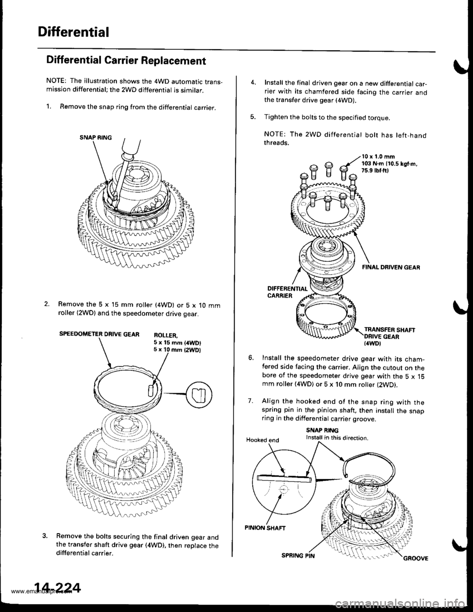
Differential
Differential Carrier Replacement
NOTE: The illustration shows the 4WD automatic trans-mission differential; the 2WD differential is similar.
1. Remove the snap ring from the differential carrier.
Remove the 5 x 15 mm roller (4WD) or 5 x 10 mmroller (2WDl and the speedometer drive gear.
SPEEDOMETER DRIVE GEAR RoI I FP
Remove the bolts securing the final driven gear andthe transfer shaft drive gear (4WD), then replace thedifferential carrier.
5 x 15 mm (/tWD)5 x 10 mm {2WDl
14-224
SPRING PINGROOVE
Install the final driven gear on a new differential car-rier with its chamfered side facing the carrier andthe transfer drive gear (4WD),
Tighten the bolts to the specified torque.
NOTE: The 2WD differentiat bolt has left-handthreads,
10 x 1.0 mm103 N.m 110.5 kd.m,7s.9 rbr.ft)
7.
FINAL DRIVEN GEAR
TRANSFER SHAFT
Install the speedometer drive gear with its cham-fered side facing the carrier. Align the cutout on thebore of the speedometer drive gear with the 5 x 15mm roller (4WD) or 5 x 10 mm roller (2WD).
Align the hooked end of the snap ring with thespring pin in the pinion shaft. then install the snaoring in the differential carrier groove
SNAP RINGInstall in this direction.Hooked end
PINION SHAFT
{4WDl
www.emanualpro.com
Page 743 of 1395
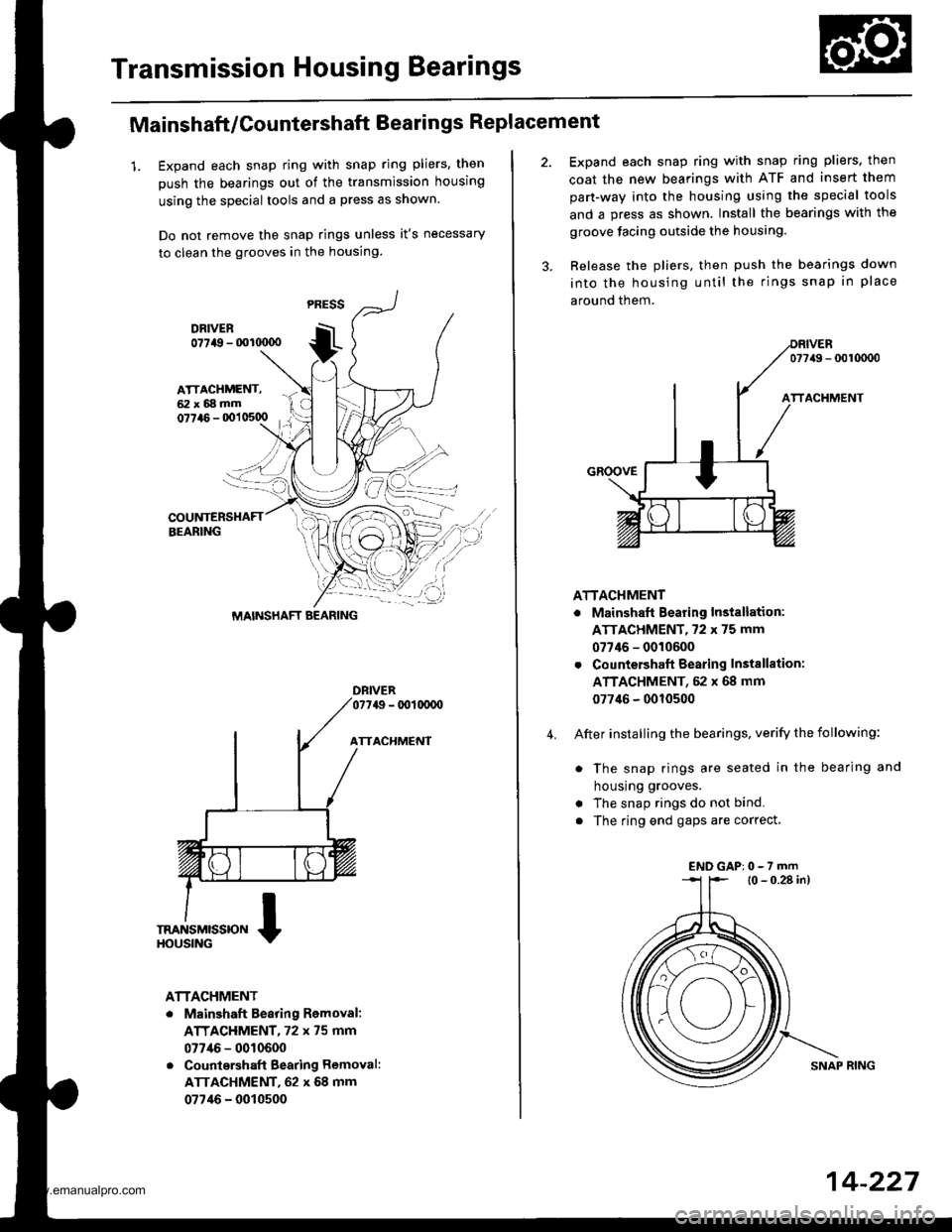
Transmission Housing Bearings
Mainshaft/Countershaft Bearings Replacement
1. Expand each snap ring with snap ring pliers, then
push the bearings out of the transmission housing
using the special tools and a press as shown.
Do not remove the snap rings unless it's necessary
to clean the grooves in the housing.
DFIVER077a9 - 001(xx)o
ATTACHMENT
ATTACHMENT
. Mainshaft Bearing Romoval:
ATTACHMENT, 72 x 75 mm
077/16 - 0010600
. Countqrshaft Bearing Removal:
ATTACHMENT, 62 x 68 mm
07746 - 0010500
MAINSHAFT BEARING
4.
Expand each snap ring with snap ring pliers, then
coat the new bearings with ATF and insert them
part-way into the housing using the special tools
and a press as shown. Install the bearings with the
groove facing outside the housing.
Release the pliers, then push the bearings down
into the housing until the rings snap in place
around them.
077/49 - 0010000
ATTACHMENT
. Mainshaft Bearing Installation:
ATTACHMENT,72 x 75 mm
07746 - 0010600
. Countershaft Bearing Instsllation:
ATTACHMENT, 52 x 68 mm
077'16 - 0010500
After installing the bearings, verify the following:
. The snap rings are seated in the bearing and
housrng grooves.
. The snap rings do not bind.
. The ring end gaps are correct,
l0 - 0.28 in)
SNAP RING
ENDGAP:0-7rnm
14-227
www.emanualpro.com
Page 744 of 1395
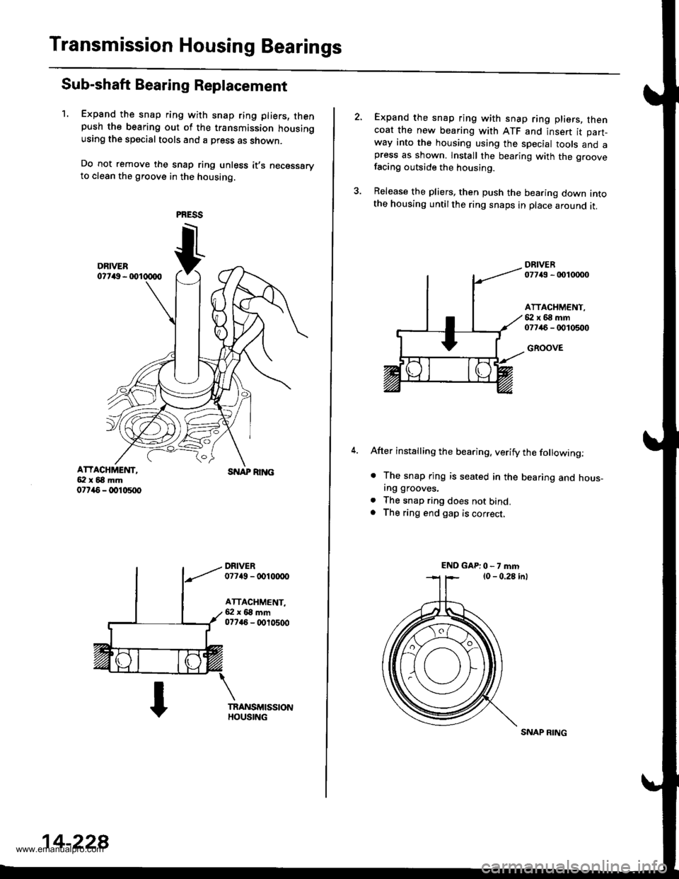
Transmission Housing Bearings
Sub-shaft Bearing Replacement
1. Expand the snap ring with snap ring pliers, thenpush the bearing out of the transmission housingusing the special tools and a press as shown.
Do not remove the snap ring unless it,s necessaryto clean the groove in the housing.
ATTACHMEI{T,5:l x 68 mm07r{5 - @10500
SNAP RI]TG
DRIVER07749 - tDl(xx)o
ATTACHMENT,6:l x 68 mm077a6 - (X,r0500
14-228
SNAP RING
Expand the snap ring with snap ring pliers, thencoat the new bearing with ATF and insert it part-way into the housing using the special tools and apress as shown. lnstall the bearing with the groovefacing outside the housing.
Release the pliers, then push the bearing down intothe housing untilthe ring snaps in place around it.
DRIVER07743 - 0010mo
ATTACHMENT,{i:l x 68 mm07746 - 0010500
GROOVE
After installing the bearing, verify the following:
. The snap rjng is seated in the bearing and hous_ing grooves.
. The snap ring does not bind.. The ring end gap is correct,
ENDGAP:0-7mm
www.emanualpro.com
Page 749 of 1395
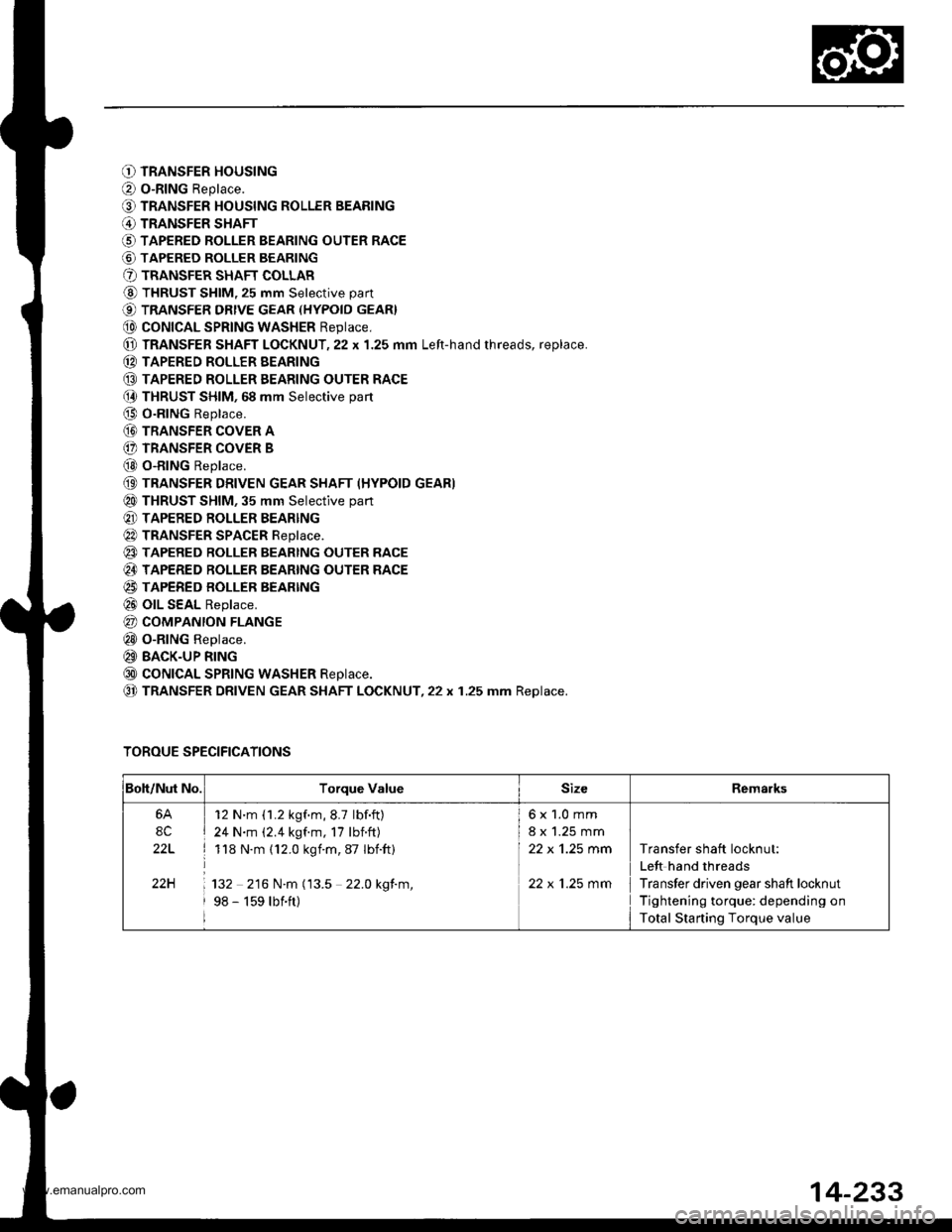
O TRANSFER HOUSING
O o-RING Replace.
O TRANSFER HOUSING ROLLER BEARING
@ TRANSFER SHAFT
O TAPERED ROLLER BEARING OUTER RACE
@ TAPERED ROLLER BEARING
O TRANSFER SHAFT COLLAR
@ THRUST SHIM, 25 mm Selective part
€) TRANSFER DRtvE GEAR (HYPoID GEAR}
@ coNtcAL SPRtNG WASHER Reptace,
@ TRANSFER SHAFT LOCKNUT,22 x 1.25 mm Left-hand rhreads, replace.
(D TAPERED ROLLER EEARING
@ TAPERED ROLLER EEARING OUTER RACE(} THRUST SHIM, 68 mm Selective part
@ O-RING Replace.
@ TRANSFER coVER A
(} TRANSFER COVER B
@ o-RING Replace.
(9 TRANSFER DRIVEN GEAR SHAFT (HYPOID GEAR)
@ THRUST SHIM, 35 mm Selective part
@ TAPERED ROLLER BEARING
@ TRANSFER SPACER Reptace.
@ TAPERED RoLLER BEARTNG OUTER RACE
@ TAPERED ROLLER BEARING OUTER RACE
@ TAPERED BOLLER BEARTNG
@ olL SEAL Replace.
@ COMPANION FLANGE
@ o-RING Replace.
@ BACK-UP RING
@ coNtcAL SPRtNG WASHER Reptace.
@ TRANSFER DRIVEN GEAR SHAFT LOCKNUT,22 x 1.25 mm Replace.
TOROUE SPECIFICATIONS
Boh/Nut No.Torque ValueSizeRemarks
6A
8C
22L
22H
12 N'm (1.2 kgf.m,8.7 lbf.ft)
24 N.m (2.4 kgf.m, 17 lbnft)
118 N.m (12.0 kgim,87 Ibift)
132 216 N.m (13.5 22.0 kgf.m,
98 - 159 lbift)
6x1.0mm
8 x 1.25 mm
22 x 'l.25 mm
22 x 1.25 mm
Transfer shaft locknut:
Left hand threads
Transfer driven gear shaft locknut
Tightening torque: depending on
Total Starting Torque value
14-233
www.emanualpro.com
Page 769 of 1395
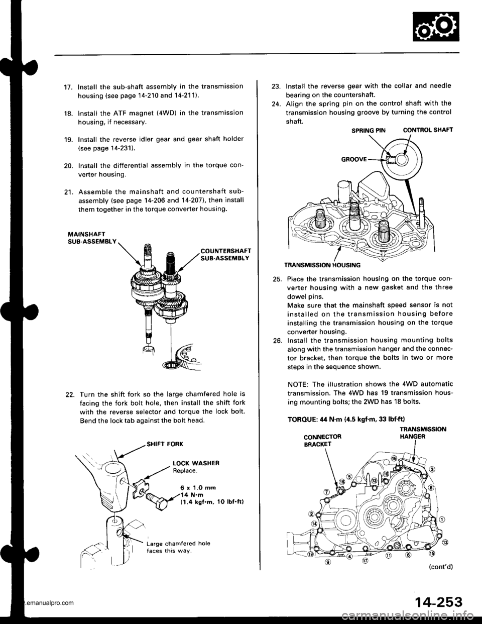
17.
18.
19.
20.
21.
Install the sub-shaft assembly in the transmission
housing (see page 14-210 and 14-2'111.
lnstall the ATF magnet (4WD) in the transmission
housing, if necessary.
Install the reverse idler gear and gear shaft holder
(see page 14-231).
Install the differential assembly in the torque con-
verter housing.
Assemble the mainshaft and countershaft sub-
assembly (see page 14-206 and 14 207],, then install
them together in the torque converter houslng.
COUNTERSHAFTSUB-ASSEMBLY
Turn the shift fork so the large chamfered hole is
facing the fork bolt hole. then install the shift fork
with the reverse selector and torque the lock bolt.
Bend the lock tab against the bolt head.
SHIFI FORK
LOCK WASHERBeplace.
6 r 'l.O mm4 N.m(1.4 ksl.m. 1O lbt.ft)
Large chamfered hole
24.
Install the reverse gear with the collar and needle
bearing on the countershatt.
Align the spring pin on the control shaft with the
transmission housing groove by turning the control
shaft.
SPRING PIN CONTROL SHAFT
TRANSMISSION HOUSING
25. Place the transmission housing on the torque con-
verter housing with a new gasket and the three
dowel pins,
Make sure that the mainshaft speed sensor is not
installed on the transmission housing before
installing the transmission housing on the torque
converter housing.
26. Install the transmission housing mounting bolts
along with the transmission hanger and the connec-
tor bracket, then torque the bolts in two or more
steos in the seouence shown.
NOTE: The illustration shows the 4WD automatic
transmission. The 4WD has 19 transmission hous-
ing mounting bolts; the 2WD has 18 bolts.
TOROUE: 44 N.m {,[.5 kgf.m, 33 lbf'ft)
{cont'd)
14-253
SPRING PIN
TNANSMISSION
www.emanualpro.com
Page 770 of 1395
Transmission
28.
Reassembly (cont'd)
PARX GEAR
ONE.WAY CLUTCH
BEARING
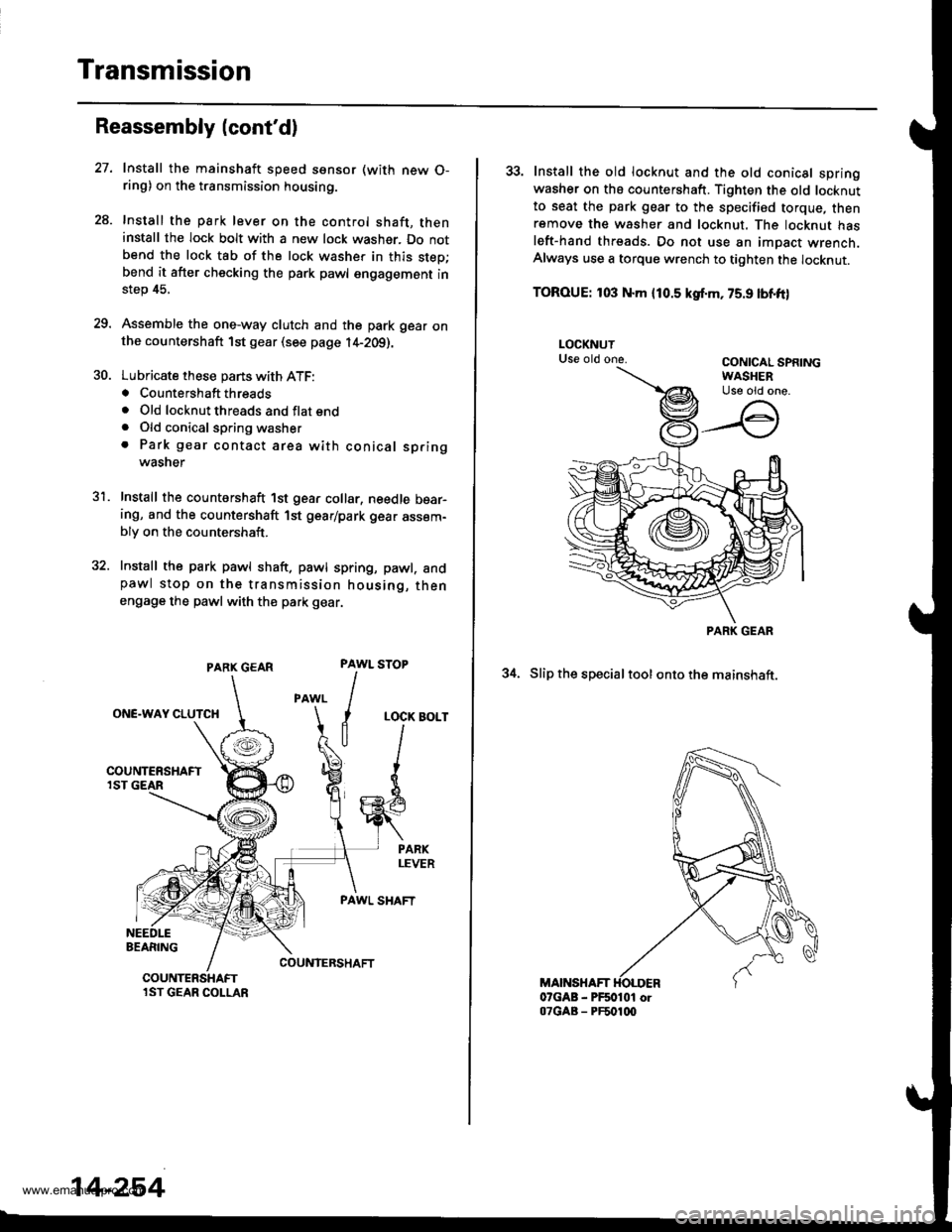
Install the mainshaft speed ssnsor (with new O-ring) on the transmission housing.
Install the park lever on the control shaft, theninstall the lock bolt with a new lock washer. Do notbend the lock tab of the lock washer in this step;bend it after checking the park pawl engagement instep 45.
Assemble the one-way clutch and the park gear onthe countershaft 1st gear (see page l4-2Og).
Lubricate these pans with ATF:. Countershaft threads. Old locknut threads and flat end. Old conical spring washer. Park gear contact area with conical springwasner
Install the countershaft 1st gear collar, needle bear-ing, and the countershaft 1st gear/park gear assem-bly on the countershaft.
Install the park pawl shaft. pawl spring, pawl. andpawl stop on the transmission housing, thenengage the pawl with th€ park gear.
31.
PAWL
I
I
a
STOP
LOCK BOLT
PAWL SHAFT
COUNIERSHAFTCOUNTERSHAFTlST GEAR COLLAR
14-254
33. Install the old locknut and the old conical springwasher on ths countershaft. Tighten the old locknutto seat the park gear to the specified torque, thenremove th€ washer and locknut. The locknut hasleft-hand threads. Do not use an impact wrench.Always use a torque wrench to tighten the locknut.
TOROUE: 103 N.m {10.5 kgf.m, 75.9 lbnft)
34. Slip the specialtool ontothe mainshaft.
MAINSHAFT07GAB - PF50101 or07GAB - PF501q)
PARK GEAR
www.emanualpro.com