end HONDA CR-V 1998 RD1-RD3 / 1.G Workshop Manual
[x] Cancel search | Manufacturer: HONDA, Model Year: 1998, Model line: CR-V, Model: HONDA CR-V 1998 RD1-RD3 / 1.GPages: 1395, PDF Size: 35.62 MB
Page 557 of 1395
TOROUE CONVERTER
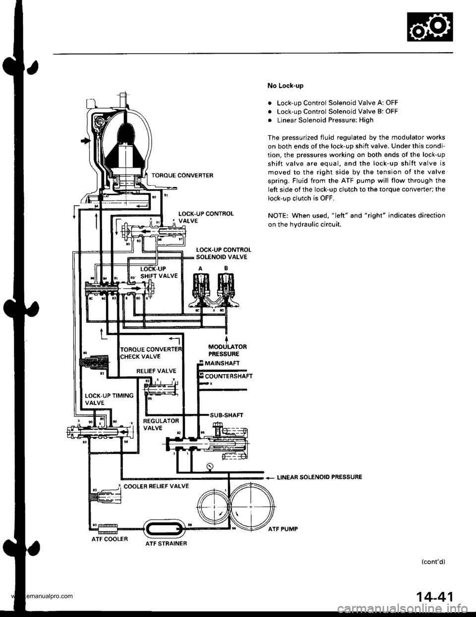
No Lock-up
. Lock-up Control Solenoid Valve A: OFF
. Lock-up Control Solenoid Valve B: OFF
. Linear Solenoid Pressure: High
The pressurized fluid regulated by the modulator works
on both ends of the lock-up shift valve. Under this condi-
tion, the pressures working on both ends of the lock-up
shift valve are equal. and the lock-up shift valve is
moved to the right side by the tension of the valve
spring. Fluid trom the ATF pump will flow through the
left side of the lock-up clutch to the torque converter; the
lock-up clutch is OFF.
NOTE: When us€d, "|eft" and "right" indicates direction
on the hydraulic circuit.
+ LINEAR SOLENOID PRESSURE
(cont'd)
LOCK.UP CONTROLSOI-ENOID VALVE
MOOULATORPRESSURE
MAINSHAFT
COUNTERSHAFTRELIEF VALVE
LOCK-UP TIMINGVALVE
i COOLER RELIEF VALVE
ATF STRAINERATF COOLER
ATF PUMP
14-41
www.emanualpro.com
Page 565 of 1395
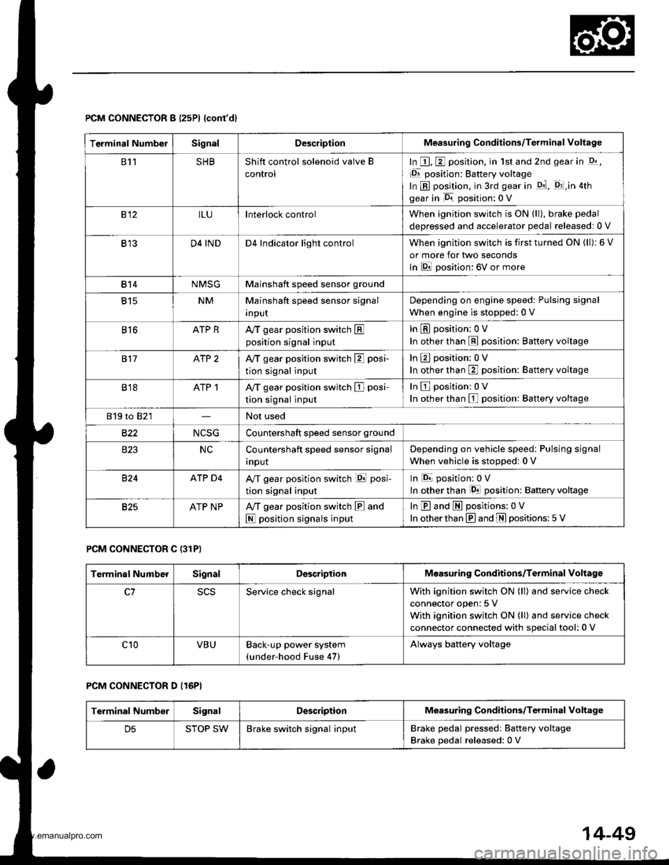
PCM CONNECTOR B (25P) lcont'd)
PCM CONNECTOR C {31PI
PCM CONNECTOR D II6PI
Terminal NumbelSignalDescriptionMeasuring Conditions/Terminal voltage
811SHBShift control solenoid valve B
control
In E, E position, in 1st and 2nd gear in -q,
Er position: Battery voltage
In B position, in 3rd gear in qd, q:l,in atn
gear in D. position: 0 V
812ILUlnterlock controlWhen ignition switch is ON (ll), brake pedal
deDressed and accelerator oedal released:0 V
B13D4 INDD4 Indicator light controlWhen ignition switch is first turned ON (ll): 6 V
or more for tlvo seconds
In lDll position: 6V or more
814NMSGMainshaft speed sensor ground
815NMMainshaft speed sensor signal
InpuI
Depending on engine speed: Pulsing signal
When engine is stopped: 0 V
816ATP RAy'T gear position switch Eposition signal input
In E position; OV
In other than E position: Battery voltage
817ATP 2Ay'T gear position switch E posi-
tion signal input
InEposition:0V
In other than E position: Battery voltage
B18ATP 1A/T gear position switch El posi-
tion signal input
InEposition:0V
In other than E position: Battery voltage
819 to 821Not used
B22NCSGCountershaft speed sensor ground
NCCountershaft speed sensor signal
Inpur
Depending on vehicle speed: Pulsing signal
when vehicle is stooped: 0 V
824ATP D4A/T gear position switch iql posi-
tion signal input
In E position: 0V
In other than lgal position: Baftery voltage
825ATP NPAy'T gear position switch E and
N position signals input
In E and E positions: 0V
In otherthan @ and ffi positions:5 V
Terminal NumberSignalDescriptionMeasuring Conditions/Terminal Voltage
SCSService check signalWith ignition switch ON (ll) and service check
connector open: 5 V
With ignition switch ON (ll) and service check
connector connected with special tool: 0 V
c10VBUBack-up power system(under-hood Fuse 47)
Always battery voltage
Terminal NumberSignalDescriptionMeasuring Conditions/Terminal Voltage
STOP SWBrake switch signal inputBrake pedal pressedr Battery voltage
Brake pedal released: 0 V
14-49
www.emanualpro.com
Page 571 of 1395
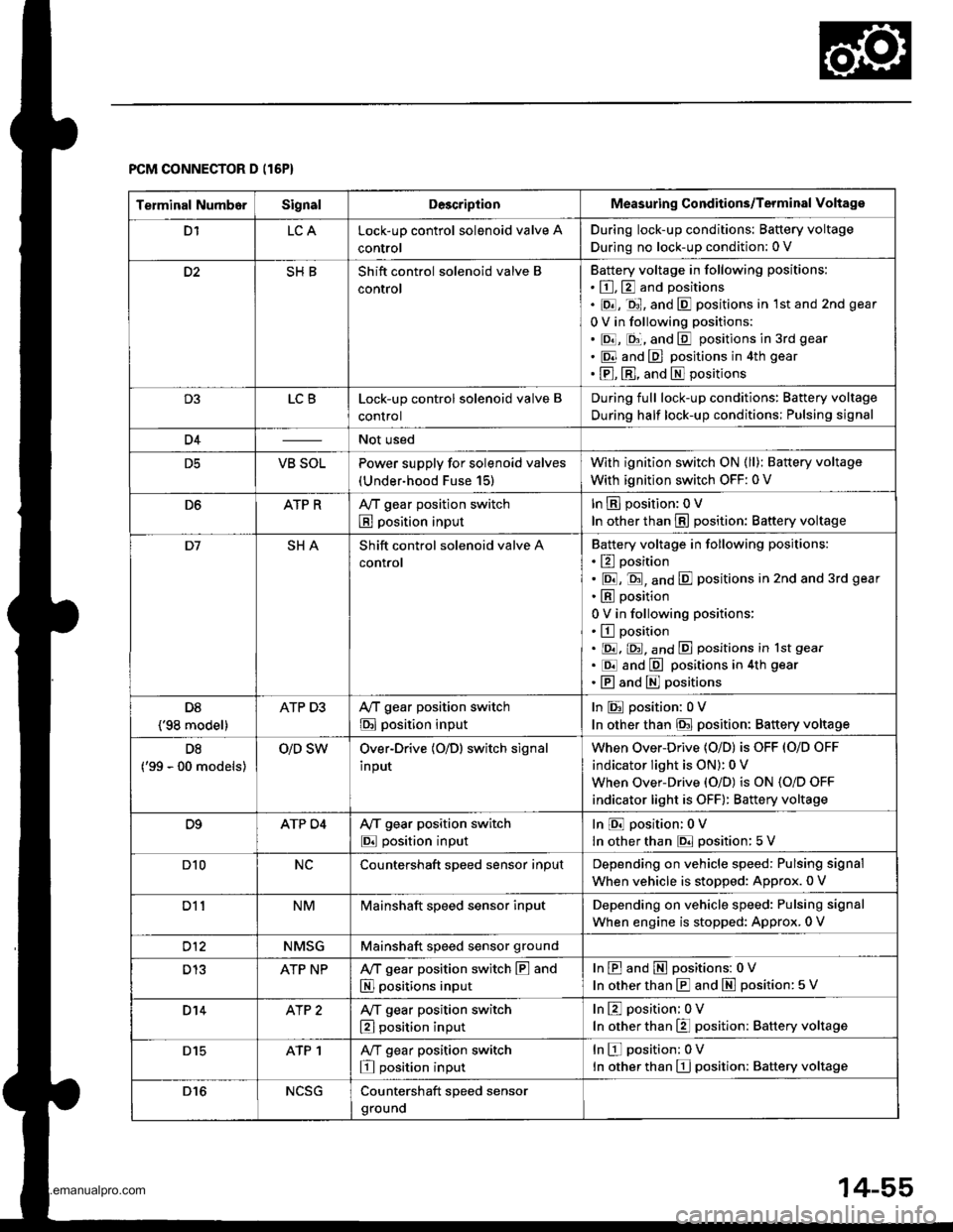
Terminal NumborSignalDescriptionMeasuring Conditions/Terminal Voltage
D1LCALock-up control solenoid valve A
control
During lock-up conditions: Baftery voltage
During no lock-up condition: 0 V
D2SHBShift control solenoid valve B
control
Battery voltage in following positions:
. E, E and positions
. E, -ql, and E positions in lst and 2nd gear
0 V in following positions:
. E, E;, and E positions in 3rd gear
. E and E positions in 4th gear
. E, El, and El positions
D3LCBLock-up control solenoid valve B
control
During full lock-up conditions: Battery voltage
During half lock-up conditions; Pulsing signal
D4Not used
D5VB SOLPower supply for solenoid valves
(Under-hood Fuse 15)
With ignition switch ON (ll); Battery voltage
With ignition switch OFF: 0 V
D6ATP RAy'T gear position switch
B position input
In E position: OV
In other than E position: Baftery voltage
D7SHAShift control solenoid valve A
control
Battery voltage in following positions:
. E position
. E, E, and E positions in 2nd and 3rd gear
. E position
0 V in following positions:
. E position. E. E, and E positions in lst gear
. Erl and E positions in 4th gear
.EandEpositions
D8
{'98 model}
ATP D3Ay'T gear position switch
E position input
In E position: 0V
In other than E position: Baftery voltage
D8
('99 - 00 models)
O/D SWOver-Drive (O/D) switch signal
input
When Over-Drive {O/D) is OFF (O/D OFF
indicator light is ON): 0 V
When Over-Drive {O/D) is ON {O/D OFF
indicator light is oFF): Battery voltage
D9ATP D4A/f gear position switch
E position input
In E position: 0V
In other than E position: 5 V
D10NCCountershaft sDeed sensor inoutDepending on vehicle speed: Pulsing signal
when vehicle is stopped: Approx.0 V
Dl1NMMainshaft speed sensor inputDepending on vehicle speed: Pulsing signal
When engine is stopped: Approx. 0 V
D12NMSGMainshaft speed sensor ground
D13ATP NPA,/T gear position switch E and
El positions input
InEandEpositions: 0V
In other than E and m position: 5 V
D14AlP 2A/T gear position switch
El position input
InE position; 0V
In other than E position: Battery voltage
D15ATP 1A,/T gear position switch
E position input
InEposition:0V
ln other than El position: Battery voltage
D16NCSGCountershaft speed sensor
grouno
PCM CONNECTOR D (16P)
14-55
www.emanualpro.com
Page 574 of 1395
Troubleshooting Procedures
(cont'dl
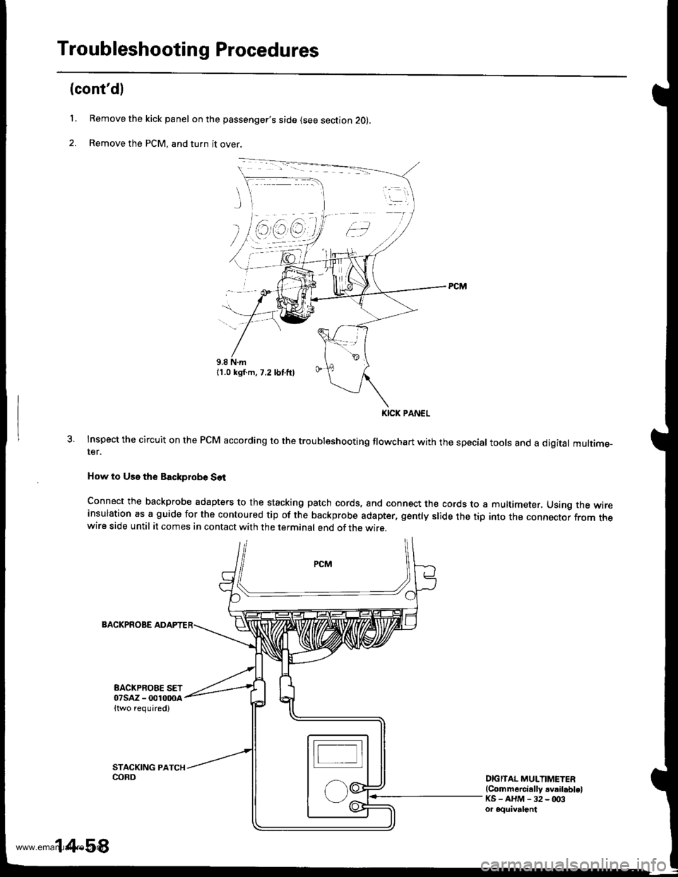
L Remove the kick panel on the passenger's side (see section 2O),
2. Remove the PCM, and turn it over.
Inspect the circuit on the PCM according to the troubleshooting flowchart with the special tools and a digital multime-ter.
How to Use the Backplobe Set
Connect the backprobe adapters to the stacking patch cords, and connect the cords to ainsulation as a guide for the contoured tip of the backprobe adapter, gently slide the tipwire side until it comes in contact with the terminal end of the wire.
multimeter. Using the wire
into the connector from the
BACKPROBE
EACKPROBE SET07sAz - 001000a{two required)
DIGITAL MULTIMETER(Commercially .v.ilablelKS-AHM-32-003ot oquivalont
KICK PANEL
14-58
www.emanualpro.com
Page 584 of 1395
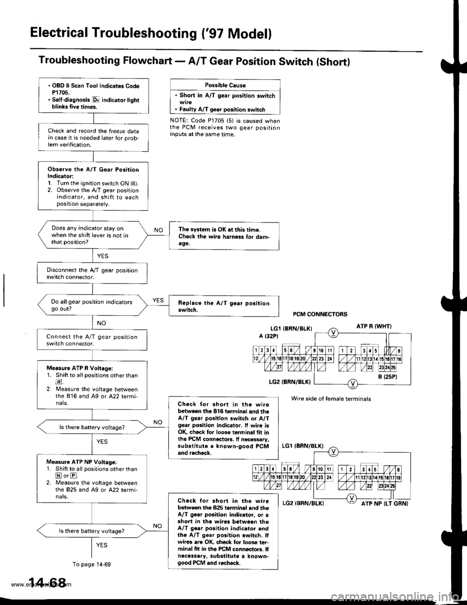
Electrical Troubleshooting {'97 Model}
Troubfeshooting Flowchart- AIT Gear Position Switch (Short)
Po$ible Cause
' Short in A/T gear position switch
. Faulty A/T gear position switch
NOTE: Code P1705 (5) is caused whenthe PCM receives two gear positionanputs at the same time.
. OBO ll Scan Tool indicat€s CodeP1705.' Selt-diagnosis p1- indicator tightblinb Iive times.
Check and record the freeze datain case it is needed later for prob-lem verification.
Observe the A/T G€ar Po3itionIndicator:1. Turn the ignition switch ON lll).2. Observe the A./T gear positionindicator, and shilt to eachposition separately.
Does any indicator stay onwhen the shift lever is not inthat position?
The system is OK .t this time.Ch6ck ihe wii6 harness for dam-490,
Do allgear position indicatorsgo out?
Measure ATP R Voltago:1. Shitt to all positions other thantr.2. lMeasure the voltage betweenthe 816 and Ag or A22 termi-nals.Check tor 3hort in the wirebetwaen the 816torminal and thoA/T gear pGilion switch or A/Tgsar posiiion indicator. ff wire isOK, check for 10036 torminal flt inlhe PICM connectoB. It necessary,substitute a known-9ood PCMand recheck.
Measure ATP NP Voltage:1. Shift to all positions other thanNorE.2. Measure the vohage betweenlhe 825 and Ag or A22 termi-nals.Chock for ahort in the wirebetw€en tho 825 torminal end theA/T 96.r pGition indicstor, or asho.t in tha wiro! b€tween theA/T gear po3ition indicator andthe A/T g€ar position lwitch. lfwircs ar€ OK, ch6ck for loos€ ter-minal fit in the PCM connectors. Itnece3sary, substitute a known-good PCM and recheck.
ls there battery vohage?
PCM CONNECTORS
Wire side of female terminals
ATP NP {LT GRNI
14-68
To page 14-69
www.emanualpro.com
Page 585 of 1395
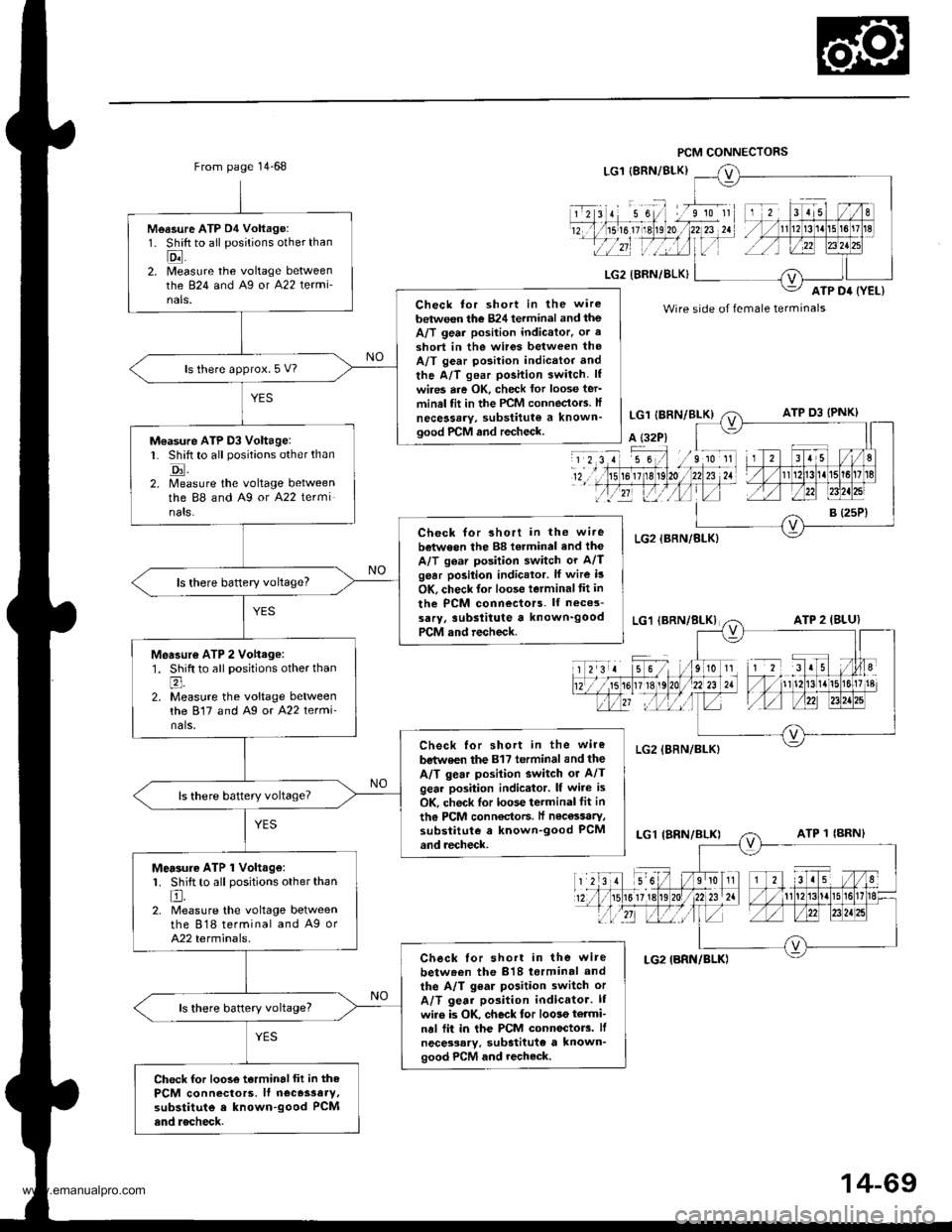
From page 14-68
Measure ATP D4 Voltage:1. Shift to all positions other than
Eil2. [/leasure the voltage betweenthe 824 and Ag or A22 termi-nals.Check tor short in the wire
between the 824 terminal and theA/T geai position indicator. or a
3hort in the wir6s between theA/T gear position indicttor and
the A/T gear position switch. lf
wires are OK, check lor loose ter'minal fit in the PCM conneclo.s. lf
necessary, substitute a known'good PrCM and recheck.
ls there approx. 5 V?
M€asure ATP D3 Voltage:L Shift to all positions other than
tr.2. Measure the voltage betweenthe 88 and A9 or A22 terminats.
Check for short in the wi.ebetween the 88 torminal and the
A/T gear position switch or A/Tgear position indicator. lf wire i3
OK, check lor loose terminaltit in
the PCM connectors. lf neces-
sarY, 3ubslitute a known'goodPCM and recheck.
ls there baftery voltage?
Measur€ ATP 2 Vohage:1. Shift to all positions other thanl;
2. Measure the voltage betweenthe 817 and Ag or A22 termi'nals.
Check for short in the wire
bstwe€n the 817 terminal and the
A/T gear posilion switch or A/Tgear position indicator. lf wire is
OK, check lor loose terminal fit in
th6 PCM conn€ctoF. lf nec€ssaty,substitute a known-good PCMand recheck.
Mersure ATP 1 Volt.ge:1. Shift to all positions other than
El.2. Measure the voltage betweenthe 818 terminal and A9 orA22 terminals.
Check lor short in the wire
betw.en the 818 torminal and
the A/T gear position switch or
A/T gear position indicator. lI
wiro is OK. check for loose termi-nal fii in the PCM connectorc. lf
necessary. substitute a known'good PCM and recheck.
ls there battery voltage?
Check for loose terminalfit in thePCM connectors, lf neces3aty,substitute e known-good PCMend rocheck.
Wire side of female terminals
14-69
www.emanualpro.com
Page 596 of 1395
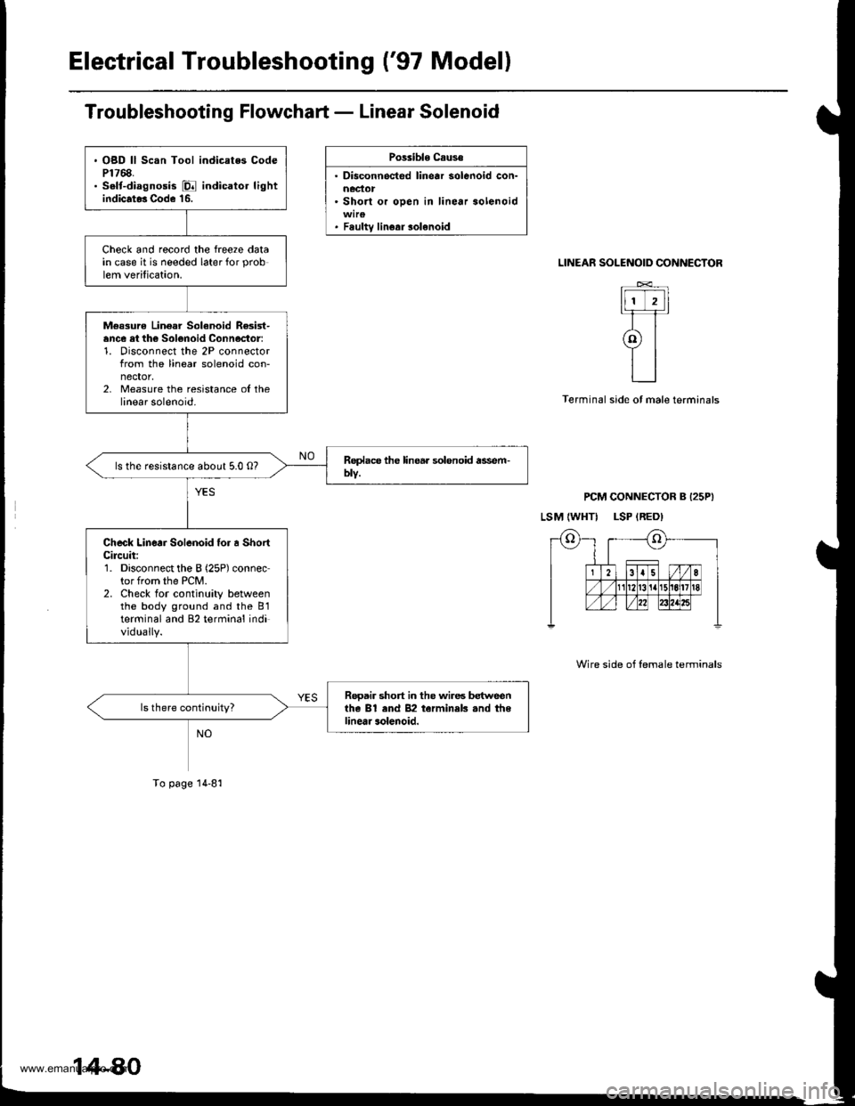
Electrical Troubleshooting ('97 Modell
Troubleshooting Flowchart - Linear Solenoid
Possible Caus€
. Disconnocted linear solenoid con-
. Short or oDen in linear solenoid
. Fsultv linear solenoid
SOLENOID CONNECTOR
t-TTIt]]lt
tl I ? rl-Tr
atll
L_l
PCM CONNECTOR B I25PI
LSM {WHTI LSP {RED)
LINEAR
Terminal side ot male terminals
Wire side of lemale terminals
. OBD ll Scan Tool indicates CodeP1768.. S.lt-diagnosis E indicator lightindicat* Code 16.
Check and record the freeze datain case it is needed later for prob
lem verification.
M€ssurc Linear Solanoid Re3ist-ance ei th€ Solonoid Connoctor:1. Disconnect the 2P connectorfrom the linear solenoid con-nector,2, Measure the resistance ol thelinear solenoid.
ls the resistance about 5.0 O?
Check Linear Solenoid {or a ShortCileuit:1. Disconnect the B (25P) connector from the PCM.2. Check for continuity betweenthe body ground and the B1terminal and 82 terminal individually.
Rooair short in the wires betweenthe Bl end 82 terminek .nd thelinear solenoid.
To page 14-81
www.emanualpro.com
Page 620 of 1395
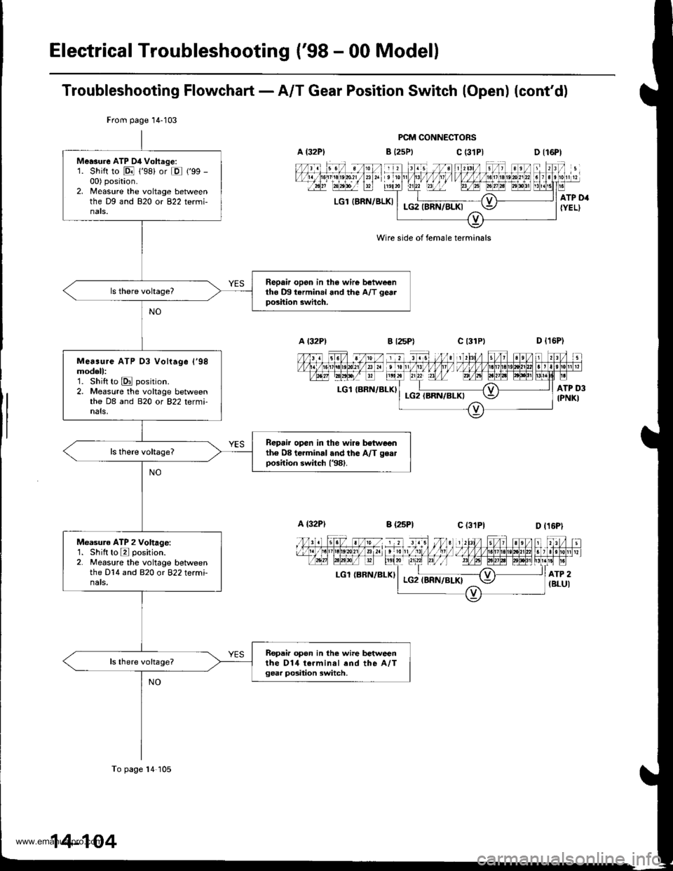
Electrical Troubleshooting ('98 - 00 Model)
Troubleshooting Flowchart - A/T Gear Position Switch (Open) (cont'd)
PCM CONNECTORS
B {25Ptc (31P|
LGl IERN/BLKI
Wire side of female terminals
LGl {BRN/BLKI
LGl {BRN/ELXI
From page 14-103
Me.sure ATP D4 Vohrge:1. Shift to E 1'98) or E ('99 -
00) position.2. Measure the voltage betweenthe Dg and 820 or 822 termi-nats.
Repair opon in th6 wire betweentho m tarminal and the A/T gealposition swhch.
Me..ure ATP 03 Vohage l'98modell:1. Shift to E position.2. Measure the voltage betweenthe DB and 820 or 822 tetmi-nals,
Repair open in the wire botwoonth6 08 terminal .nd the A/T geatposition switch (381.
Measuro ATP 2 Voltage:1. Shilt to E position.2. Measure the voltage betweenthe D14 and 820 or 822 terminats.
Repair opon in the wire betweenthe D14 t€.minal end the A,/Tgear po3ition switch,
To page 14 105
www.emanualpro.com
Page 654 of 1395
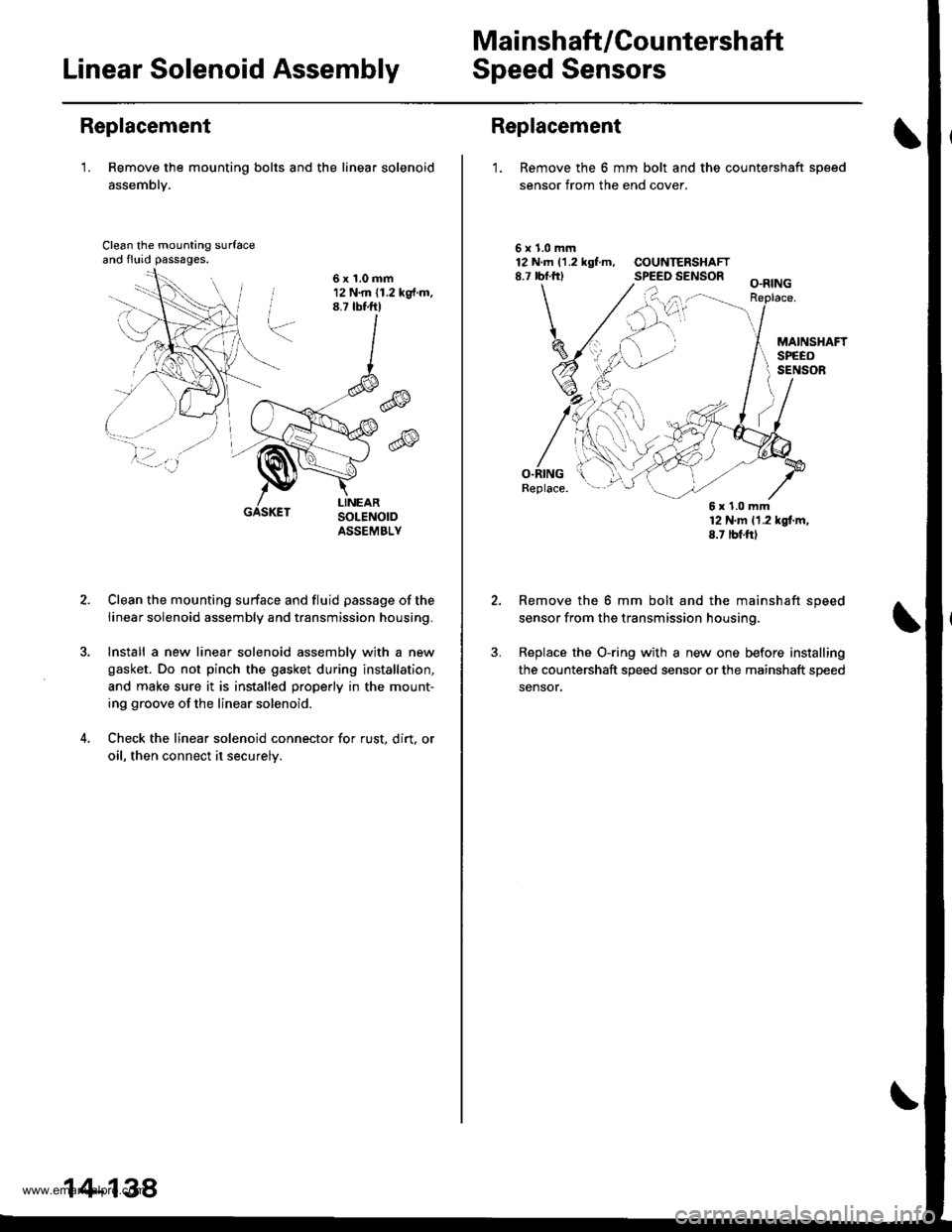
Mai nshaft /Cou ntershaft
Linear Solenoid AssemblySpeed Sensors
Replacement
'1. Remove the mounting bolts and the linear solenoid
assemblY.
Clean the mounting surfaceand fluid passages.
6x1.0mm12 N.m (1.2 kg{.m.8.7 tbtftl
@
@
GASKET
Clean the mounting surface and fluid passage of the
linear solenoid assembly and transmission housing.
Install a new linear solenoid assemblv with a new
gasket. Do not pinch the gasket during installation,
and make sure it is installed properly in the mount-
ing groove of the linear solenoid.
Check the linear solenoid connector for rust. dirt, or
oil, then connect it securelv.
14-138
Replacement
1. Remove the 6 mm bolt and the countershaft sDeed
sensor from the end cover.
\
5x1.0mm12 N.m 11.2 kgf.m, COUNTERSHAFT8.7 rbf.frl SPEED SENSOR
O.RINGReplace.
12 N'm 11.2 kgl.m,8.7 tbf.ftl
Remove the 6 mm bolt and the mainshaft speed
sensor from the transmission housing.
Replace the O-ring with a new one before installing
the countershaft speed sensor or the mainshaft speed
sensor,
6x1.0mm
www.emanualpro.com
Page 656 of 1395
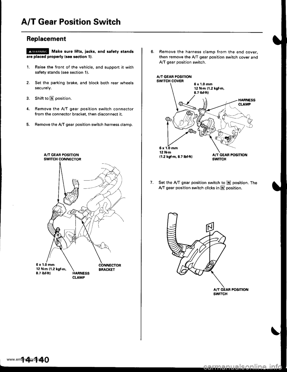
A/T Gear Position Switch
Replacement
@ Make 3ure lifts, iacks, and safety stands
ar€ placod properly lsoo soction 1).
1. Raise the front of the vehicle, and support it with
safety stands (see section 1).
2. Set the parking brake, and block both rear wheels
securely.
3. Shift to E position.
Remove the A/T gear position switch connector
from the connector bracket, then disconnect it.
Remove the AfI gear position switch harness clamp.
5x1.0mm12Nm11.2kgf.m,8.7 tbf.fttBRACIGT
14-140
6. Remove the harness clamp from the end cover,
then remove the Aff gear position switch cover and
Ay'T gear position switch.
A/T GEAF POSITIONswrTcH covER6x1.0mm12 N.m 11.2 kgt m.8.7 lbf.ftl
1.Set the IVT gear position switch to E position. The
AfI gear position switch clicks in E position.
POSmON
6x1.0mm12 N.m
{1.2 kg{.m,8.7 lbtftl
swlTcH
www.emanualpro.com