Back HONDA CR-V 1998 RD1-RD3 / 1.G Workshop Manual
[x] Cancel search | Manufacturer: HONDA, Model Year: 1998, Model line: CR-V, Model: HONDA CR-V 1998 RD1-RD3 / 1.GPages: 1395, PDF Size: 35.62 MB
Page 981 of 1395
Pulsers/Wheel Sensors
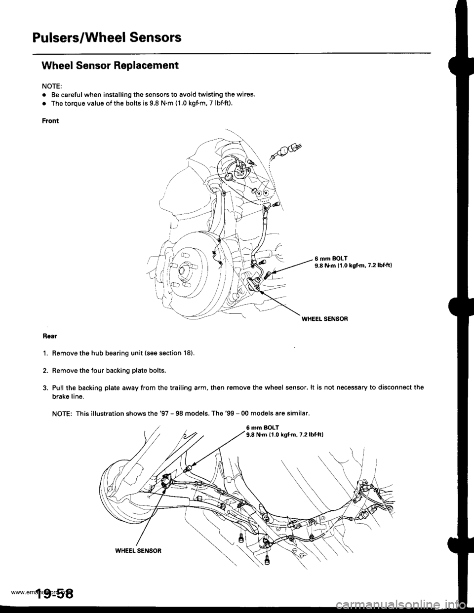
Wheel Sensor Replacement
NOTE;
. Be carefulwhen installing the sensors to avoid twisting the wires.
. The torque value of the bolts is 9.8 N.m ( 1.0 kgf.m, 7 Ibf.ft).
Front
6 mm BOLT9.8 N.m {1.0 kgtm. ?.2lbf'ft)
WHEEL SENSOR
Rgar
1. Remove the hub bearing unit (see section 18).
2. Remove the tour backing plate bolts.
3, Pull the backing plate away from the trailing arm, then remove the wheel sensor. lt is not necessary to disconnect the
brake line.
NOTE: This illustration shows the '97 - 98 models, The '99 - 00 models are similar.
6 mm BOLT9,8 N.m 11.0 kgf.m, 7.2lbf.ft)
\all
19-58
WHEEL SENSOR
www.emanualpro.com
Page 1003 of 1395
Doors
Front and Rear Door Glass
Adiustment (cont'dl
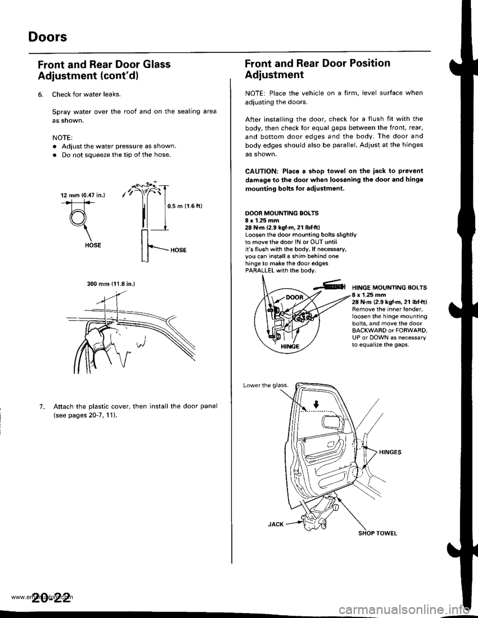
6. Check for water leaks.
Spray water over the roof and on the sealing area
as snown.
NOTE:
. Adjust the water pressure as shown.
. Do not soueeze the tio of the hose.
12 mm {0.47 in.l
#
(r\"1
HOSE
-"'*r"i
,'r)"f
tl
0.5 m (1.6 ftl
7. Attach the plastic cover, then install the door panel
(see pages 20-7, 'l 1),
20-22
..-
300 mm 111.8 in.)
Front and Rear Door Position
Adjustment
NOTE: Place the vehicle on a firm, level surface when
adiusting the doors.
After instailing the door, check for a flush fit with the
body, then check lor equal gaps between the front, rear.
and bottom door edges and the body. The door and
body edges should also be parallel. Adjust at the hinges
as shown.
CAUTION: Placa a shop towel on the iack to prevent
damage to the door when loosening the door and hinge
mounting bolts lor adiustment.
DOOR MOUNTING BOLTSI x 1.25 mm28 N.m 12.9 kgtr.m, 21 lbI.ftlLoosen the door mounting bolrs slighrlyto movethe door lN or OUT untilit's flush with the bodv. lf necessary,you can installa shim behind onehinge to make the door edgesPARALLEL with the bodv.
HINGE MOUNTING BOLTS8 x 1.25 mm28 N,m 12.9 kgt.m. 21 lbl.ftlRemove the inner fender,loosen the hinge mountingbolts, and move the doorBACKWARD or FORWARD,UP or DOWN as necessaryto equalize the gaps.
Lower the glass.
www.emanualpro.com
Page 1011 of 1395
Glass
Windshield Replacement
CAUTION:
. Put on gloves to protect your hands.
. Use seat covers to avoid damaging any surfaces.
1. To remove the windshield, first remove the:
. Rearview mirror (see page 20-28)
. Sunvisors and holders (see page 20-44l'
. Ceiling light (see section 23)
. Grab handle (see page 20-44)
. Front door trim (see page 20-41)
. Front pillar trim (see page 20-41)
. Windshield wiper arms and cowl cover (see page
20-98)
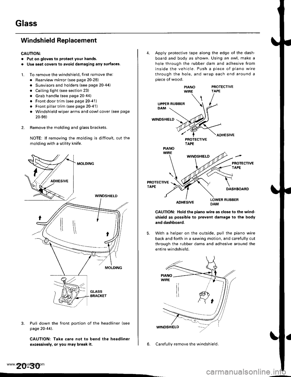
2. Remove the molding and glass brackets.
NOTE: lf removing the molding is difficult, cut the
moldlng with a utility knife.
MOLDING
3. Pull down the front Dortion of the headliner (see
page 20-44).
CAUTION: Take care not to bend the headliner
excessivsly, or you may break it.
WINDSHIELD
20-30
4. Apply protective tape along the edge ot the dash-
board and body as shown. Using an awl, make a
hole through the rubber dam and adhesive from
inside the vehicle. Push a piece of piano wire
through the hole, and wrap each end around a
piece of wood.
PROTECTIVETAPE
WINDSHIELD
ADHESIVE
PIANOWIRE
PROTECTIVETAPE
WINDSHIELO
PROTECTIVETAPEDASHBOARD
ADHESIVELOWER RUBBERDAM
CAUTION: Hold the piano wire as close to the wind-
shield as possible to prevent damage to the body
and dashboard.
5. With a helper on the outside, pull the piano wire
back and fo(h in a sawing motion, and carefully cut
through the rubber dams and adhesive around the
entire windshield.
6. Carefully remove the windshield.
UPPER RUBBER
PIANO
www.emanualpro.com
Page 1027 of 1395
![HONDA CR-V 1998 RD1-RD3 / 1.G Workshop Manual
lnterior Trim
5.
Carpet Replacement (contdl
Remove the center lower cover (M/T model).
>: Clip locations,2
lN
-ffi]
6. Remove the SRS unit covers.
>: Clip locations,2
.dL ItEu( |- qf I cARPET
FASTE HONDA CR-V 1998 RD1-RD3 / 1.G Workshop Manual
lnterior Trim
5.
Carpet Replacement (contdl
Remove the center lower cover (M/T model).
>: Clip locations,2
lN
-ffi]
6. Remove the SRS unit covers.
>: Clip locations,2
.dL ItEu( |- qf I cARPET
FASTE](/img/13/5778/w960_5778-1026.png)
lnterior Trim
5.
Carpet Replacement (cont'dl
Remove the center lower cover (M/T model).
>: Clip locations,2
lN'
-ffi]
6. Remove the SRS unit covers.
>: Clip locations,2
.dL ItEu( |- qf I cARPET
FASTENER('98 - 00 models)SNS UNIT
7. '97 model: Cut areas @ and @ in the carpet, then
pullthe carpet back.'98 - 00 models: Release the fastener and cut area
@ in the carpet, then pull the carpet back.
COVER
COVER
20-46
8. Remove the clips, and release the fasteners. then
remove the carpet.
NOTE: Take care not to damage, wrinkle or twist the
carpet.
>: Clip locations.3
FASTENER
lnstallation is the reverse of the removal procedure.
NOTE:
. Take care not to damage. wrinkle or twist the
carper.
. Make sure the seat harness is routed correctly.
. lf necessary, replace any damaged clips.
. Reaftach the cut areas @ and @ ('97 model) or
cut area @ ('98 - OO models) in the carpet with
wire ties.
www.emanualpro.com
Page 1040 of 1395
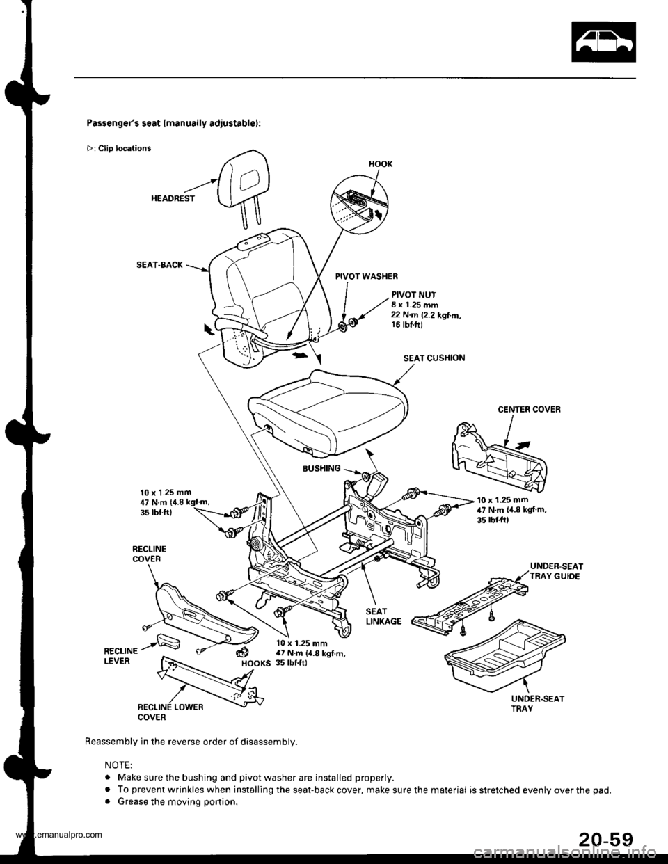
Passenger's seat (manually adiustablel:
>: Clip locations
HEADREST
SEAT.BACK
10 x 1.25 mm
PIVOT WASHER
PIVOT NUT8 x 1.25 mm22 N.m 12.2 kgl..n,16 tbt.ftl
SEAT CUSHION
CENTER COVER
BUSHING
COVER
Reassembly in the reverse order of disassembly.
NOTE:
. Make sure the bushing and pivot washer are installed properly.
. To prevent wrinkles when installing the seat-back cover, make sure the. Grease the moving portion.
'10 x 1.25 mm47 N.m {4.8 kgf m,
35 rbl.ft)
UNDER-SEATTRAY GUIDE
,U N.m 14.835 rbt.ft)
dHOOKS
10 x 1.25 mm17 N.m {4.8 kgl.m,35 tbf.ft)
HOOK
material is stretched evenly over the pad.
www.emanualpro.com
Page 1042 of 1395
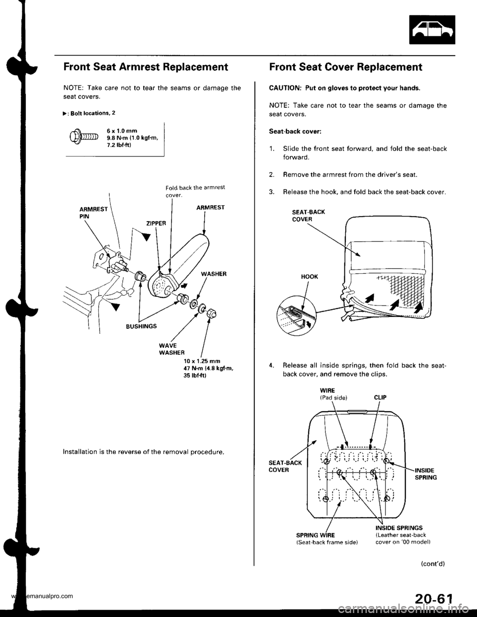
Front Seat Armrest Replacement
NOTE: Take care not to tear the seams or damage the
seat coverS.
>: Bolt locations.2
6r1.0mm9.8 N,m ll.0 kgl.m,7,2 tbf.ft)
10 x 1.25 mm47 N.m 1,1.8 kgf,m,35 tbt{t)
Installation is the reverse of the removal procedure.
Front Seat Cover Replacement
CAUTION: Put on gloves to protect your hands.
NOTE: Take care not to tear the seams or damage the
seat covers.
Seat-back cover:
'1. Slide the front seat forward, and fold the seat-back
forward.
2.
3.
Remove the armrest from the driver's seat.
Release the hook, and fold back the seat-back cover.
4.Release all inside springs, then fold back the seat-
back cover. and remove the clios.
WIRE{Pad sidei
(Seat back frame sjde) cover on '00 model)
(cont'd)
20-61
SEAT-BACK
www.emanualpro.com
Page 1043 of 1395
Seats
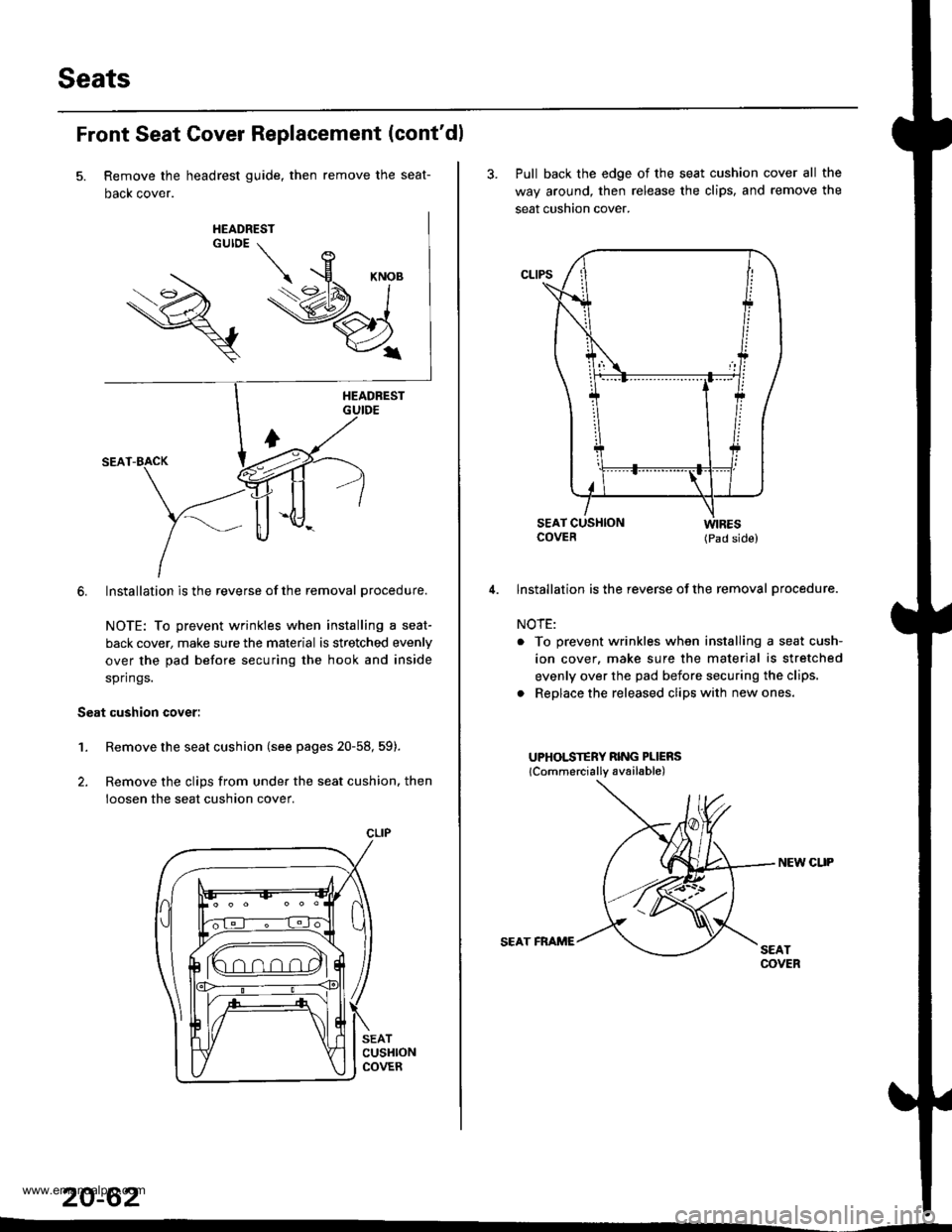
Front Seat Cover Replacement (cont'dl
Remove the headrest guide, then remove the seat-
Dacx cover.
6. Installation is the reverse of the removal procedure.
NOTE: To prevent wrinkles when installing a seat-
back cover, make sure the material is stretched evenly
over the pad before securing the hook and inside
springs.
Seat cushion cover:
1.Remove the seat cushion (see pages 20-58, 59).
Remove the clips from under the seat cushion. then
loosen the seat cushion cover.
SEATCUSHIONCOVER
20-62
CLIP
3. Pull back the edge of the seat cushion cover all the
way around, then release the clips. and remove the
seat cushion cover.
COVER (pad side)
lnstallation is the reverse of the removal procedure.
NOTE:
. To prevent wrinkles when installing a seat cush-
ion cover. make sure the material is stretched
evenly over the pad before securing the clips.
. Replace the released clips with new ones.
UPHOLSTERY RING PLIERS
lCommercially available)
NEW CUP
SEAT FRAME
www.emanualpro.com
Page 1046 of 1395
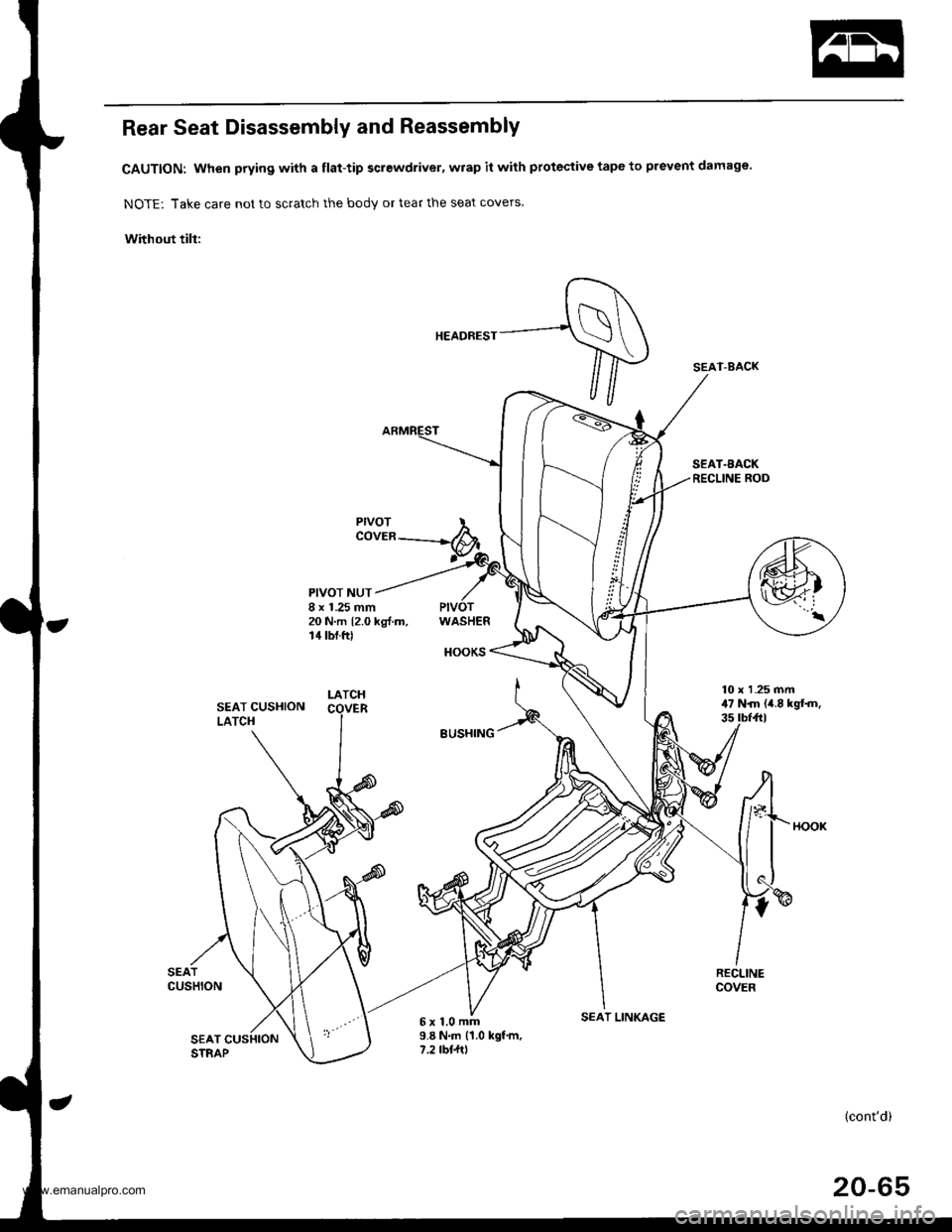
Rear Seat Disassembly and Reassembly
CAUTION: When prying with a flat-tip screwdriver, wrap it with protective tape to prevent damage.
NOTE: Take care not to scratch the body or tear the seat covers.
Without till:
SEAT.AACKRECLINE ROD
PIVOTCOVER
PIVOT NUT8 x 1.25 mm20 N.m 12.0 kg{.m.14 tbf.ftlWASHER
HOOKS
5x1.0mm9.8 N'm (1.0 kgf.m,7 .2 tbl.ltl
(cont'd)
20-65
SEAT-BACK
SEAT CUSHIONLATCH
SEATCUSHION
SEAT CUSHIONSTRAP
SEAT LINKAGE
www.emanualpro.com
Page 1047 of 1395
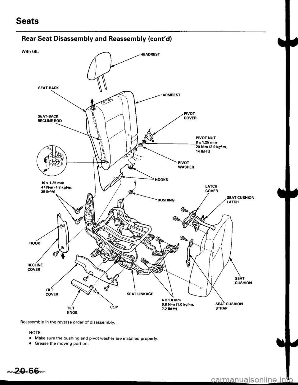
Seats
Rear Seat Disassembly and Reassembly (cont'd)
with tilr:
SEAT.BACKRECLINE ROO
10 x 1.25 mm47 N.m {4.8 kgfn,35 tbtft)
PIVOT NUTx 1.25 mm20 N{n (2.0 kgt.m,14 tbt-fr)
I-ATCHCOVER
SEAT CUSHIONLATCH
SEATCUSHION
SEAT LINKAGE
T;LT CLIP
KNOB
Reassemble in the reverse order of disassembly.
NOTE:
. Make sure the bushing and pivot washer are installed properly.. Grease the moving portion.
6x1.0mm9.8 N.m {1.0 kgf.m,7.2 tbf.ftl
SEAT CUSHIONSTRAP
20-66
SEAT-BACK
www.emanualpro.com
Page 1050 of 1395
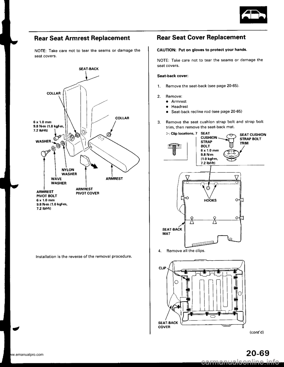
Rear Seat Armrest Replacement
NOTE: Take care not to tear the seams or damage the
seat covers.
COLLAR
COLLAR6x1.0mm9.8 N.m {1.0 kgf.m,7.2 rbr.ft)
WASHER
NYLONWASHER
VEARMRESTWASHER
ARMRESTPIVOT BOLT6x1.0mm9.8 N.m (1.0 kgt.m,7.2lbllll
lnstallation is the reverse of the removal procedure.
SEAT.BACK
Rear Seat Cover Replacement
CAUTION: Put on gloves to protect your hands.
NOTE: Take care not to tear the seams or damage the
seal covers.
Seal-back cover:
Remove the seat-back {see page 20-65).
Remove:
a Armrest
. Headrest
. Seat-back recline rod (see page 20-65)
Remove the seat cushion strap bolt and strap bolt
trim, then remove the seat-back mat.
L
2.
"'---.' t.-r" t-- i,': "" '
4. Remove all the clips.
(cont'd)
20-69
www.emanualpro.com