Back HONDA CR-V 1998 RD1-RD3 / 1.G Workshop Manual
[x] Cancel search | Manufacturer: HONDA, Model Year: 1998, Model line: CR-V, Model: HONDA CR-V 1998 RD1-RD3 / 1.GPages: 1395, PDF Size: 35.62 MB
Page 1051 of 1395
Seats
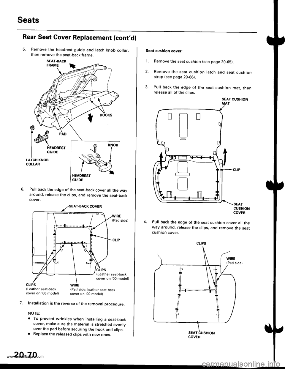
Rear Seat Cover Replacement (cont'dl
Remove the headrest guide and latch knob collar,then remove the seat-back frame.
SEAT.BACKFRAME i
Pull back the edge of the seat-back cover all the wayaround. release the clips, and remove the seat-backcover.
€ --t)c/
l@
pio
I HEADREST
I GUroE
LATCH KNOBCOLLAR
CLIPS(Leather seat-backWIRE(Pad side, leather seat,back
1.
20-70
cover on '00 model) cover on ,00 model)
Installation is the reverse of the removal procedure.
NOTE:
o To prevent wrinkles when installing a seat_backcover, make sure the material is stretched evenlyover the pad before securing the hook and clips.. Replace the released clips with new ones.
Soat cushion cover:
'1. Remove the seat cushion (see page 20-65).
2. Remove the seat cushion
strap (see page 20-66).
3. Pull back the edge of the
release all of the clips.
latch and seat cushion
seat cushion mat, then
SEAT CUSHIONMAT
CUSHIONCOVER
Pull back the edge of the seat cushion cover all theway around, release the clips, and remove the seatcushton cover.
t-t
tl
L]
CLIPS
COVER
www.emanualpro.com
Page 1062 of 1395
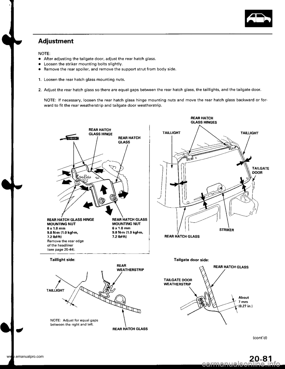
Adjustment
NOTE:
. After adjusting the tailgate door, adjust the rear hatch glass.
. Loosen the striker mounting bolts slightly.
. Remove the rear spoiler, and remove the support strut from body side.
1. Loosen the rear hatch glass mounting nuts.
2. Adjust the rear hatch glass so there are equal gaps between the rear hatch glass, the taillights, and the tailgate door.
NOTE: lf necessary, loosen the rear hatch glass hinge mounting nuts and move the rear hatch glass backward or for-
ward to fit the rear weatherstrip and tailgate door weatherstrip.
REAR HATCI{GLASS HINGES
REAR HATCH GLASS HINGEMOUNTING NUT6x1.0mm9.8 N.m (1.0 kgf.m,7.2 tbt f Remove the rear edgeotthe headliner(see page 20-44).
MOUNTING NUT6x1.0mm9.8 N.m 11.0 kgtm,7.2 rbf.ftt
Taillight side:Tailgate door side:
About7mm
1o.27 in.l
NOTE: Adjust for equal gapsbetween the right and left.TCH GLASSIHAREAR
(cont'd)
20-81
www.emanualpro.com
Page 1075 of 1395
Openers
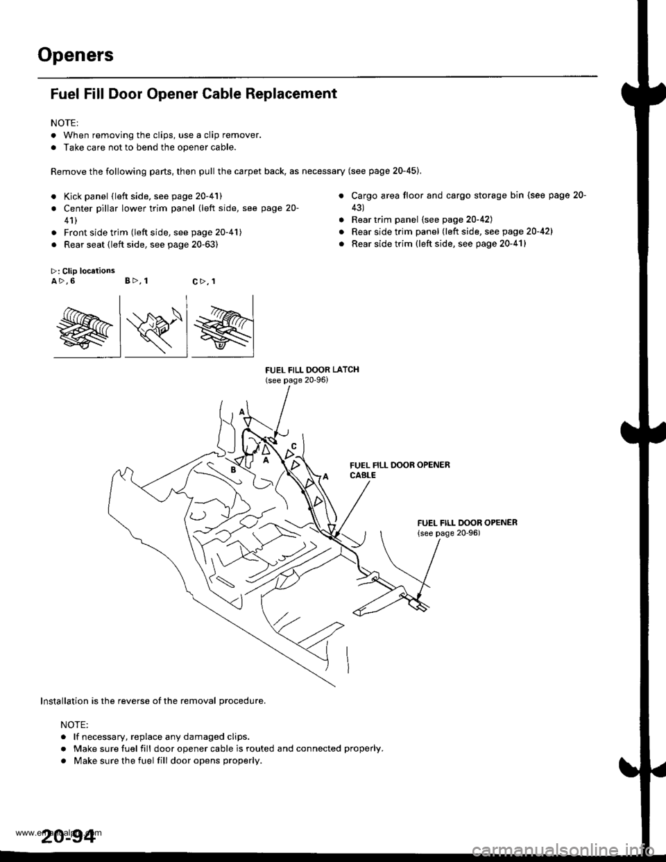
Fuel Fill Door Opener Cable Replacement
NOTE:
. When removing the clips, use a clip remover.
. Take care not to bend the opener cable.
Remove the following parts, then pull the carpet back, as necessary (see page 20-45),
a
>: Clip locationsA>,6 B>, 1
a
a
FUEL FILL OOOR LATCH(see page 20-96)
Kick panel (left side. see page 20-41)
Center pillar lower trim panel (left side, see page 20-
41)
Front side trim (left side, see page 20-41)
Rear seat (left side, see page 20-63)
Cargo area floor and cargo storage bin (see page
43)
Rear trim panel {see page 20-42)
Rear side trim panel (left side, see page 20-421
Rear side trim (left side, see page 20-41)
FUEL FILL DOOR OPENER
{see page 20-96)
20-
c>,1
@lRlg
Installation is the reverse of the removal procedure.
NOTE:
. lf necessary, replace any damaged clips.
r Make sure fuel fill door opener cable is routed and connected properly.
. Make sure the fuel fill dooropens properly.
www.emanualpro.com
Page 1082 of 1395
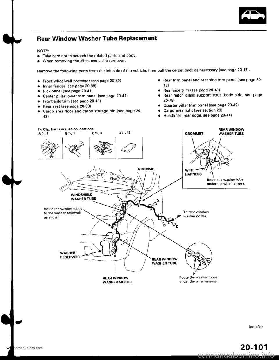
Rear Window Washer Tube Replacement
NOTE:
. Take care not to scratch the related parts and body.
. When removing the clips, use a clip remover.
Remove the following parts from the left side of the vehicle, then
. Front wheelwell protector (see page 20-89)
. Innertender (see page 20-89)
. Kick panel (see page 20-4't)
. Center pillar lower trim panel (see page 20-41)
. Front side trim (see page 20-41)
. Rear seat (see page 20-63)
a Cargo area floor and cargo storage bin (see page 20-
43)
>: Clip, harness cu3hion location3c>,3D>,12A>, 1B>, 1
Route the washer t!be
under the wire harness
Route the washer tubesto the washer reservoir
WASHEBRESERVOIR
wasner no2zre.
@s_l el 4
WINDSHIELDWASHEB TUBE
REAR WINDOWWASHER MOTOR
GROMMET
wrNoowWASHER TUBE
pull the carpet back as necessary (see page 20-45)
. Rear trim panel and rear side trim panel (see page 20-
42J
. Rear side trim (see page 20-41)
. Rear hatch glass support strut (body side, see page
20-7Al
. Ouarter pillartrim panel (see page 20-421
o Cargo area light (see section 23)
. Headliner (rear edge, see page 20-44)
GROMMET
(cont'd)
20-101
www.emanualpro.com
Page 1092 of 1395
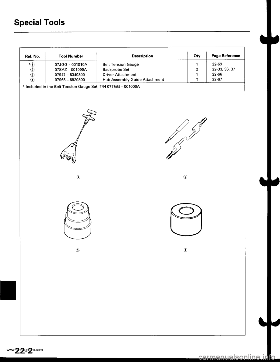
Special Tools
Rel. No. I Tool NumberDescriptionOty I Page Relerence
.o
6,
@
@
07JGG - 001010A
07sAz - 001000A
07947 - 6340300
07965 - 6920500
Belt Tension Gauge
Backprobe Set
Driver Attachment
Hub Assembly Guide Attachment
1
2
1
1
22-69
22-33,36,37
22-66
22-61
* Included in the Belt Tension Gauge Set, T/N 07TGG - 001000A
t
o
22-2
www.emanualpro.com
Page 1123 of 1395
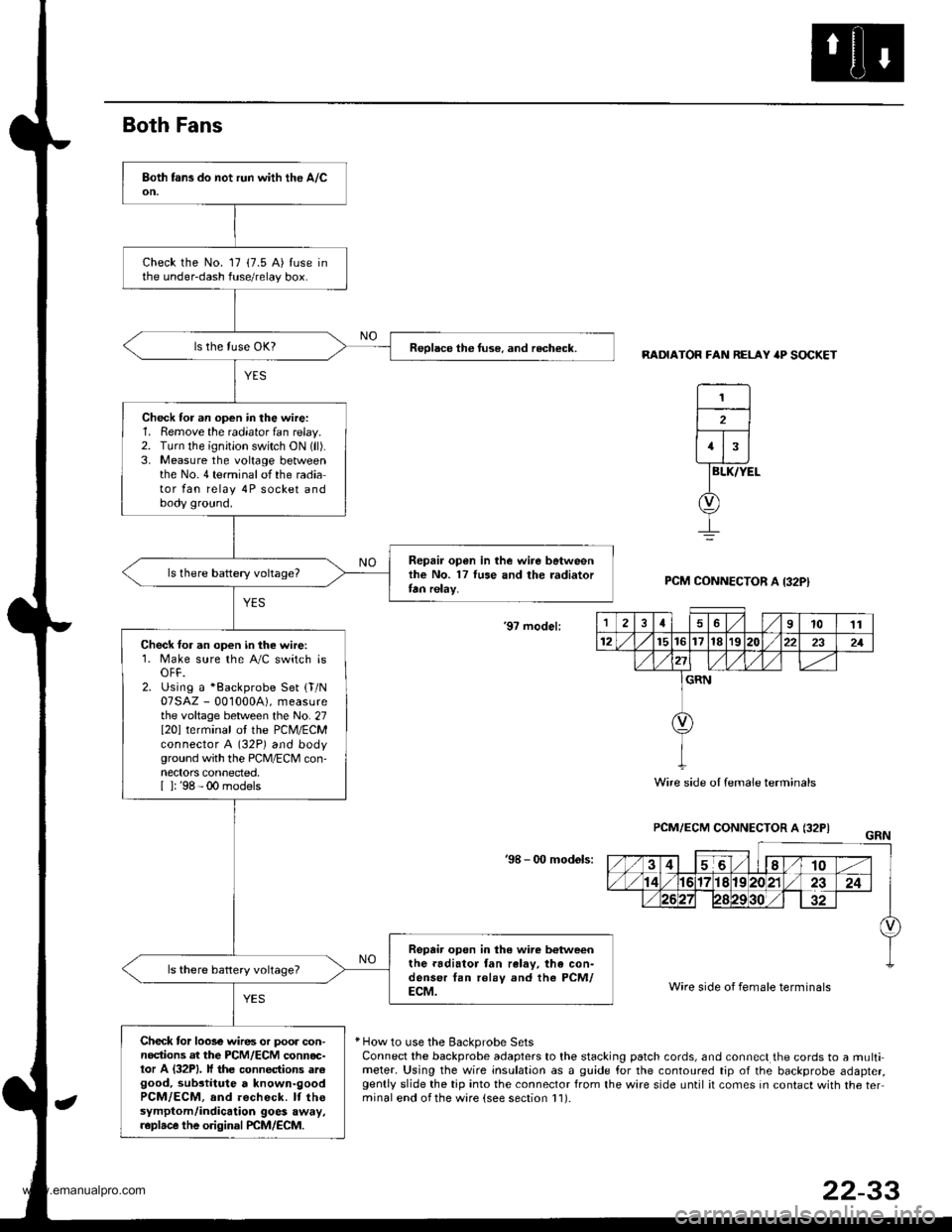
Both Fans
RADIATOR FAN RELAY 'P SOCKET
BLK/YEL
PCM CONNECTOR A I32PI
'9? model:
PCM/ECM CONNECTOR A (32PI
'98 - 0O mod6ls:
Wire side of female terminals
* How to use the Backprobe SetsConnect the backprobe adapters to the stacking patch cords, and connect the cords to a multimeter. Using the wire insulation as a guide for the contoured tip of the backprobe adapter,gently slide the tip into the connector from the wire side until it comes in contact with the terminal end ofthe ware {see section l1).
Check the No. 17 (7.5 A) tuse inthe under-dash fuse/relay box.
Reolace the tuse. and recheck.
Check for an op€n in the wire:1. Remove the radiator fan relay.2. TLrrn the ignition switch ON (ll).
3. Measure the voltage betweenthe No.4 terminalofthe radiator fan relay 4P socket andbody ground.
Repair open in the wire betweenlhe No. 17 luse and the radiatortan relay.
Check for an open in the wire:1. Make sure the A/C switch isOFF.2. Using a *Backprobe Set {T/N07SAZ - 001000A), measurethe voltage between the No. 27I20l terminal ol the PCM/ECMconnector A (32P) and bodyground with the PCM/ECM con-nectors connected.[ ]: '98 - 00 models
Repair open in the wire b€tweenthe.adiator fan ralav, the con-denser tan rolay and the PCM/ECM.
Check tor loose wires or poor con-nodions at the PCM/ECM connoc-tor A (32P1. lf the connections arcgood, substitute a known-goodPCM/ECM, and recheck. It thesymptom/indicalion goes away,r.plrce the original PCM/ECM.
1
2
1
12461011
12t5t61718r9222321
GRN
Wire side oI female terminals
22-33
www.emanualpro.com
Page 1126 of 1395
Troubleshooting
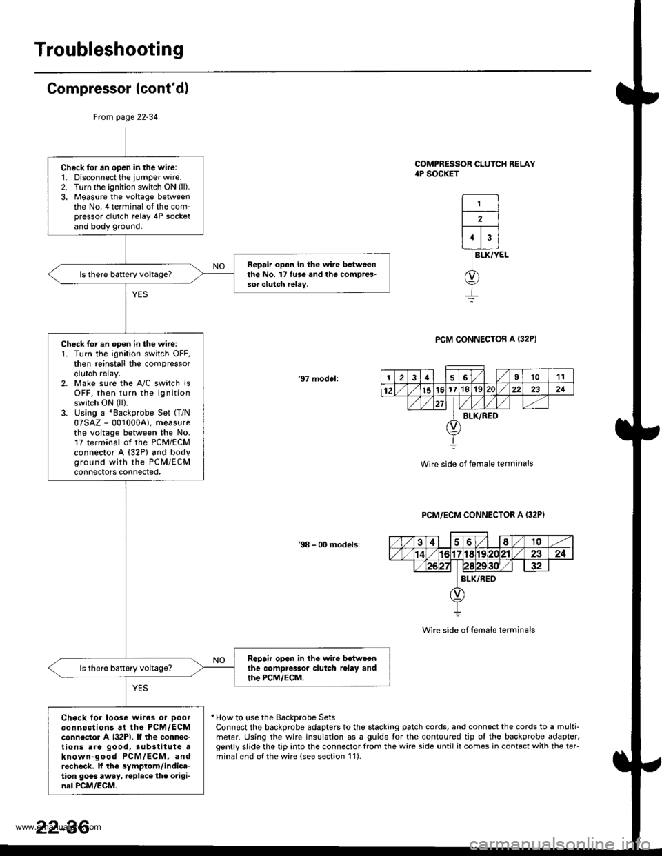
Compressor (cont'dl
COMPRESSOR CLUTCH RELAY4P SOCKET
1
2
43
BLK/YEL
PCM CONNECTOB A I32P)
'97 model:
Wire side of female terminals
PCM/ECM CONNECTOR A {32P}
38 - 00 models:
Wire side of {em6le terminals
* How to use the BackDrobe SetsConnect the backprobe adapters to the stacking patch cords, and connect the cords to a multi-meter. Using the wire insulation as a guide for the contoured tip ot the backprobe adapter,gently slide the tip into the connector trom the wire side until it comes in contact with the teFminalend o{the wire {see section l1).
Frcm page 22-34
Ch6ck for an open in the wire:1. Disconnect the jumper wire.2. Turn the ignition switch ON (ll).
3, Measure the voltage betweenthe No. 4 terminal ot the com'pressor clutch relay 4P socketand body ground.
Repair op.n in the wire betweenthe No. l7 fu3e and the compres-sor clutch ielay.
Check for an opon in the wire:1. Turn the ignition switch OFF,then reinstall the compressorclutch relay.2. Make sure the A"/C switch isOFF, then turn the ignitionswitch ON (ll).
3. Using a *Backprobe Set (T/N
07SAZ - 001000A), measurethe voltage between the No.17 terminal ol the PCM/ECMconnector A (32P) and bodyground with the PC M/ECMconnectors connected,
Repair open in lhe wire betwoonthe compressor clutch r6lay andthe PCM/ECM.
Check tor loose wires or Doorconnections at the PCM,/ECMconnecto. A {32P1. lf the connec-tions are good, sub3titute aknown-good PCM/ECM, androcheck. lf the symptom/indica-tion goas away, replac€ the origi-nal PCM/ECM.
126I1011
12151617'181S222321
BLK/RED
22-36
www.emanualpro.com
Page 1127 of 1395
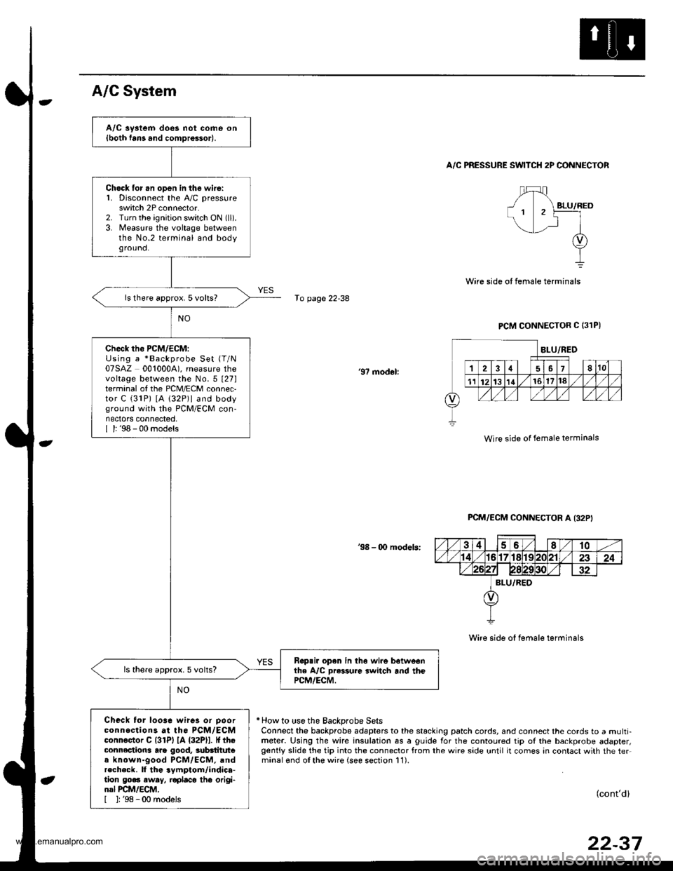
A/C aystem does not come on{both fans and comDrossor).
Ch6ck lor .n open in the wire:1. Disconnect the A,/C pressureswitch 2P connector.2. Turn the ignition switch ON (ll).
3. Measure the voltage betweenthe No.2 terminal and bodyground.
ls there approx. 5 volts?
check tho PcM/EcM:Using a *Backprobe Set (T/N
07SAZ 0010004). measure thevoltage between the No.5 t27lterminal of the PCM/ECM connec,tor C (31P) [A 132P)l and bodyground with the PCM/ECM con-nectors connected,I l: '98 - 00 models
Rop.ir open in th6 wire botweonthe A/C Dr*sure switch and thePCM/ECM.
ls there approx.5 volts?
Check tor loo3e wires or Doorconnections at the PCM/ECMconnoctor C l3lPl lA (32Pll. It theconnections arg good, 3ubdtitut€a known-good PCM/ECM, andrecheck. ll the 3ymptom/indica-tion go.. eway, r€placo thG origi-nal PCM/ECM,[ ]: '98 -00 models
A/C System
A/C PRESSURE SWITCH 2P CONNECTOR
fo page 22-38
PCM CONNECTOR C (31PI
'97 modol:
Wire side of female terminals
PCM/ECM CONNECTOR A I32P'
38 - 00 modeb:
Wire side of female terminals
* How to use the Backprobe SetsConnect the backprobe adapters to the stacking patch cords, and connect the cords to a multi-meter. Using the wire insulation as a guide for the contoured tip ol the backprobe adapter,gently slide the tip into the connector from the wire side until it comes in contact with the ter.minalond olthe wire (see section 11).
(cont'd)
22-37
www.emanualpro.com
Page 1130 of 1395
Troubleshooting
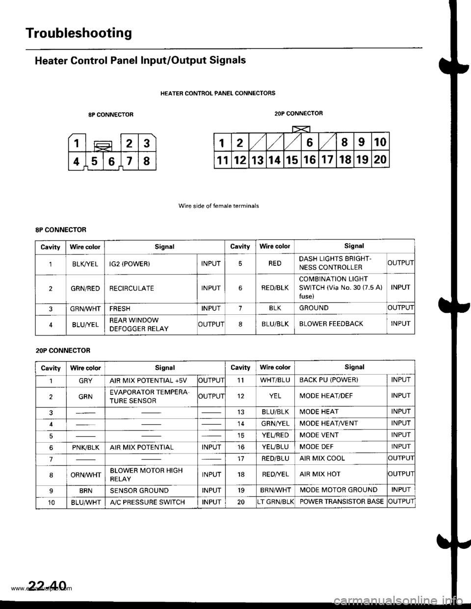
Heater Control Panel Input/Output Signals
HEATER CONTROL PANEL CONNECTORS
8P CONNECTOR
Wire side of female terminals
2OP CONNECTOR
8P CONNECTOR
Cavitylrvire cololSignalCavityWire cololSignal
'lBLK/TE LIG2 (POWER)INPUTREDDASH LIGHTS ERIGHT-
NESS CONTROLLERCUTPUT
2GRN/REDRECIRCULATEINPUTRE D/BLK
COMBINATION LIGHT
SWITCH (Via No. 30 (7.5 A)
fuse)
INPUT
GRN/VVHTFRESHINPUT1BLKGROUNDOUTPUT
BLUI/ELREAR WINDOW
DEFOGGER RELAYCUTPUT8BLU/BLKBLOWER FEEDBACKINPUT
20P CONNECTOR
CavityWire colorSignalCavityWire colorSignal
1GRYAIR MIX POTENTIAL +5VOUTPUT'llWHT/BLUBACK PU (POWER)INPUT
2GRNEVAPORATOR TEMPERA.
TURE SENSOROUTPUT12YELMODE HEAT/DEFINPUT
13BLU/BLKMODE HEATINPUT
14GRN/YELMODE HEAT/VENTINPUT
ICYEUREDMODE VENTINPUT
6PNI(BLKAIR MIX POTENTIALINPUTtoYEUBLUMODE DEFINPUT
717RED/BLUAIR MIX COOLOUTPUI
8ORNrur'HTBLOWER MOTOR HIGH
RELAYINPUT18RE D/VE LAIR MIX HOTOUTPUI
BRNSENSOR GROUNDINPUT'19BRNA/VHTIVIODE MOTOR GROUNDINPUT
10BLU,ryVHTA"/C PRESSURE SWITCHINPUT20T GRN/BLKPOWER TRANSISTOR BASECUTPUT
22-40
www.emanualpro.com
Page 1149 of 1395
Recovery
Use only service equipment that is U.L.-listed and is cer-
tified to meet the requirements of SAE J2210 to remove
HFC-134a (R-134a) from the air conditioner system.
CAUTION: Exposure to air conditioner refrigerant and
lubricant vapor or mist can irritate eyes, nose and
throat. Avoid brqathing the air conditioner retrigerant
and lubricant vapor or mist.
lf accidental system discharge occurs, ventilate work area
before resuming service.
R-134a service equipment or vehicle air conditioner sys-
tems should not be pressure tested or leak tested with
compressed arr.
@@ some mixtures of air and R-134a have been
shown to be combustible at elevated plessures and can
result in fire or explosion causing iniury or property dam-
age. Never use compressed air to pressure tect R-134a
service equipment or vehicle air conditioner systems.
Additional health and safety intormation may be obtained
from the refrigerant and lubricant manufacturers.
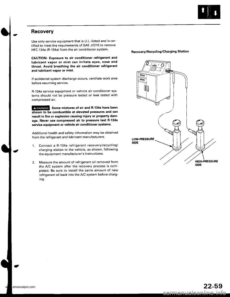
'1. Connect a R-134a refrigerant recove rylrecycling/
charging station to the vehicle, as shown, following
the equipment manufacturer's instructions
2. Measure the amount of refrigerant oil removed trom
the A,/C system after the recovery process is com-
oleted. Be sure to install the same amount of new
refrigerant oil back into the AVC system before charg-
inq.
Recovery/Recycling/Charging Station
22-59
www.emanualpro.com