Back HONDA CR-V 1998 RD1-RD3 / 1.G Manual Online
[x] Cancel search | Manufacturer: HONDA, Model Year: 1998, Model line: CR-V, Model: HONDA CR-V 1998 RD1-RD3 / 1.GPages: 1395, PDF Size: 35.62 MB
Page 760 of 1395
Transfer Assembly
18.
Reassembly (cont'dl
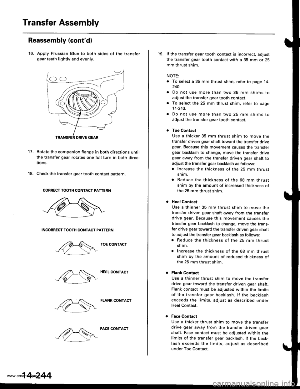
16. Apply Prussian Blue to both sides of the transfergear teeth lightly and evenly.
17.Rotate the companion flange in both directions until
the transfer gear rotates one full turn in both direc-
tions.
Check the transfer gear tooth contact pattern.
CORRECT TOOTH CONTACT PATTERN
NCONRECT TOOTH CONTACT PATTERN
TOE CONTACT
HEEL CONTACT
FLANK CONTACT
14-244
FACE CONTACT
19. lf the transfer gear tooth contact is incorrect, adjust
the transfer gear tooth contact with a 35 mm or 25
mm th rust shim.
NOTE:
. To select a 35 mm thrust shim, refer to page 14,240.
. Do not use more than two 35 mm shims to
adjust the transfer gear tooth contact.. To select the 25 mm thrust shim, refer to page
14-243.
. Do not use more than two 25 mm shims to
adjust the transfer gear tooth contact.
Toe Contact
Use a thicker 35 mm thrust shim to move the
transfer driven gear shaft toward the transfer drivegear. Because this movement causes the transfergear backlash to change, move the transfer drivegear away from the transfer driven gear shaft to
adjust the transfer gear backlash as follows:. Increase the thickness of the 25 mm thrust
shrm.
. Reduce the thickness of the 68 mm thrust
shim by the amount of increased thickness of
the 25 mm thrust shim.
Heel Contact
Use a thinner 35 mm thrust shim to move the
transfer driven gear shaft away from the transfer
drive gear. Because thjs movement causes the
transfer gear backlash to change, move the trans-
fer drive gear toward the transfer driven gear shaft
to adjust the transfer gear backlash as follows:. Reduce the thickness of the 25 mm thrust
shim.
. Increase the thickness of the 68 mm thrust
shim by the amount of reduced thickness ofthe 25 mm thrust shim.
Flank Contaqt
Use a thinner thrust shim to move the transfer
drive gear toward the transfer driven gear shaft.Flank contact must be adjusted within the limits
of the transfer gear backlash. lf the backlash
exceeds the limits, adjust as described underHeel Contact.
Face Contaqt
Use a thicker thrust shim to move the transfer
drive gear away from the transfer driven gear
shaft. Face contact must be adjusted within the
limits of the transfer gear backlash. lf the back-
lash exceeds the limits, adjust as described
under Toe Contact.
www.emanualpro.com
Page 761 of 1395
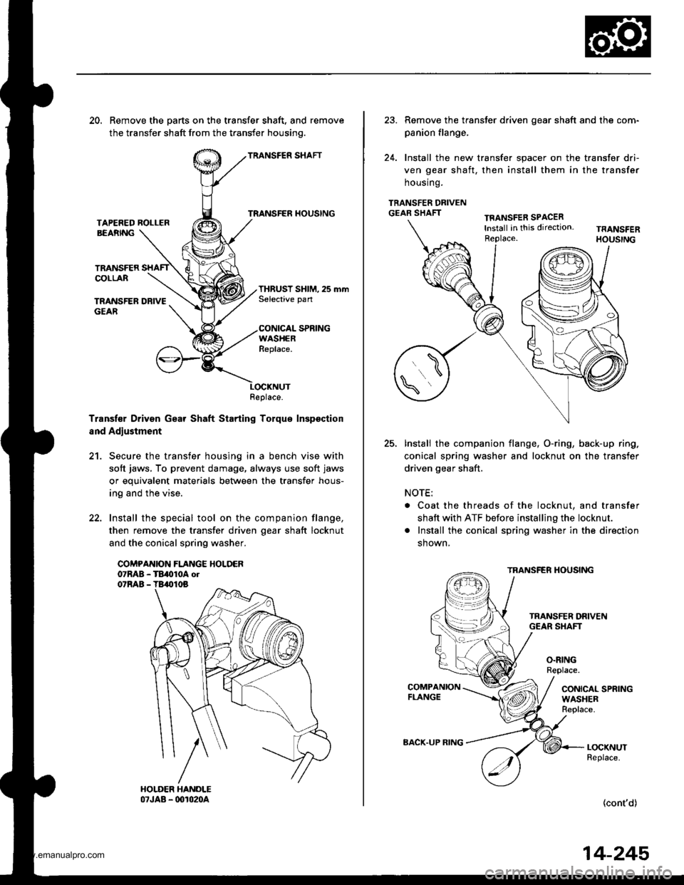
20. Remove the parts on the transfer shaft, and remove
the transfer shaft from the transfer housinq.
TRANSFER SHAFT
TRANSFER HOUSINGTAPEFED ROLLERBEARNG
TRANSFERCOLLAR
TRANSFER DRIVEGEAR
THRUST SHIM, 25 mmSelective pan
CONICAL SPRINGWASHERReplace.
Transf€r Driven Gear Shaft Starting Torque Inspsction
and Adjustment
21. Secure the transfer housing in a bench vise with
soft jaws, To prevent damage, always use soft jaws
or equivalent materials between the transfer hous-
ing and the vise.
22. Install the special tool on the companion flange,
then remove the transfer driven oear shaft locknut
and the conical spring washer.
COMPANION FLANGE HOLDER07RAB - TB,010A ol07RAB - TB,010B
Replace.
23. Remove the transter driven gear shaft and the com-
panion flange,
24. Install the new transfer spacer on the transfer dri-
ven gear shaft, then install them in the transfer
housrng.
TRANSFER DRIVENGEAR SHAFTTFANSFER SPACERlnstall in this direction.Replace.
25.Install the companion flange, O-ring, back-up ring.
conical spring washer and locknut on the transfer
driven gear shaft.
NOTE:
. Coat the threads of the locknut, and transfer
shaft with ATF before installing the locknut.
. Install the conical spring washer in the direction
shown,
TRANSFER HOUSING
O.RINGReplace.
CONICAL SPRINGWASHERReplace.
LOCKNUTReplace.
(cont'd)
BACK.UP RING
14-245
www.emanualpro.com
Page 805 of 1395
Rear Differential Assembly
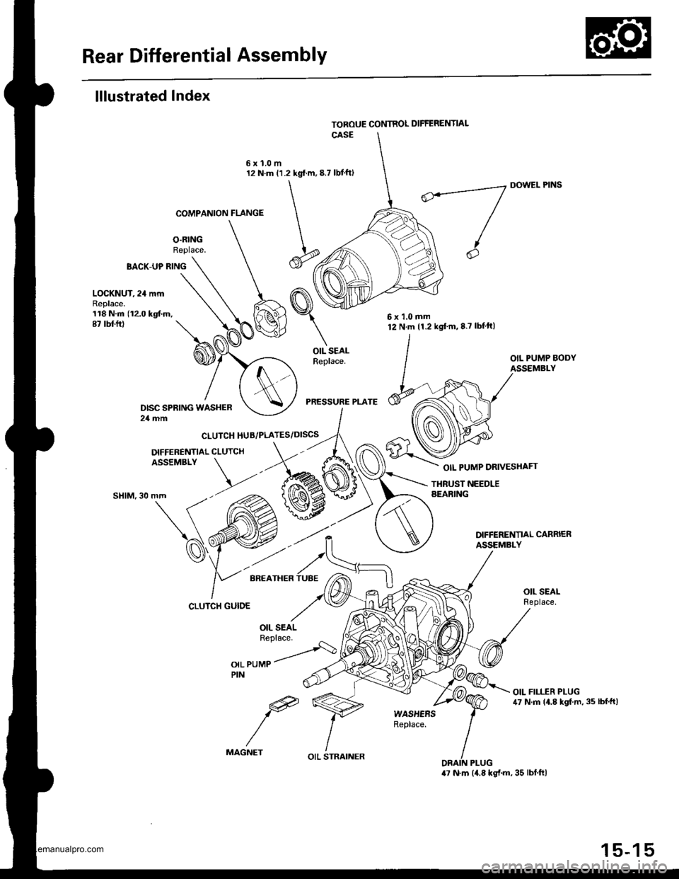
lllustrated Index
O.RINGReplace.
6xl.0m12 N.m (1.2 kgf m,8.7 lbt'ftl
BACK-UP RING
COMPANION FLANGE
CLUTCH HUB/PLATES/DISCS
DIFFERENNAL CLUTCHASSEMBLY
DOWEL PINS
OIL PUMP DRIVESHAFT
LOCKNUT, 24 mmReplace.118 N.m (12.0 kgtm.87 rbt ft)
OIL SEALReplace.
PRESSURE PLATE
THBUST NEEDLEAEARING""t",at\(
'd'
CLUTCH GUIDE
OIL PUMPPIN
e
MAGNET
6x1.0mm12 N.m 11.2 kgt'm,8.7 lbf'ft|
OIL STRAINER
15-15
www.emanualpro.com
Page 811 of 1395
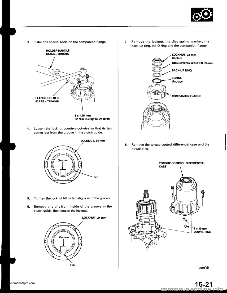
3. Installthe speclaltools on the companion flange,
HOIIIER HANDTIo'JAB - OO102nA
32 N m {3 3 tgt m,24lbf ftl
Loosen the locknut counterclockwise so that its tab
comes out from the groove in the clutch guide.
LOCKNUT, 24 mm
Tighten the locknut till its tab aligns with the groove.
Remove any dirt from inside of the groove in the
clutch guide, then loosen the locknut.
LOCKNUT. 2,1 mm
5.
6.
8 x 1.25 mm
Tab(cont'd)
7. Remove the locknut, the disc spring washer, the
back-up ring, the O-ring and the companion flange.
@r/v-.,.
ao/
U
rA*..-
zzft
h\@fr\
LOCKNUT, 24 mmFeplace.
DISC SPRING WASHER, 24 mm
BACX.UP RING
O.N|NGReplace.
COMPANION FLANGE
8.Remove the torque control differential case and the
dowel pins.
www.emanualpro.com
Page 814 of 1395
Rear Differential Assembly
Reassembly (cont'dl
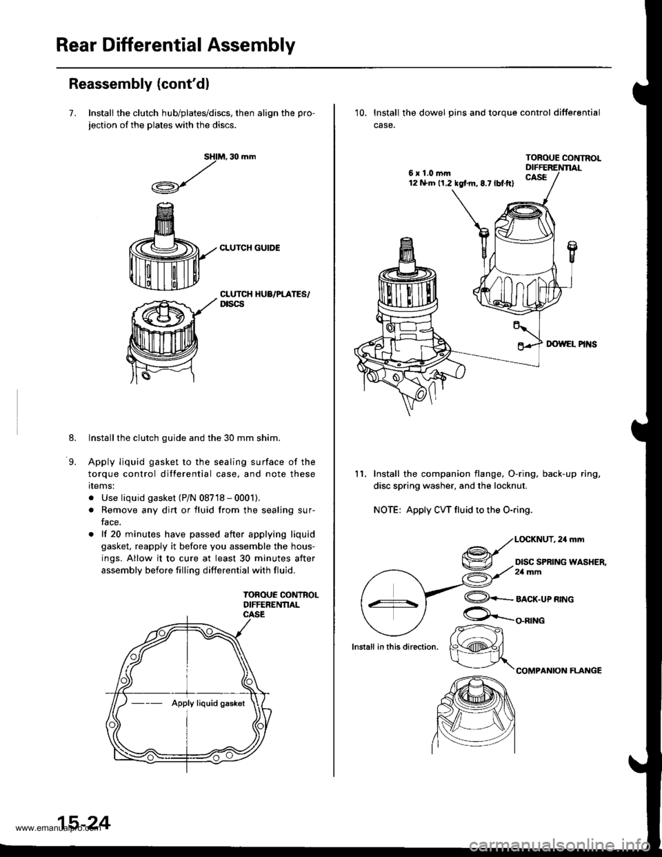
7. Install the clutch hub/plates/discs, then align the pro-
jection of the plates with the discs.
M, 30 mm
CLUTCH GUIDE
sHl
,/
.A-\,/r\-7
8.
9.
CLUTCH HUA/PLATES/Dtscs
Installthe clutch guide and the 30 mm shim.
Apply liquid gasket to the sealing surface of the
torque control differential case, and note these
rlems:
. Use liquid gasket (P/N 08718 - 0001).
. Remove any dirt or fluid from the sealing sur-
face.
. lf 20 minutes have passed after applying liquid
gasket, reapply it before you assemble the hous-
ings. Allow it to cure at least 30 minutes after
assembly before filling differential with fluid.
TOBOUE CONTROLDIFFERENNAL
--- Apply liquid gaskot
15-24
6x1.0mm12 N.m 11.2 tgf m,8.7lbt.ftl
10. lnstall the dowel pins and toroue control differential
case.
TOROUE CONTNOL
11. Install the companion flange, O-ring, back-up ring,
disc spring washer, and the locknut.
NOTE: Apply CW fluid to the O-ring.
,24mm
DISC SPRING WASHER,2a mm
lnstall in this direction.
@+-_alcr-upnwc
COMPANION FLAI{GE
/r-
K@#/
www.emanualpro.com
Page 852 of 1395
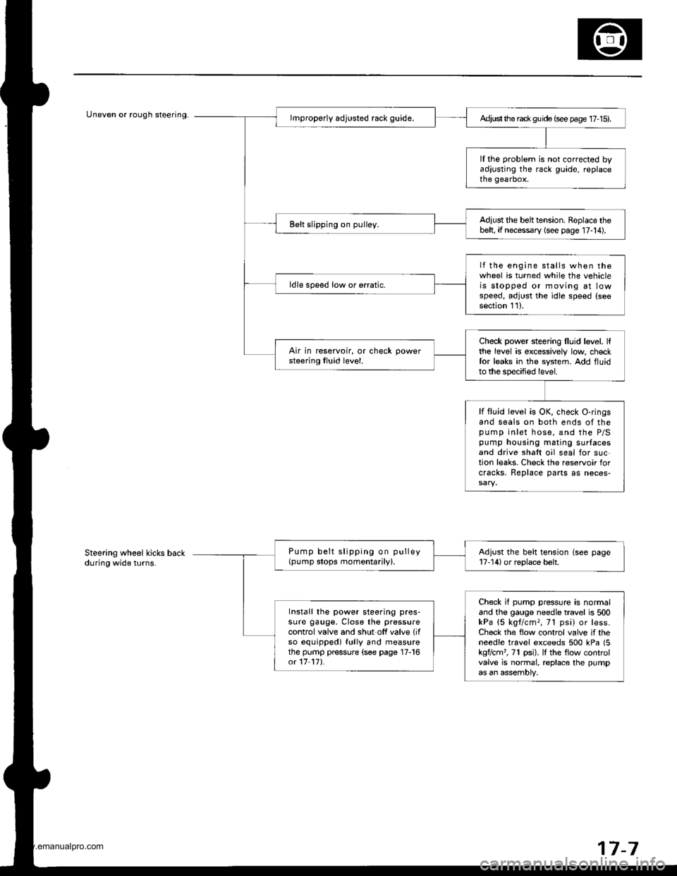
Uneven or rough steering.Ad,ust the rack gu ide (see page 17- 15).
ll the problem is not corrected byadjusting the rack guide, replacethe gearbox.
Adjust the belttension. Replace thebelt, if necessary (see page 17-14).Belt slipping on pulley.
lf the engine stalls when thewheel is turned while the vehicleis stopped or moving at lowspeed, adjust the idle speed (seesection 111.
ldle speed low or erratic.
Check power steering lluid level. lfthe level is excessively low checkfor leaks in the system. Add fluidto the specified level.
Air in reservoir, or check powersteering tluid level.
lf fluid level is OK, check O-ringsand seals on both ends of thepump inlet hose, and the P/Spump housing mating surlacesand drive shaft oil seal for suction leaks. Check the reservoir forcracks, Replace parts as neces-
Pump belt slipping on pulley(pump stops momentarily).Adjust the belt tension (see page17-14) or replace belt.
Check if pump pressure is normaland the gauge needle travel is 500kPa (5 kgl/cm,, 71 psi) or less.Check the flow control valve if theneedle travel exceeds 500 kPa (5kgflcm'�, 71 psi). lI the flow controlvalve is normal, replace the pumpas an assembly,
Install the power steering pres-sure gauge, Close the pressurecontrol valve and shut off valve (if
so equipped) fully and measurethe pump pressure (see page 17-16ot 17 17).
Steering wheel kicks backduring wide turns.
7-7
www.emanualpro.com
Page 860 of 1395
Rack Guide Adjustment
1.
6.
7.
5.
4.
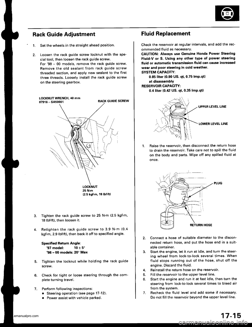
Set the wheels in the straight ahead position.
Loosen the rack guide screw locknut with the spe-
cialtool, then loosen the rack guide screw.
For'98 - 00 models, remove the rack guide screw.
Remove the old sealant from rack guide screw
threaded section, and apply new sealant to the first
three threads. Loosely install the rack guide screw
on the steering gearbox.
RACK GUIDE SCREW
LOCKNUT25 N.m
12.5 kgt m, 18lbtftl
Tighten the rack guide screw to 25 N.m (2.5 kgf'm,
18 lbf.ft), then loosen it.
Retighten the rack guide screw to 3.9 N'm (0.4
kgf.m, 2.9 lbf.ft), then back it off to specified angle.
Specified Return Anglo:
37 model: 10 r 5"'98 - 00 modeb: 20' Max
Tighten the locknut while holding the rack guide
screw.
Check for tight or loose steering through the com-
plete turning travel.
Perform following inspections:
. Steering operation (see page 17-12).
. Power assist with vehicle parked
Fluid Replacement
Check the reseryoir at regular intervals, and add the rec-
ommended fluid as necessary.
CAUTION: Always use Gsnuine Honda Power Steering
Fluid-V or S. Using any other type of power steering
tluid or automatic transmission fluid can cause increassd
wear and poor steering in cold w3athel.
SYSTEM CAPACITY:
0.85 liter {0.90 US. qt. 0.75 lmp.qtl
at disasssmbly
RESERVOIR CAPACITY:
0.,1 liter (0.42 US. gt, 0.35 lmp.qi)
UPPEN LEVEL LINE
LOWER LEVEL LINE
1.Raise the reservoir. then disconnect the return hose
to drain the reservoir. Take care not to spill the fluid
on the body and parts. Wipe off any spilled fluid at
once.
2, Connect a hose of suitable diameter to the discon-
nected return hose, and put the hose end in a suit-
able container.
3. Stan the engine. let it run at idle, and turn the steer-
ing wheel from lock-to-lock several times. When
fluid stops running out of the hose, shut off the
engine. Discard the fluid.
4. Beinstallthe return hose on the reservoar.
5. Fill the reservoir to the upper level line,
6. Start the engine and run it at fast idle. then turn the
steering from lock-to-lock several times to bleed air
from the system.
7. Recheck the fluid level and add some if necessary.
Do not fill the reservoir beyond the upper level line.
www.emanualpro.com
Page 871 of 1395
Power Steering Pump
Disassembly (cont'dl
1.
7.
9.
10.
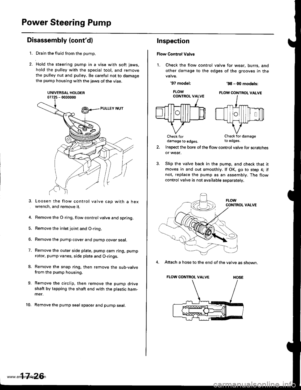
Drain the fluid from the pump.
Hold the steering pump in a vise with soft jaws.
hold the pulley with the special tool, and remove
the pulley nut and pulley. Be careful not to damagethe pump housing with the jaws of the vise.
UNIVERSAL HOLDER07725 - 0030000
Loosen the flow control valve cap with a hexwrench, and remove it.
Remove the O,ring, flow control valve and spring.
Remove the inlet joint and O-ring.
Remove the pump cover and pump cover seal.
Remove the outer side plate, pump cam ring, pump
rotor, pump vanes, side plate and O-rings.
Remove the snap ring, then remove the sub-valvefrom the pump housing.
Remove the circlip, then remove the pump driveshaft by tapping the shaft end with the ptastic ham-mer.
Remove the pump seal spacer and pump seal.
17-26
Inspection
Flow Control Valve
1. Check the flow control valve for wear, burrs, and
other damage to the edges of the grooves in thevalve.
'97 model:
FLOWCONTROL VALVE
Check fordamage to edges.
'98 - 0O mod€ls:
FLOW CONTBOL VALVE
Check for damageto edges.
Insp€d the bore of the flow control valve tor scratchesor wear.
Slip the valve back in the pump, and check that itmoves in and out smoothly. lf OK, go to step 4; ifnot, replace the pump as an assembly. The flowcontrolvalve is not available separately.
CONTROL VALVE
4. Attach a hose to the end of the valve as shown.
FLOW CONTROL VALVE HOSE
www.emanualpro.com
Page 878 of 1395
REAR MOUNT
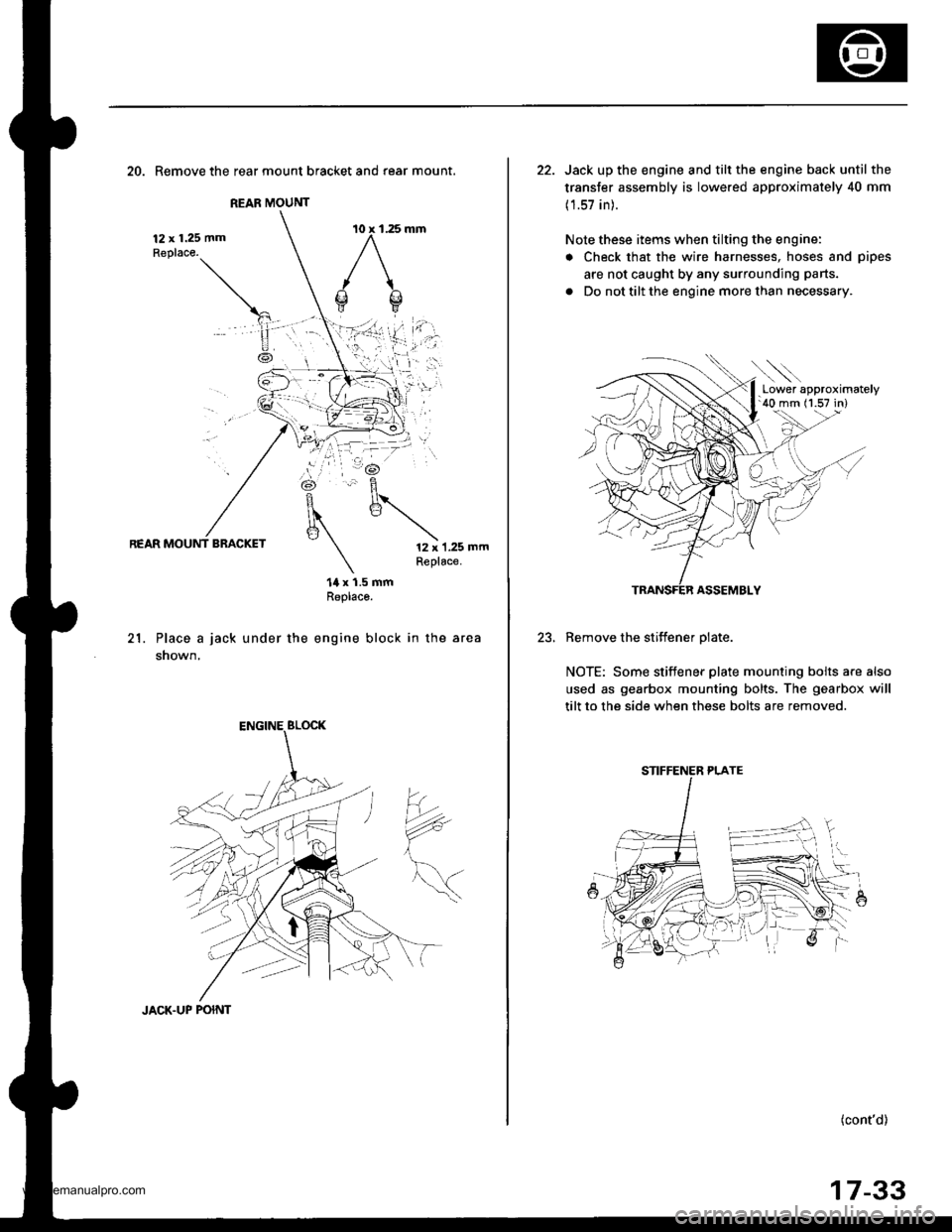
20. Remove the rear mount bracket and rear mount.
12 x 1.25 mmReplace.
REAR MOUNT BRACKET12 x 1.25 mmReplace.
21.
14 x 1.5 mmReplaco.
Place a jack under the engine block in the area
shown,
?*
JACK.UP POINT
17-33
22. Jack up the engine and tilt the engine back until the
transfer assembly is lowered approximately 40 mm
(1.57 in).
Note these items when tilting the engine:
. Check that the wire harnesses, hoses and pipes
are not caught by any surrounding parts.
. Do not tilt the engine more than necessary.
ASSEMBLY
Remove the stiffener olate.
NOTE: Some stiffener plate mounting bolts a.e also
used as gearbox mounting bolts. The gearbox will
tilt to the side when these bolts are removed.
(cont'd)
.Lower approximately'40 mm (1.57 in)
STIFFENER PLATE
www.emanualpro.com
Page 880 of 1395
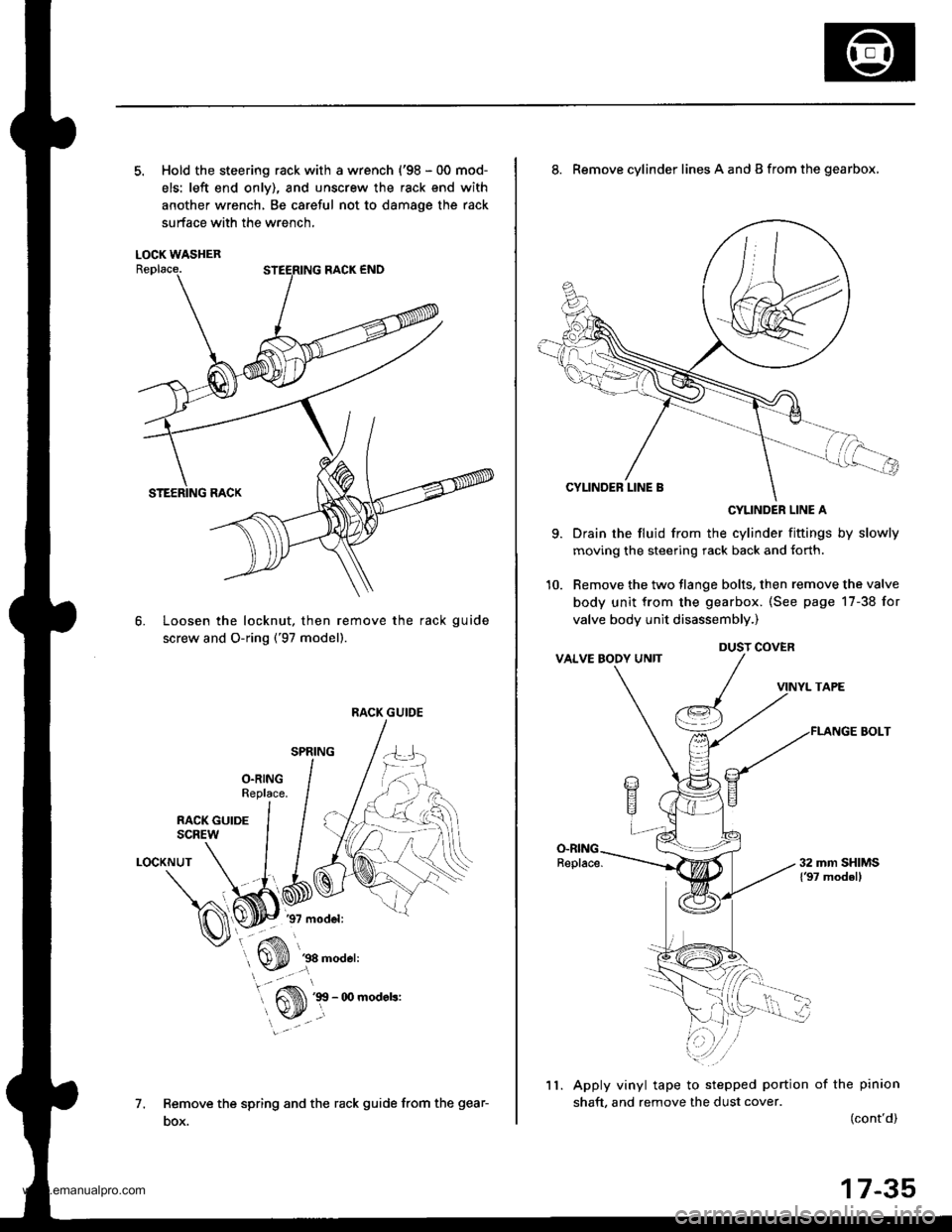
5. Hold the steering rack with a wrench {'98 - 00 mod-
els: left end onlv), and unscrew the rack end with
another wrench, Be careful not to damage the rack
surface with the wrench,
LOCK WASHER
Loosen the locknut, then remove the rack guide
screw and O-ring ('97 model).
6.
1.
LOCKNUT
Remove the spring and the rack guide from the gear-
DOX.
RACK GUIDE
9.
8. Remove cylinder lines A and B from the gearbox,
CYLINDER LINE A
Drain the fluid from the cylinder fittings by slowly
moving the steering rack back and {orth.
Remove the two tlange bolts, then remove the valve
body unit from the gearbox. (See page 17-38 for
valve body unit disassembly.)
VINYL TAPE
FLANGE BOLT
Apply vinyl tape to stepped portion of the pinion
shaft, and remove the dust cover.(cont'd)
DUST COVER
11.
17-35
www.emanualpro.com