Gear HONDA CR-V 1998 RD1-RD3 / 1.G Service Manual
[x] Cancel search | Manufacturer: HONDA, Model Year: 1998, Model line: CR-V, Model: HONDA CR-V 1998 RD1-RD3 / 1.GPages: 1395, PDF Size: 35.62 MB
Page 468 of 1395
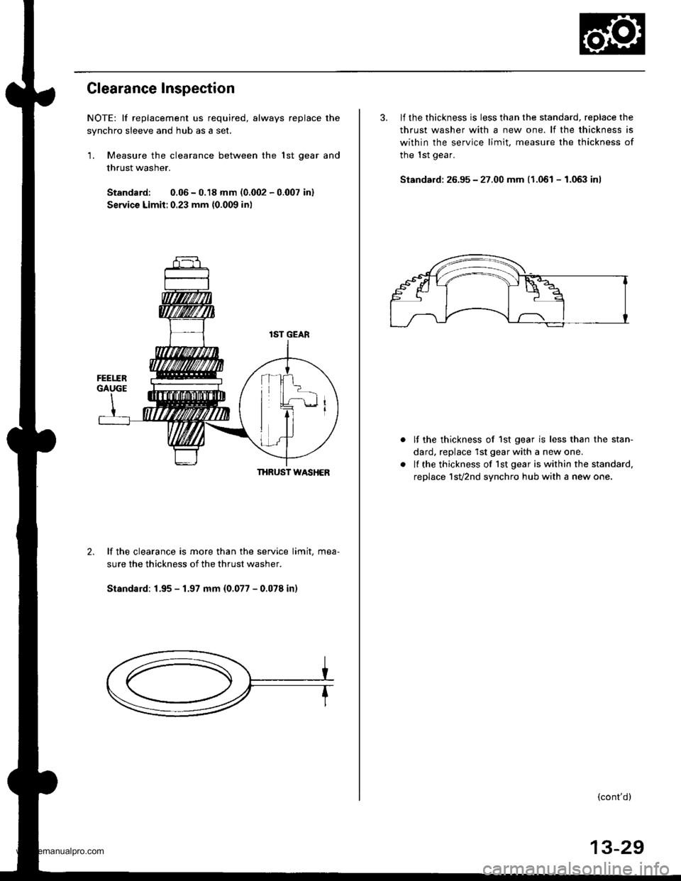
Clearance Inspection
NOTE: lf replacement us required, always replace the
synchro sleeve and hub as a set.
1. Measure the clearance between the lst oear and
thrust washer.
Standard: 0.06 - 0.18 mm (0.@2 - 0.007 in)
Servica Limit:0.23 mm {0.009 in)
THRUST WASHER
2.lf the clearance is more than the service limit, mea-
sure the thickness of the thrust washer.
Standsrd: 1.95 - 1.97 mm (0.077 - 0.078 in)
3. lf the thickness is less than the standard, reDlace the
thrust washer with a new one. lf the thickness is
within the service limit, measure the thickness of
the 1st gear.
Standard: 26.95 - 27.00 mm (1.061 - 1.063 inl
lf the thickness of 1st gear is less than the stan-
dard, replace 1st gear with a new one.
lf the thickness of lst gear is within the standard.
replace 1sv2nd synchro hub with a new one.
{cont'd}
13-29
www.emanualpro.com
Page 469 of 1395
Countershaft Assembly
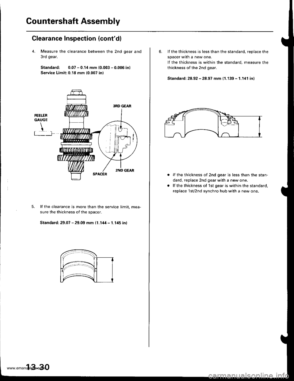
Clearance Inspection (cont'dl
4. Measure the clearance between the 2nd qear and
3rd gear.
Standard: 0.07 - 0.1,1 mm (0.003 - 0.006 inl
Service Limit:0.18 mm (0.007 inl
FEET.ERGAUGE
!t .�-]�
lf the clearance is more than the service limit. mea-
sure the thickness of the spacer.
Standard: 29.07 - 29.09 mm (l.14il - 1.145 inl
13-30
6. lf the thickness is less than the standard, reDlace the
spacer wrln a new one.
lf the thickness is within the standard, measure the
thickness of the 2nd gear.
Standald: 28.92 - 28.97 mm (1.139 - 1.141 in)
lf the thickness of 2nd gear is less than the stan-
dard, replace 2nd gear with a new one.
lf the thickness of lst gear is within the standard,
replace 1sv2nd synchro hub with a new one.
www.emanualpro.com
Page 470 of 1395
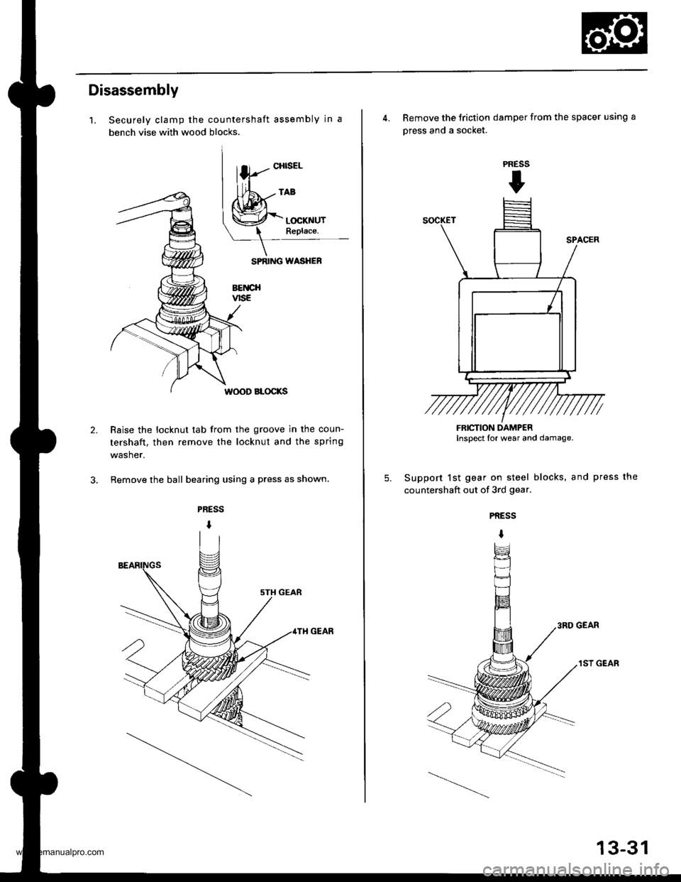
Disassembly
1.
2.
Securely clamp the countershaft assembly in a
bench vise with wood blocks.
SPRIiIG WASHEF
BETICHvtsE
W(X)D BLOCKS
Raise the locknut tab from the groove in the coun-
tershaft, then remove the locknut and the spring
washer.
Remove the ball bearing using a press as shown.
CHISEL
4. Remove the Jriction damper from the spacer using a
press and a socket.
Support lst gear on steel blocks, and press the
countershaft out of 3rd gear.
PRESS
t
5.
PRESS
I
3RD GEAR
1ST GEAR
FRICTION DAMPERInspect lor wear and damage.
13-31
www.emanualpro.com
Page 471 of 1395
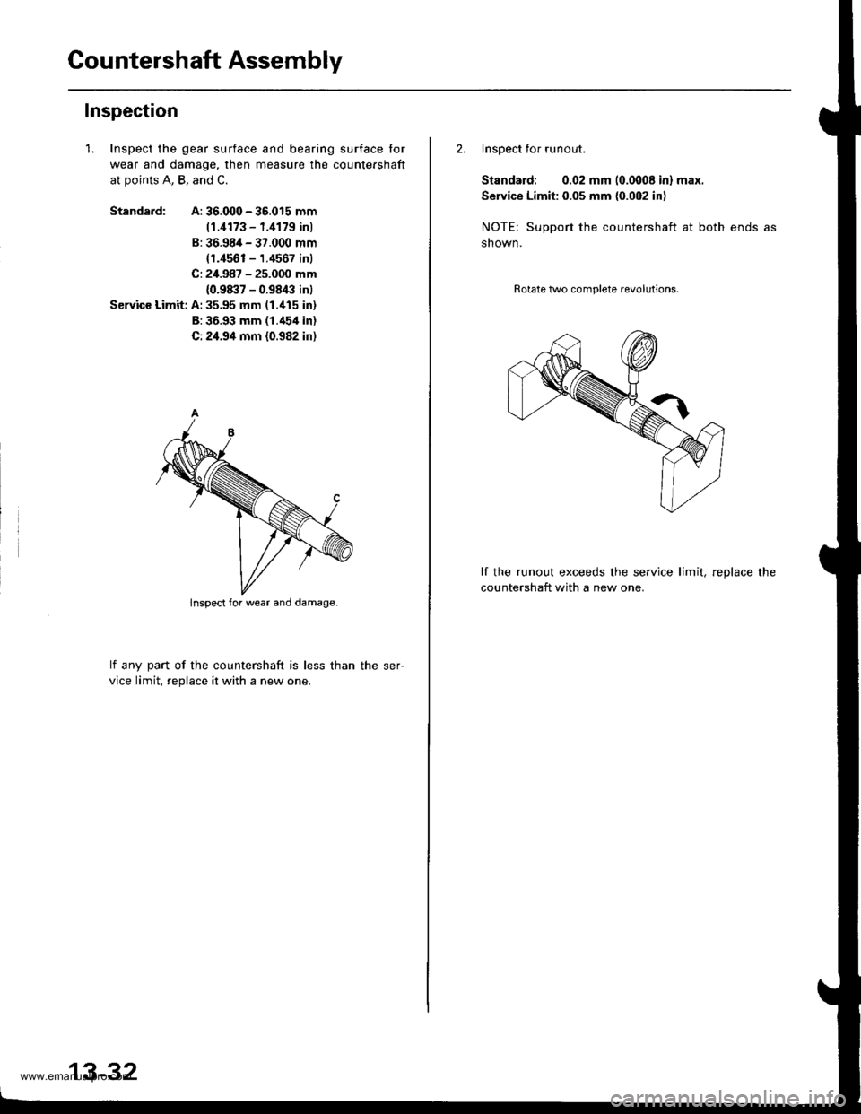
Countershaft Assembly
Inspection
1. Inspect the gear surface and bearing surface Ior
wear and damage, then measure the countershaft
at points A, B, and C.
Standa.d:A: 36.000 - 36.015 mm
11.,1173 - f.ill79 inl
B: 36.98/t - 37.000 mm
{r.4561 - 1.4567 inl
C: 24.987 - 25.000 mm
{0.98:17 - 0.9843 inl
Servics Limit: A:35,95 mm (1.'115 in)
B: 36.93 mm (1.454 in)
C: 24.94 mm (0.982 in)
lf anv part of the countershaft is less than the ser-
vice limit. reolace it with a new one.
lnspect for wear and damage.
13-32
2. Inspect for runout.
Standard: 0.02 mm 10.0008 inl max.
Service Limit: 0.05 mm {0.002 inl
NOTE: Support the countershaft at both ends as
shown.
Rotate two complete revolutions.
lf the runout exceeds the service limit, reDlace the
countershaft with a new one.
www.emanualpro.com
Page 472 of 1395
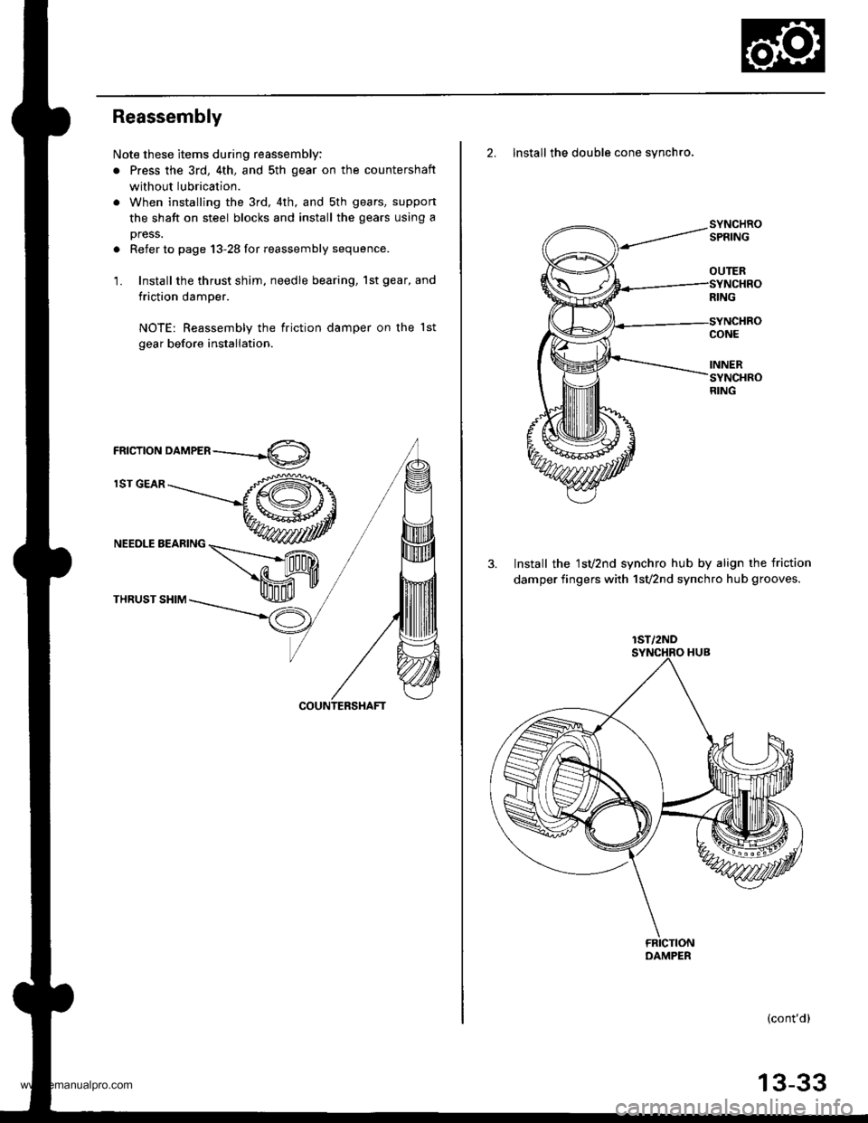
Reassembly
Note these items during reassembly:
. Press the 3rd, 4th, and sth gear on the countershaft
without lubrication.
. When installing the 3rd, 4th. and sth gears, suppon
the shaft on steel blocks and install the gears using a
press.
. Refer to page 13-28 for reassembly sequence.
1. Install the thrust shim, needle bearing, 1st gear, and
friction damper.
NOTE: Reassembly the friction damper on the lst
gear before installation.
rnrcrroru orn,leen ----.-4O)
lST GEAR
NEEDLE BEARING
THRUST SHIM
2. Install the double cone synchro.
3. Install the 1sv2nd synchro hub by align the friction
damper fingers with 1svznd synchro hub grooves.
(cont'd)
OUTER
lST/2ND
13-33
www.emanualpro.com
Page 473 of 1395
Countershaft Assembly
Reassembly (cont'dl
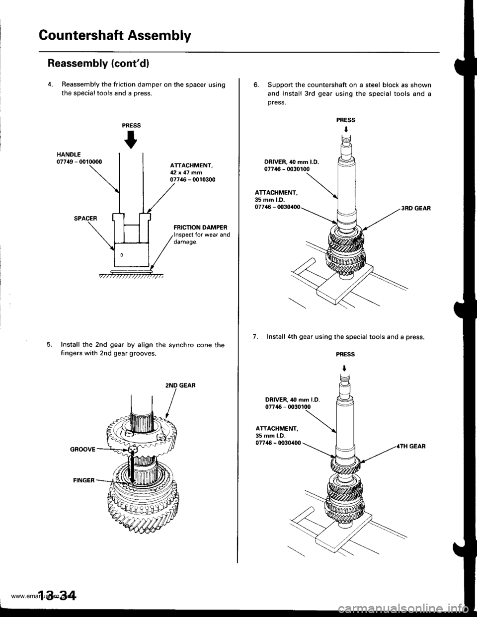
4. Reassembly the friction damper on the spacer using
the sDecialtools and a Dress.
PRESS
t
ATTACHMENT,U2t 47 mfi07716 - 0010300
FRICTION DAMPERInspect for wear anddamage.
Install the 2nd gear by align the
fingers with 2nd gear grooves.
synchro cone the
GROOVE
13-34
6. Support the countershaft on a steel block as shown
and install 3rd gear using the special tools and a
press.
3RO GEAR
7. lnstall 4th gear using the special tools and a press.
PRESS
I
PRESS
t
ATTACHMENT,35 mm LD.07746 - 0030,100
www.emanualpro.com
Page 474 of 1395
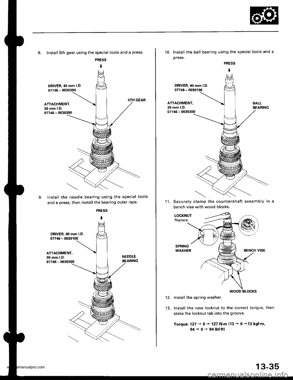
8. Install sth gear using the special tools and a press.
PRESS
I
DRIVER, 40 mm l.D.
07715 - 0030300
ATTACHMENT,30 mm LD.077,16 - 0030300
LInstall the needle bearing using the special tools
and a press, then installthe bearing outer race
PRESS
I
DRIVER. 40 mm l.D.077{6 - 0030100
ATTACHMENT,30 mm l.D.07746 - 0030300
NEEDLEBEASING
10. Install the ball bearing using the special tools and a
press.
PRESS
I
DRIVER. 40 mm LD.07746 - 0030100
ATTACHMENT,30 mm LD.077a6 - 0030300
11.Securely clamp the countershaft assembly in
bench vise with wood blocks.
LOCKNUTReplace.
Install the spring washer.
Install the new locknut to the correct torque, then
stake the locknut tab into the groove.
Torque: 127 + 0 + 127 N.m 113 - 0 +13 kgf.m,
94+0-94|bf.ft)
12.
wooD slocKs
13-35
www.emanualpro.com
Page 475 of 1395
Synchro Sleeve, Synchro Hub
Inspection
1.Inspect gear teeth on all synchro hubs and synchro
sleeves for rounded off corners, which indicate
Install each synchro hub in its mating synchro
sleeve, and check for freedom of movement.
NOTE: lf replacement is required, always replace
the synchro sleeve and synchro hub as a set.
SYNCHROSLEEVE
SYNCHBOHUB
13-36
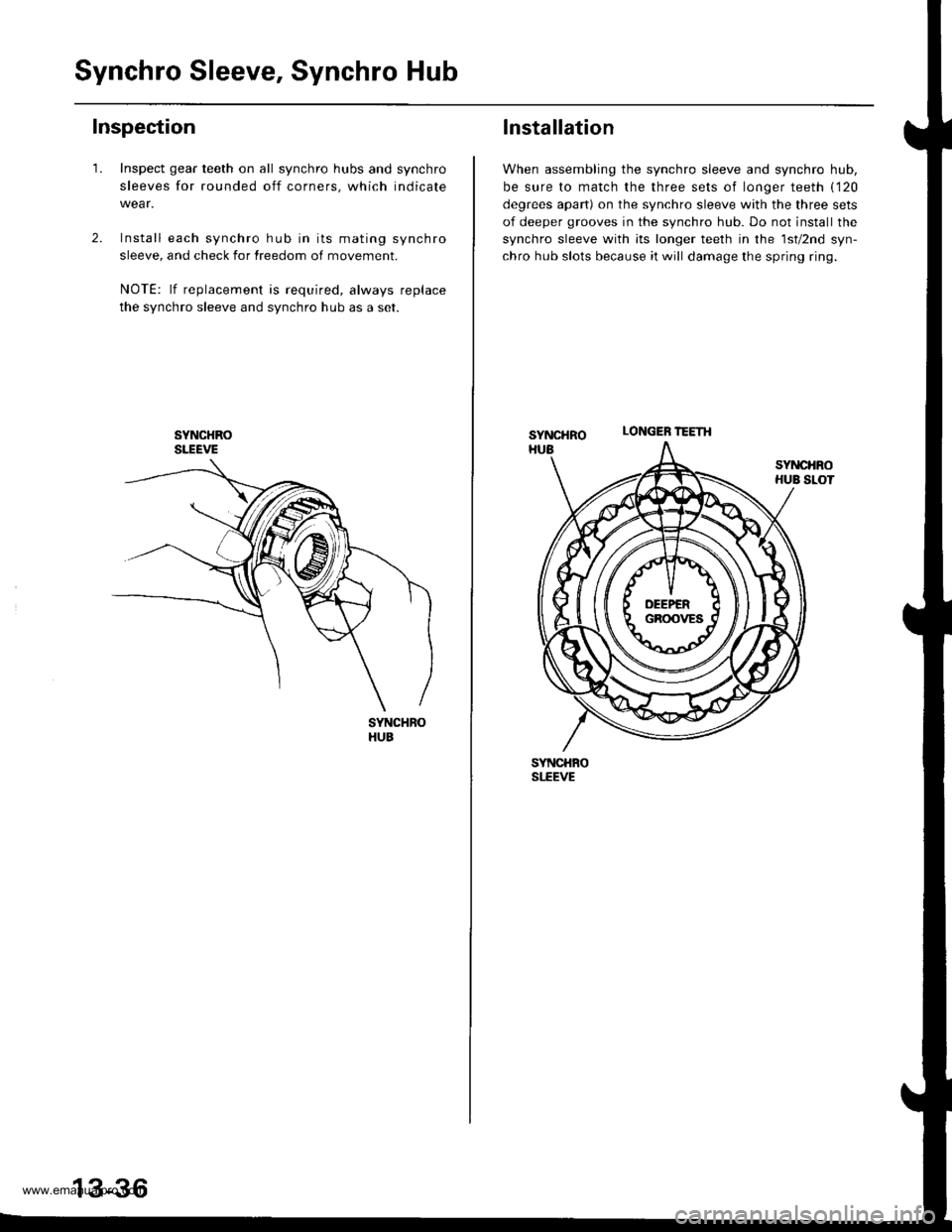
LONGER ?EETH
Installation
When assembling the synchro sleeve and synchro hub,
be sure to match the three sets of longer teeth ('120
degrees apart) on the synchro sleeve with the three sets
of deeper grooves in the synchro hub. Do not installthe
synchro sleeve with its longer teeth in the lsv2nd syn-
chro hub slots because it will damage the spring ring.
SYNCHRO
SYNCHBOSI.EEVE
www.emanualpro.com
Page 476 of 1395
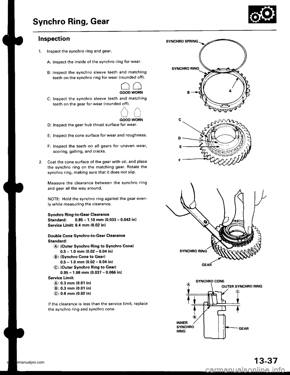
Synchro Ring, Gear
Inspection
Inspect the synchro ring and gear.
Ar lnspect the inside of the synchro ring for wear.
B: lnspect the synchro sleeve teeth and matching
teeth on the synchro ring for wear (rounded of0.
CCGOOO WORN
Cr Inspect the synchro sleeve teeth and matching
teeth on the gear tor wear (rounded off).
,,
u (-l
GOOO WORN
D: Inspect the gear hub thrust surface for wear.
E: Inspect the cone surface lor wear and roughness.
F: Inspect the teeth on all gears for uneven wear,
scoring, galling, and cracks.
2. Coat the cone surface of the gear with oil, and place
the synchro ring on the matching gear. Rotate the
synchro ring, making sure that it does not slip.
Measure the clearance between the synchro ring
and gear allthe way around.
NOTE: Hold the synchro ring against the gear even-
ly while measuring the clearance.
Synchro Ring-to-Gear Clearance
Standard: 0.85 - 1.10 mm (0.033 - 0.0,lil in)
Service Limit: 0.,1 mm 10.02 inl
Double Cone Synchro-lo-Goar Clearance
Standard:
@: {Outer Synchro Ring to Synchto Conel
0.5 - 1.0 mm (0.02 - 0.04 in)
€): {synchro cone to Geal)
0.5 - 1.0 mm (0.02 - 0.0i1inl
@: louter Synchro Ring to Gearl
0.95 - 1.68 mm (0.037 - 0.056 inl
Service Limit:
@: 0.3 mm (0.01 inl
@: 0.3 mm {0.01 in}
@: 0.6 mm {0.02 in)
lf the clearance is less than the service limit, replace
the synchro ring and synchro cone.
SYNCHRO SPRING
SYNCHRO
1.
OUTER SYNCHRO RING
13-37
www.emanualpro.com
Page 477 of 1395
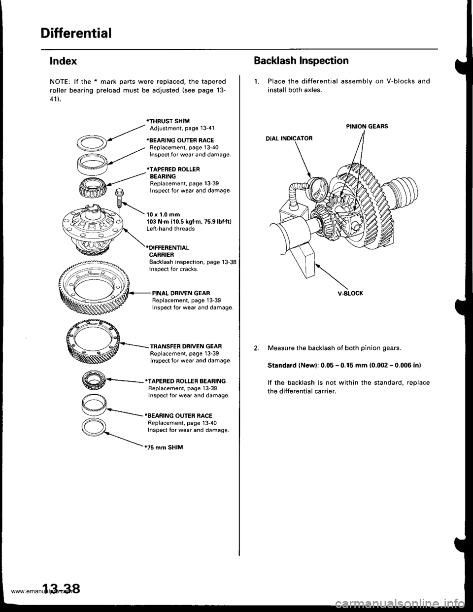
Differential
lndex
NOTE: lf the * mark parts were replaced, the tapered
roller bearing preload must be adjusted (see page 13-
41).
*THRUST SHIMAdiustment, Page 13'41
+BEARING OUTER RACEBeplacement, page 13 40Inspect for wear and damage.
*TAPERED ROLLERBEARINGReplacement, page l3-39Inspect for wear and damage.
10 x 1.0 mm103 N.m {10.5 kgf m, 75.9 lbf.ft}Left-hand threads
CARRIERBacklash inspection, page 13 38lnspect for cracks.
FINAL DRIVEN GEARReplacement, page 13-39Inspect for wear and damage
TRANSFER DRIVEN GEARReplacement, page 13-39Inspect {or wear and damage.
,,4\
W-
*TAPERED ROLLER BEARINGBeplacement, page 13'39Inspect for wear and damage.
IEEARING OUTER RACEReplacement, page 13-40Inspect for wear and damage.
.75 mm SHIM
13-38
Backlash Inspection
1. Place the differential
install both axles.
assembly on V-blocks and
PINION GEARS
V-BLOCK
2. Measure the backlash ot both pinion gears.
Standard (Newl: 0.05 - 0.15 mm (0.002 - 0.006 inl
lf the backlash is not within the standard, reolace
the differential carrier.
www.emanualpro.com