ECU HONDA CR-V 1998 RD1-RD3 / 1.G Repair Manual
[x] Cancel search | Manufacturer: HONDA, Model Year: 1998, Model line: CR-V, Model: HONDA CR-V 1998 RD1-RD3 / 1.GPages: 1395, PDF Size: 35.62 MB
Page 786 of 1395
Shift Lever
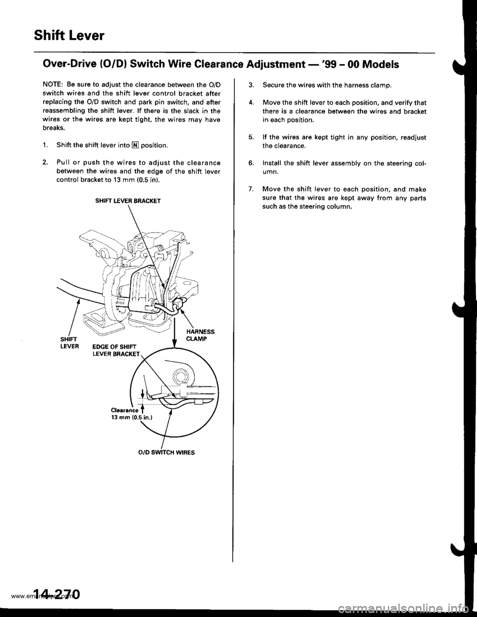
Over-Drive (O/Dl Switch Wire Clearance Adjustment -'99 - 00 Models
NOTE: Be sure to adjust the clearance between the O/D
switch wires and the shift lever control bracket after
replacing the O/D switch and park pin switch, and after
reassembling the shift lever. lf there is the slack in the
wires or the wires are kept tight, the wires may have
Dreaks.
1. Shift the shift lever into E positron.
2. Pull or push the wires to adjust the clearance
between the wires and the edge of the shift lever
control bracket to 13 mm (0.5 in).
SHIFT LEVER BRACKET
14-270
7.
Secure the wires with the harness clamp.
Move the shift lever to each position, and verify that
there is a clearance between the wires and bracket
in each position.
lf the wires are kept tight in any position, read.iust
the clearance.
Install the shift lever assembly on the steering col-
umn.
Move the shift lever to each position, and make
sure that the wires are kept away from any parts
such as the steering column.
www.emanualpro.com
Page 788 of 1395
Shift Gable
Adjustment
SRS components are located in this area. Review the SRS
component locations, precautions, and procedures in the
SRS section (241 before performing repairs or service.
1. Release the steering tilt lever.
2. Remove the access cover from the lower column
cover.
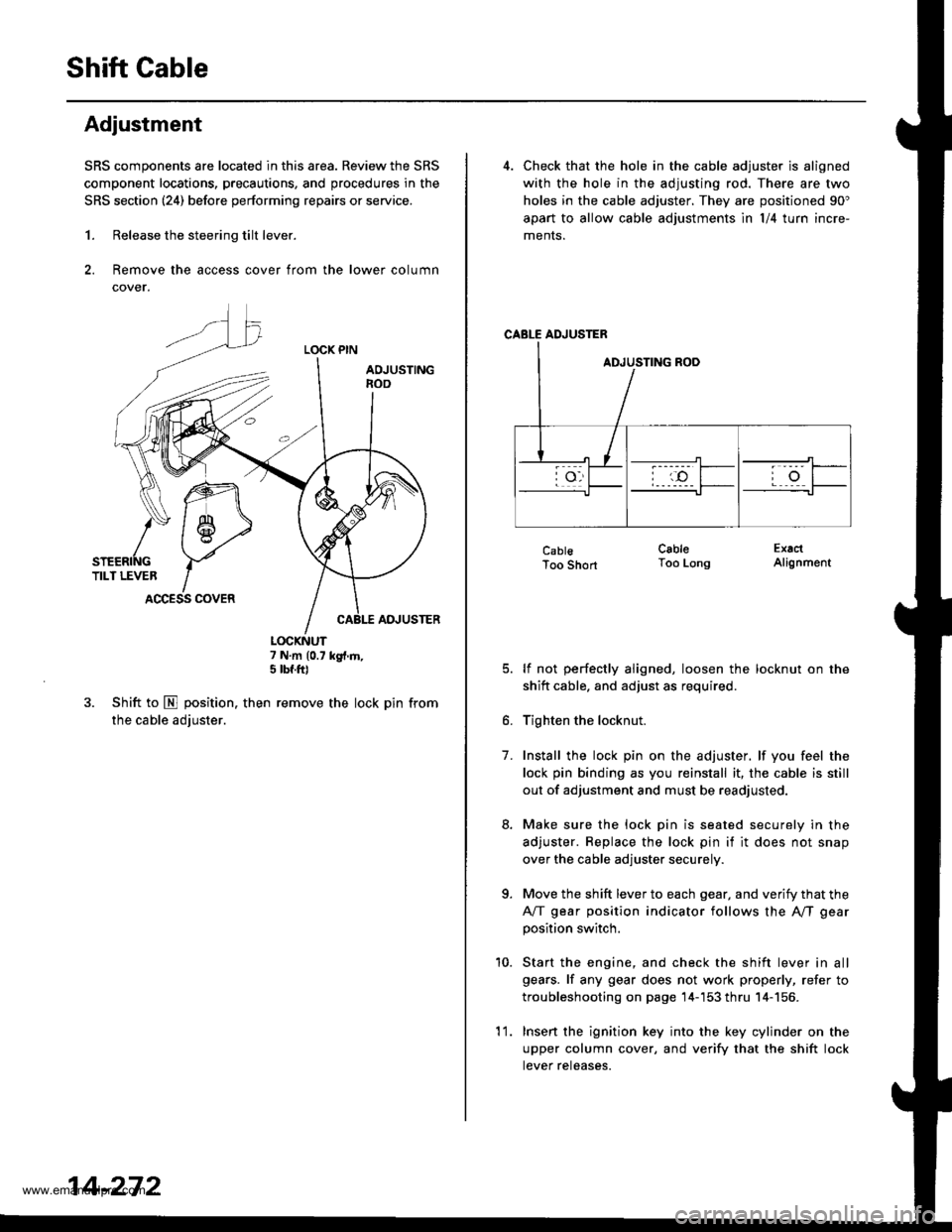
LOCK PIN
AOJUSTINGnoo
ADJUSTER
7 N.m (0.7 kg{.m,5 tbf.ft)
3. Shift to E position. then remove the lock pin from
the cable adjuster.
K\ffi
/* 1 6-,>
snenrftc YTILT LEVER IACCESS COVER
14-272
'l 1.
4. Check that the hole in the cable adjuster is aligned
with the hole in the adjusting rod. There are two
holes in the cable adjuster. They are positioned 90"
apart to allow cable adjustments ln l/4 turn incre-
ments.
CABLE ADJUSTER
CablsToo Short
lf not perfectly aligned, loosen the locknut on the
shitt cable. and adjust as required.
Tighten the locknut.
Install the lock pin on the adjuster. lf you feel the
lock pin binding as you reinstall it, the cable is still
out of adjustment and must be readjusted.
Make sure the lock pin is seated securely in the
adjuster. Replace the lock pin if it does not snap
over the cable adjuster securely.
Move the shift lever to each gear, and verify that the
A/T gear position indicator follows the A"/T gear
position switch.
Start the engine, and check the shift lever in all
gears. lf any gear does not work properly, refer to
troubleshooting on page 14-'153 thru 14-156.
Insert the ignition key into the key cylinder on the
upper column cover, and verify that the shift lock
tever reteases.
CableToo LongExactAlignment
7.
a
10.
www.emanualpro.com
Page 789 of 1395
Replacement
SRS components are located in this area. Review the SRS
component locations, precautions, and procedures in the
SRS section {24} before performing repairs or service.
1. Remove the instrument panel lower cover and the
column covers (see section 17).
2. Shift to E position, then remove the lock pin from
the cable adiuster.
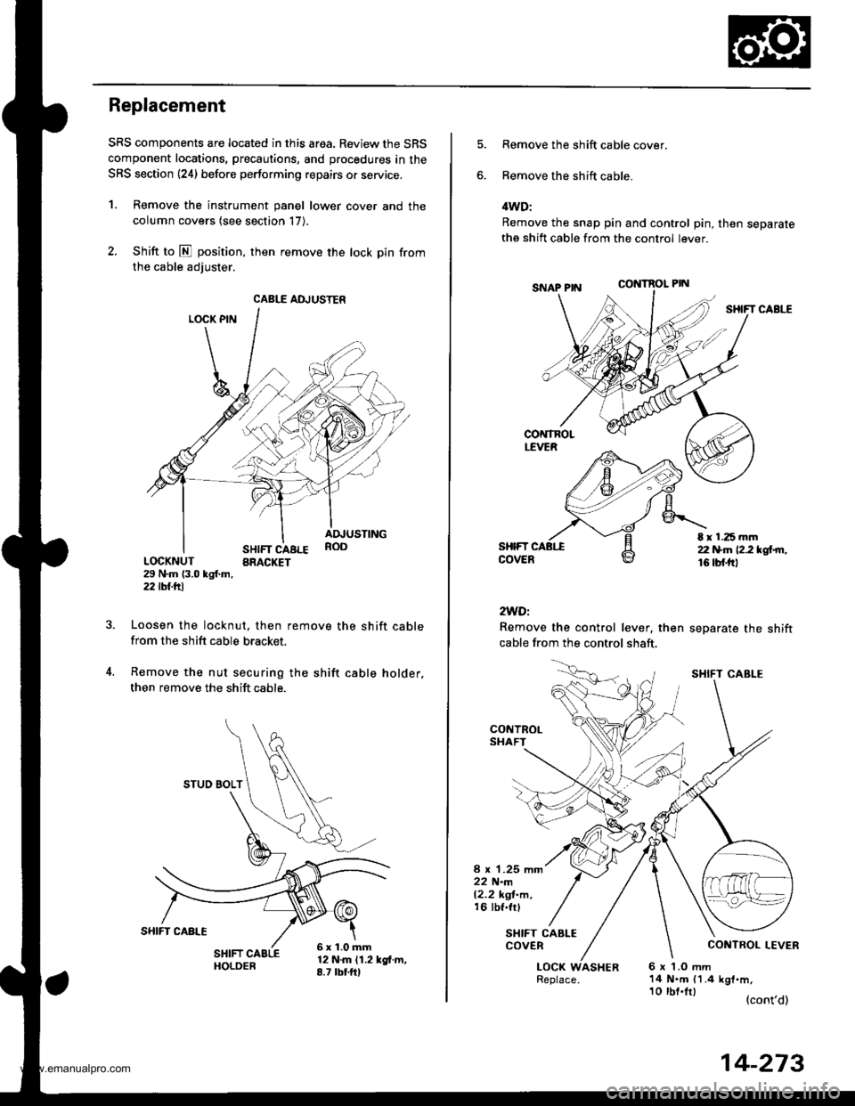
LOCK PIN
SHIFT CABLEBRACKET
ADJUSTINGROO
LOCKNUT29 N.m {3.0 kgl.m,2j2lbf.trl
Loosen the locknut, then remove the shift cablefrom the shift cable bracket.
Remove the nut securing the shift cable holder,
then remove the shift cable.
12 N.m {1.2 kgf.m,8.7 tbtfrl
CABLE ADJUSTER
STUO BOLT
6x1.0mm
Remove the shift cable cover.
Remove the shift cable.
4WD:
Remove the snap pin and control pin, then separatethe shift cable from the control lever.
CONTROL PIN
SHIFT CABLE
SHIFTCOVER
2WDi
Remove the control lever, then
cable from the control shaft.
separate the shift
t r 1.25 mm22 N.n 12.2 *glrn.16 tbf.trl
CONTROLSHAFT
8 x 1.25 mm22 N.m12.2 kgl-m,16 tbf.frl
SHIFT CABLECOVER
LOCK WASHER6x LOmm14 N.m {1.4 kgf.m,
(cont'd)
SHIFT CABI-E
10 tbt.lrl
14-273
www.emanualpro.com
Page 790 of 1395
Shift Gable
Replacement (cont'd)
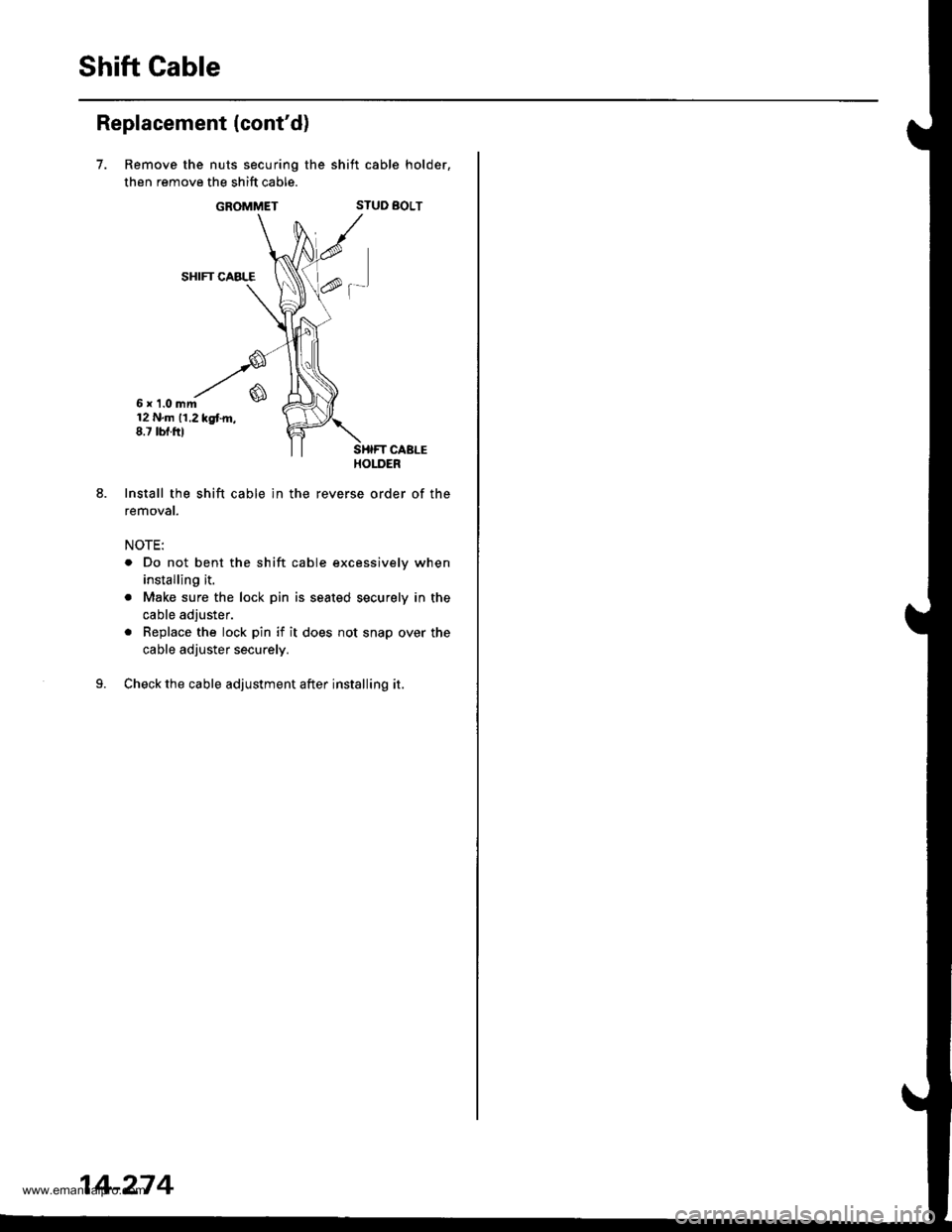
7.
6x 1.0mm12 N.m 11.2 kgtm,8.7 tbf.ftl
Install the shift cable ln the
removat.
NOTE:
Remove the nuts securing the shift cable holder,
then remove the shift cable.
GROMMETSTUD BOLT
SHIFT CABLE
f-'
. Do not bent the shift cable excessively when
installing it.
. Make sure the lock pin is seated securely in the
cable adjuster.
. Replace the lock pin if it does not snap over the
cable adjuster securely.
Check the cable adjustment after installing it.
14-274
www.emanualpro.com
Page 866 of 1395
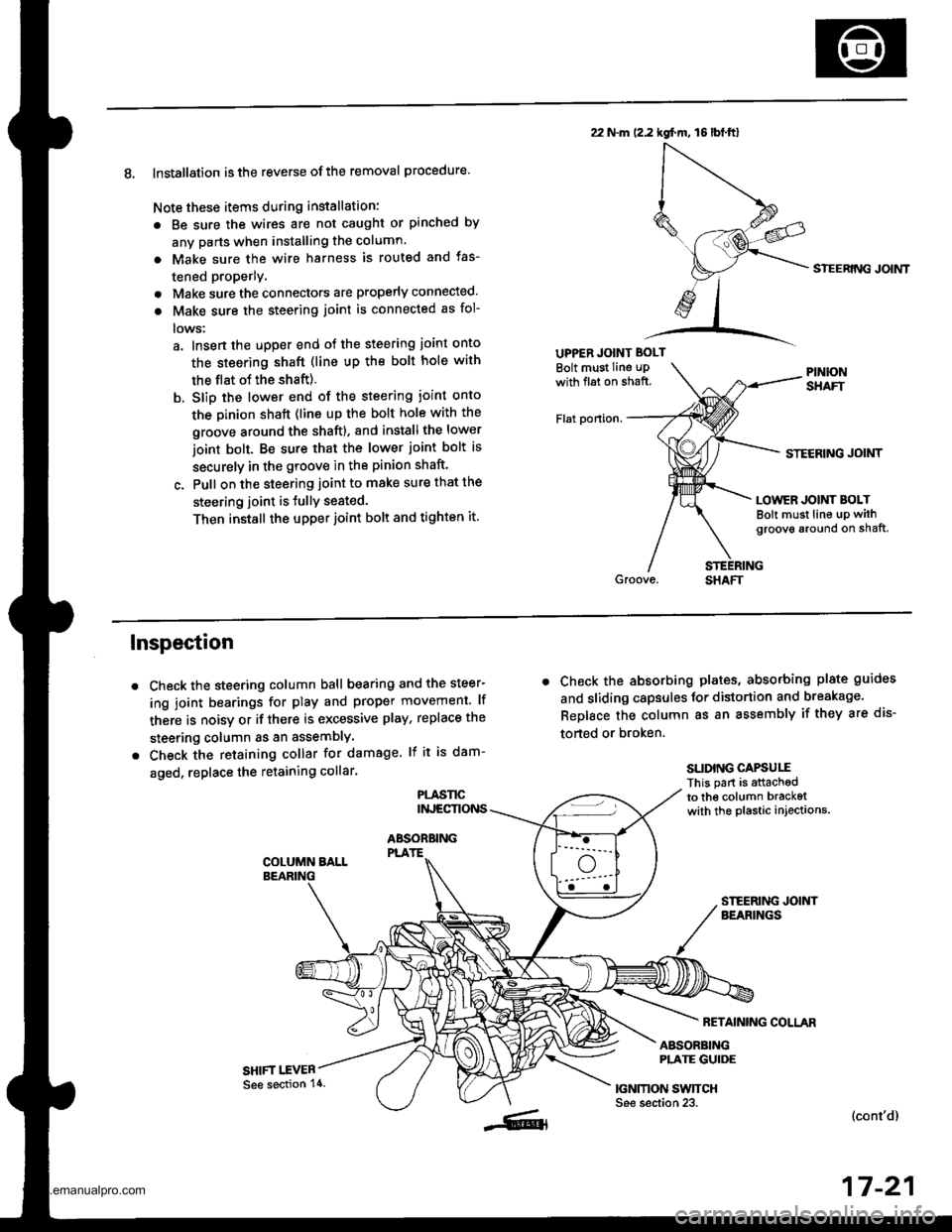
8. Installation is the reverse ofthe removal procedure.
Note these items during installation:
. Be sure the wires are not caught or pinched by
any parts when installing the column.
a Make sure the wire harness is routed and fas-
tened properly.
. Make sure the connectors are properly connected.
. Make sure the steering joint is connected as fol-
lows:
a. lnsert the uDper end of the steering joint onto
the steering shaft (line up the bolt hole with
the flat ot the shaft).
b. Slip the lower end of the steering ioint onto
the Dinion shaft (lins up the bolt hole with the
groove around the shaft). and installthe lower
ioint bolt. Be sure that the lower joint bolt is
securely in the groove in the pinion shaft'
c. Pull on the steering joint to make sure that the
steering joint is JullY seated.
Then install the upper joint bolt and tighten it.
22 N.m (2.2 kgf.m, 16lbt.ftl
UPPER JOINT BOLT
Bolt must Iine uPwith fl6t on shaft.
Flat ponion.
SIEERING JOIMT
STECRING JOINT
LOWER JOINT BOLTBolt must line up withgroove around on shaft,
Inspection
Check the steering column ball bearing and the steer-
ing joint bearings for play and proper movement. lf
there is noisy or if there is excessive play, replace the
steering column as an assemblY
Check the retaining collar for damage. lf it is dam-
aged, replace the retaining collar.
PLASl'tCINJECTIONS
ABSOBBINGPLATE
SHIFT I.EVER
. Check the absorbing plates, absorbing plate guides
and sliding capsules Jor distortion and breakage.
ReDlace the column as an assembly if they are dis-
torted or broken.
SLIDING CAPSUIIThis part is attachedto the column bracketwith the plastic injections.
FETAINING COLLAR
ABSORBINGPLATE GUIDE
|GNMON SWTTCHSee section 23.(cont'd)
17-21
See section 14.
www.emanualpro.com
Page 868 of 1395
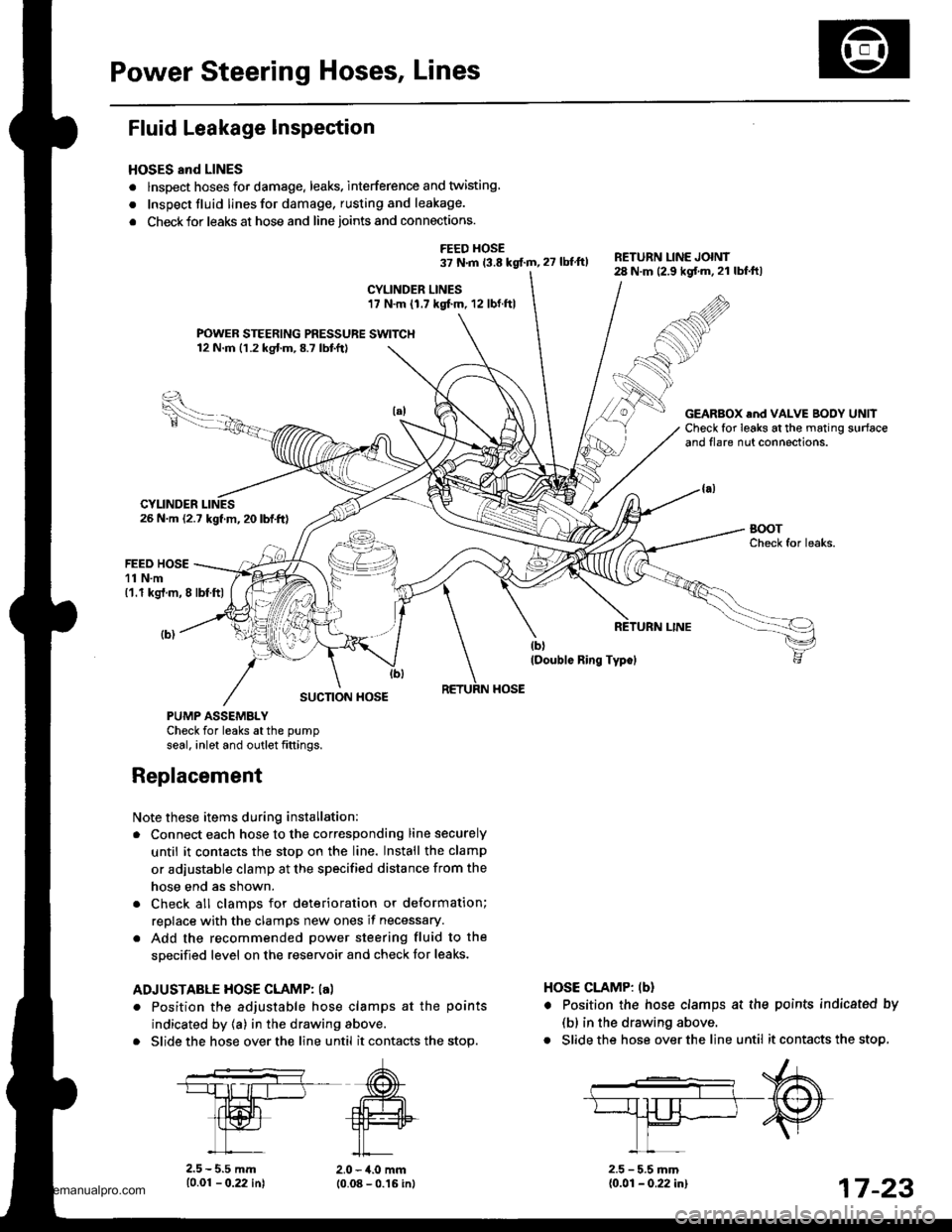
Power Steering Hoses, Lines
Fluid Leakage Inspection
HOSES and LINES
. lnspect hoses for damage. leaks. interference and twisting
. Inspect fluid linesfor damage, rusting and leakage.
. Check for leaks at hose and line joints and connections.
FEED HOSE37 N.m 13.8 kgf.m, 27 lbtft)RETURN LINE JOINT28 N.m (2.9 kgf.m.21 lbf.ftl
CYLINDER LINES17 N.m (1.7 kgf.m. 12 lbf.ftl
FOWER STEERING PRESSURE SWITCH12 N.m (1.2 kgf.m,8.7 lbtft)
26 N.m (2.7 kgf.m, 20 lbf.ft)
GEARBOX .nd VALVE BODY UNllCheck for leaks at the mating surfaceand flare nut connections.
CYLINDER
FEED HOSE11 N.m('1.1 kgt.m, 8 lbf.ftl
SUCTION HOSE
PUMP ASSEMBLYCheck for leaks atthe pump
seal. inlet and outlet fittings.
Note these items during installation:
. Connect each hose to the corresponding line securely
until it contacts the stop on the line. Install the clamp
or adjustable clamp at the specified distance from the
hose end as shown.
. Check all clamDs for deterioration or deformation;
replace with the clamps new ones if necessary.
. Add the recommended power steering fluid to the
specified level on the reservoir and check for leaks.
ADJUSTABLE HOSE CLAMP: la)
. Position the adjustable hose clamps at the points
indicated by (a) in the drawing above.
. Slide the hose over the line until it contacts the stop.
HOSE CLAMP: lbl
. Position the hose clamps at the
(b) in the drawing above.
. Slide the hose over the line until
Replacement
10.01 - 0.22 in)
points indicatsd by
it contacts the stop,
2.0 - 4.0 mm10.08 - 0.16 inl2.5 - 5.5 mm{0.01 - 0.22 in}17 -23
www.emanualpro.com
Page 869 of 1395
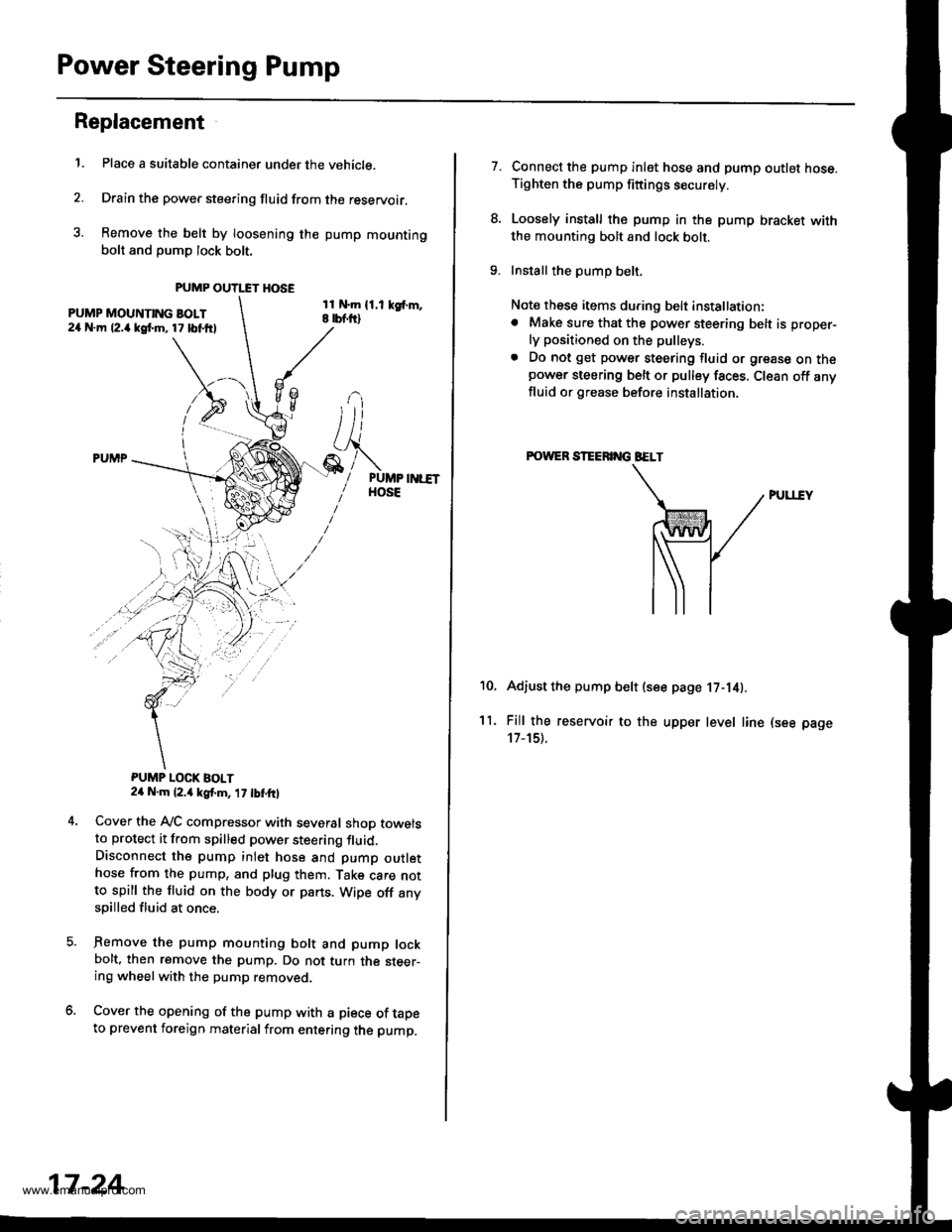
Power Steering Pump
Replacement
1.Place a suitable container under the vehicle.
Drain the power steering fluid from the reservoir.
Remove the belt by loosening the pump mountingbolt and pump lock bolt.
PUMP MOUNNNG BOI.T24 N.m 12.4 kgt m, 17 lbl.ftl
PUMP LOCK BOLT24 N.m (2.4 kg{.m, 1, tbfttl
Cover the IVC compressor with several shop towelsto protect it from spilled power steering fluid.Disconnect the pump inlet hose and pump outlethose from the pump, and plug them. Take care notto spill the lluid on the body or parts. Wipe off anyspilled fluid at once.
Remove the pump mounting bolt and pump lockbolt, then remove the pump. Do not turn the steer-ing wheelwith the pump removed.
Cover the opening of the pump with a piece of tapeto prevent foreign materialfrom entering the pump.
PUMP OU'I.TT HOSE
11 N.m (1.1 kgf.m,E rbf.ti)
17-24
7.Connect the pump inlet hose and pump outlet hose.Tighten the pump fittings securely.
Loosely install the pump in the pump bracket withthe mounting bolt and lock bolt.
Install the pump belt.
Note these items du.ing belt instsllation:. Make sure that the power steering belt is proper-
ly positioned on the pulleys.
. Do not get power steering fluid or grease on thepower steering belt or pulley faces, Clean off anyfluid or grease before installation
FOWER STEER G EELT
PUTrlY
Adiust the pump belt (see page 17-141.
Fill the reservoir to the upper level line (see page't7 -151..
10.
'l l.
www.emanualpro.com
Page 872 of 1395
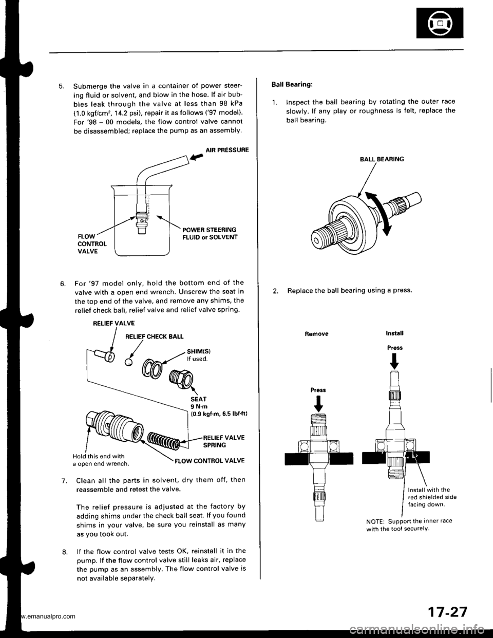
5. Submerge the valve in a container of power steer-
ing fluid or solvent, and blow in the hose. lf air bub-
bles leak through the valve at less than 98 kPa
(1.0 kgflcm'�, 14.2 psi), repair it as follows ('97 model).
For'98 - 00 models, the flow control valve cannot
be disassembled; replace the pump as an assembly
AIR PRESSURE
POWER STEENINGFLUID or SOLVENT
6.For'97 model only, hold the bottom end of the
valve with a open end wrench. Unscrew the seat in
the top end of the valve, and remove any shims, the
reliel check ball, relief valve and relief valve spring.
RELIEFALVE
RELIEF CHECK BALL
{w@r
7.
SEAT9 N.m(0.9 kgf.m, 6.5 lbfft)
RELIEF VALVESPRING
FLOW CONTBOL VALVE
Clean all the parts in solvent, dry them otf, then
reassemble and retest the valve.
The relief pressure is adjusted at the factory by
adding shims under the check ball seat lf you found
shims in your valve, be sure you reinstall as many
as you took out.
lf the flow control valve tests OK, reinstall it in the
pump. It the flow control valve still leaks air, replace
the pump as an assembly. The flow control valve is
not available separately.
8,
Hold this end witha open eno wrencn.
Ball Bearing:
'1. Inspect the ball bearing by rotating the outer race
slowly. lf any play or roughness is felt, replace the
ball bearing.
2. Replace the ball bearing using a press.
Removelnstall
Press
I
Press
I
lnstall with thered shaelded sidefacing down.
NOTEr SuPPort the inner race
with the tool securelY-
BALL EEARING
17-27
www.emanualpro.com
Page 882 of 1395
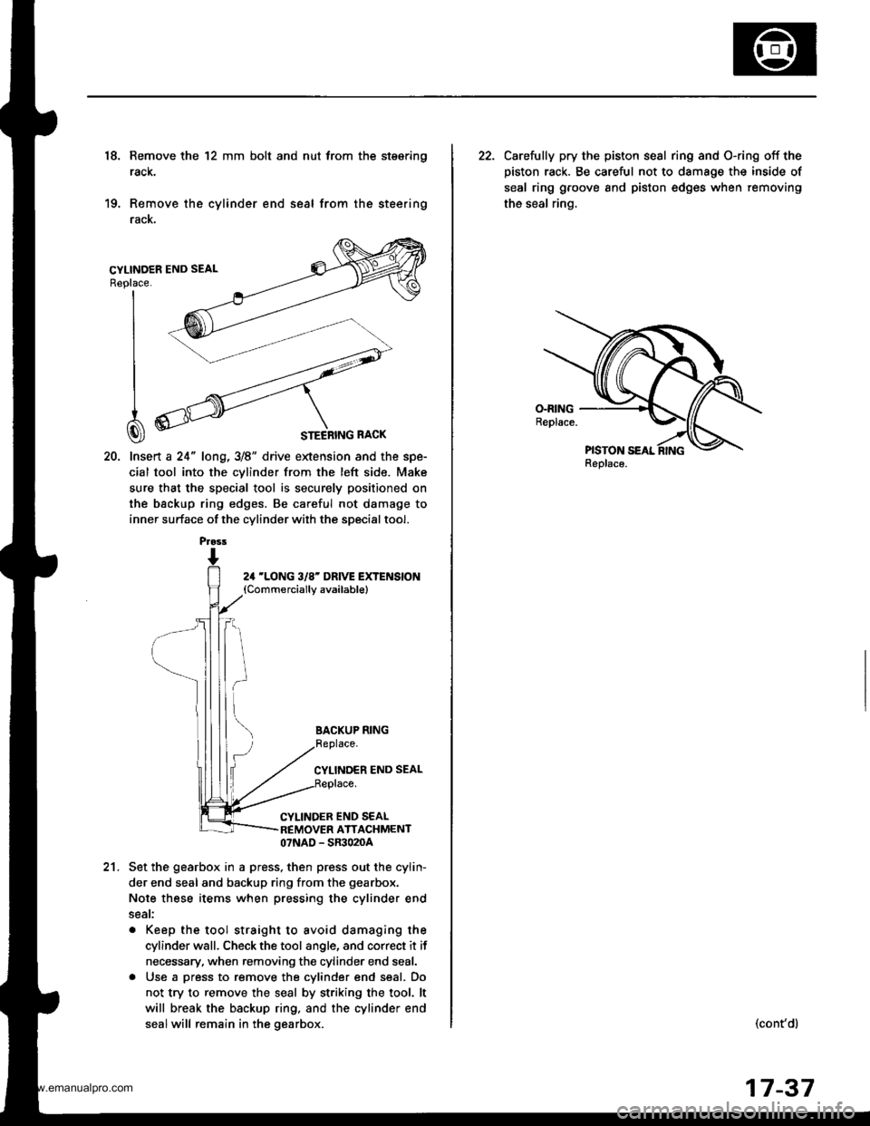
18. Remove the 12 mm bolt and nut trom the stsering
rack,
19. Remove the cylinder end seal from the steering
racK.
20. lnsert a 24" long,3/8" drive extension and the spe-
cial tool into the cvlinder from the left side. Make
sure that the special tool is securely positioned on
the backup ring edges. Be careful not damage to
inner surface of the cylinder with the special tool.
Replace.
I
I
I
CI
24 'LONG 3/8' DRIVE EXTENSION(Commerciallv available)
BACKUP RING
CYLINDER END SEAL
CYLINDER END SEALREMOVER ATTACHMENT07NAD - SR3020A
21.Set the gearbox in a press, then press out the cylin-
der end seal and backup ring from the gearbox.
Note these items when pressing the cylinder end
seat:
. Keep the tool straight to avoid damaging the
cylinder wall. Check the tool angle, and correct it if
necessary, when removing the cylinder end seal.
. Use a press to remove the cylinder end seal. Do
not try to remove the seal by striking the tool. lt
will break the backup ring, and the cylinder end
sealwill remain in the gearbox.
Prass
22. Carelully pry the piston sesl ring and O-ring off the
piston rack. Be careful not to damage the inside of
seal ring groove and piston edges when removing
the seal ring.
Replaco.
(cont'dl
17-37
www.emanualpro.com
Page 887 of 1395
Power Steering Gearbox
13.
Reassembly (cont'd)
Apply power steering fluid to the surface of the spe-
cial tool. Set the new seal rings over the special tool
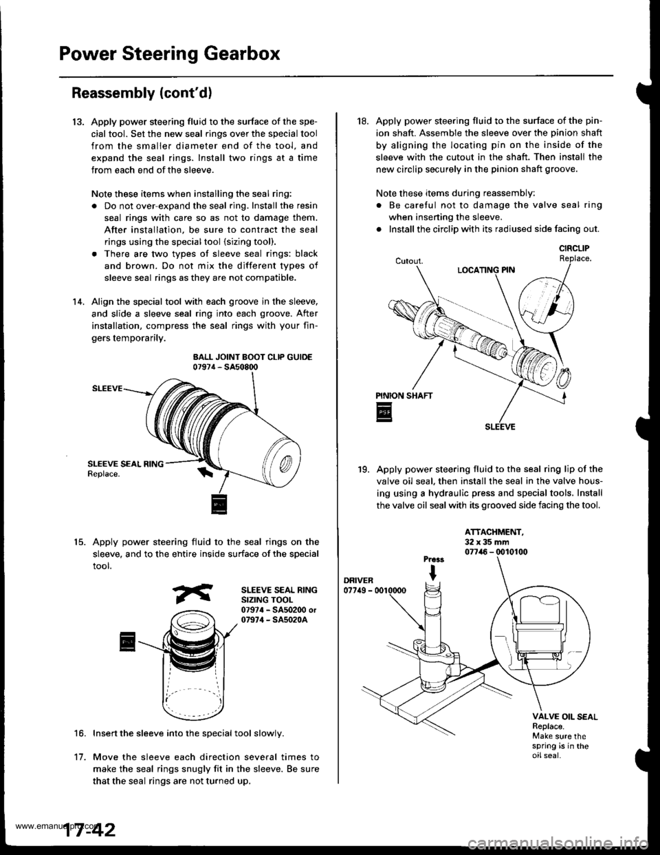
from the smaller diameter end of the tool. and
expand the seal rings. Install two rings at a time
Jrom each end ofthe sleeve.
Note these items when installing the seal ring:
. Do not over-expand the seal ring. Install the resin
seal rings with care so as not to damage them.
After installation, be sure to contract the seal
rings using the specialtool {sizing tool).
. There are two types of sleeve seal rings: black
and brown. Do not mix the different types of
sleeve seal rings as they are not compatible.
Align the special tool with each groove in the sleeve,
and slide a sleeve seal ring into each groove. After
installation, compress the seal rings with your fin-
gers temporarily.
BALL JOINT BOOT CLIP GUIDE07974 - SA508q)
SLEEVE
Apply power steering fluid to the seal rings on the
sleeve, and to the ehtire inside surface of the special
tool.
14.
15.
SLEEVE SEAL RINGSIZING TOOL07974 - SA502O0 or07974 - SA5020A
16.Insert the sleeve into the special tool slowly.
Move the sleeve each direction several times to
make the seal rings snugly fit in the sleeve. Be sure
that the seal rings are not turned up,
't1.
18. Apply power steering fluid to the surface of the pin-
ion shaft. Assemble the sleeve over the Dinion shaft
by aligning the locating pin on the inside of the
sleeve with the cutout in the shaft. Then install the
new circlip securely in the pinion shaft groove.
Note these items during reassembly:
. Be caretul not to damage the valve seal ring
when inserting the sleeve.
. Install the circlip with its radiused side facing out.
Apply power steering fluid to the seal ring lip of the
valve oil seal. then install the seal in the valve hous-
ing using a hydraulic press and special tools. Install
the valve oil seal with its grooved side facing the tool.
19.
ATTACHMENT,32x35mm077i16 - (x)10100
VALVE OIL SEALReplace.Make sure thespring is in theoilseal.
CIRCLIP
www.emanualpro.com