ECU HONDA CR-V 1998 RD1-RD3 / 1.G Service Manual
[x] Cancel search | Manufacturer: HONDA, Model Year: 1998, Model line: CR-V, Model: HONDA CR-V 1998 RD1-RD3 / 1.GPages: 1395, PDF Size: 35.62 MB
Page 752 of 1395
Transfer Assembly
Disassembly (cont'd)
7.
Secure the transfer housing in a bench vise withsoft iaws. To prevent damage to the transfer hous-ing, always use soft jaws or equivalent materials
between the transfer housing and the vise.
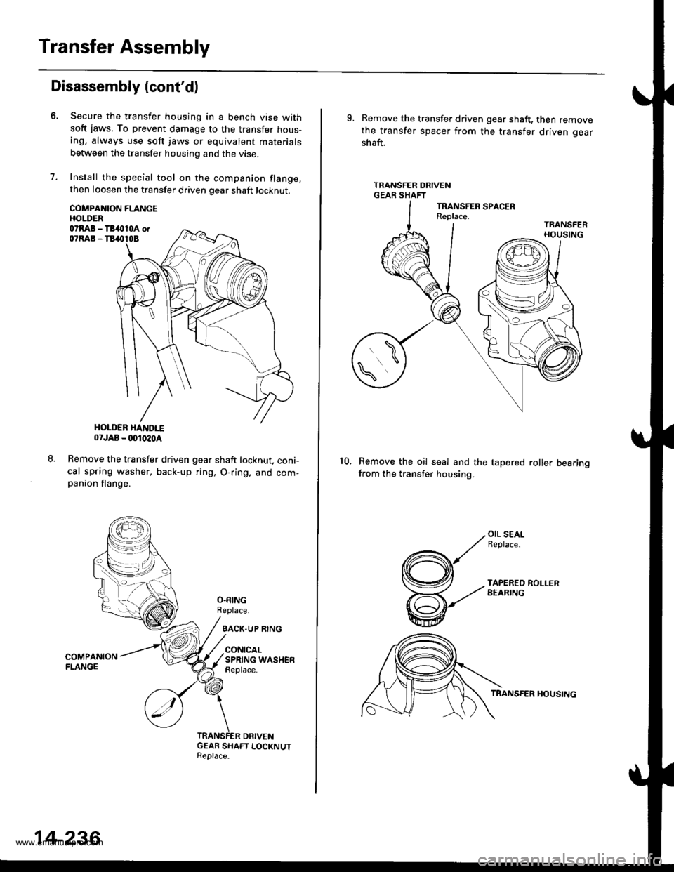
Install the special tool on the companion flange,then loosen the transfer driven gear shaft locknut.
COMPANION FLANGEHOI.DER07RAB - TB4lll0A orOTRAB - TB&TOB
HOLDER HAITDI..E07JAB _ (x)1020a
Remove the transfer driven gear shaft locknut, coni-cal spring washer, back-up ring, O-ring. and com-panion flange.
O.RINGReplace.
BACK-UP RING
CONICALSPRING WASHENReplace.
GEAR SHAFT LOCKNUTReplace.
14-236
9. Remove the transfer driven gear shaft, then removethe transfer spacer from the transfer driven gear
shaft.
TRANSFER DRIVENGEAR SHAFT
Remove the oil seal and the tapered roller bearingfrom the transfer housing.
10.
OIL SEALFeplace-
TAPEREO ROLLERBEARING
TRANSFER HOUSING
www.emanualpro.com
Page 758 of 1395
Transfer Assembly
Reassembly (cont'd)
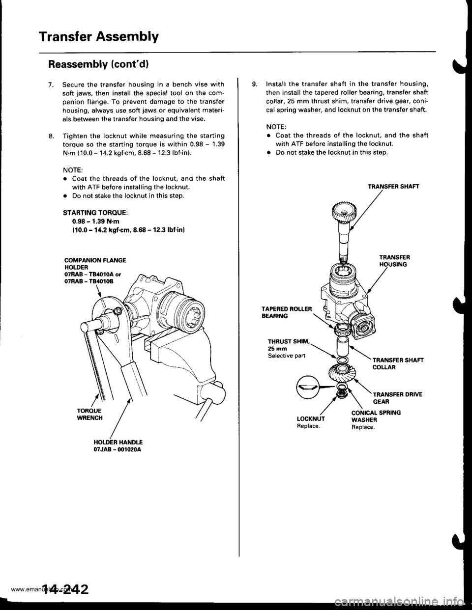
7.Secure the transfer housing in a bench vise with
soft jaws, then install the special tool on the com-
panion flange. To prevent damage to the transfer
housing, always use soft jaws or equivalent materi-
als between the transfer housing and the vise.
Tighten the locknut while measuring the starting
torque so the starting torque is within 0.98 - '1.39
N.m (10.0 - 14.2 kgf.cm, 8.68 - 12.3 lbnin).
NOTE:
Coat the threads of the locknut, and the shaft
with ATF before installing the locknut.
Do not stake the locknut in this step.
STARTING TOROUE:
0.98 - 1.39 N.m
{10.0 - 14.2 kgrf.cm,8.68 - 12.3 lbf'inl
COMPANION FLANGEHOLDER
07JAB - @1020A
14-242
9. Install the transfer shaft in the transfer housing,
then install the tapered roller bearing, transfer shaft
collar.25 mm thrust shim, transfer drive gear, coni-
cal spring washer, and locknut on the transfer shaft.
NOTE:
. Coat the threads of the locknut. and the shaft
with ATF before installing the locknut.
. Do not stake the locknut in this step.
TRANSFER
THRUST SXIM,25 mmSelective pan
TRANSFER DRIVEGEAR
CONICAL SPRINGWASHERReplace.
www.emanualpro.com
Page 759 of 1395
10.
11.
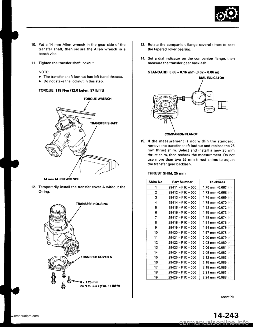
Put a 14 mm Allen wrench in the gear side of the
transfer shaft, then secure the Allen wrench in a
bench vise.
Tighten the transfer shaft locknut.
NOTE:
. The transfer shaft locknut has left-hand threads.
. Do not stake the locknut in this step.
TOROUE: 118 N'm 112.0 kgf.m, 87 lbf.ftl
Temporarily install the transfer cover A without
O-ring.
TRANSFER HOUSING
TRANSFER COVER A
the12.
g/FrE24 N.m 12.4 kgt.m, 17 lbf.ftl
TOROUE WRENCH
tt el
g 9-r'r.ru--g 24 N.m 12.4 |
14-243
13.
14.
Rotate the companion flange several times to seat
the tapered roller bearing.
Set a dial indicator on the companion flange, then
measure the transfer gear backlash.
STANDARD: 0.06 - 0.16 mm {0.02 - 0.06 inl
COMPANION FLANGE
lf the measurement is not within the standard.
remove the transfer shaft locknut and replace the 25
mm thrust shim. Select and install a new 25 mm
thrust shim. then recheck the measurement. Do not
use more than two 25 mm thrust shims to adiust
the transfer gear backlash.
THRUST SHIM, 25 mm
(cont'd)
15.
DIAL INOICATOR
Shim No.Part NumborThickness
I29411-P1C-0001.70 mm (0.067 in)
229412-P1C-0001.73 mm (0.068 in)
29413-P1C-0001.76 mm (0.069 in)
429414-P1C-0001.79 mm (0.070 in)
29415-PlC-0001.82 mm (0.072 in)
629416-P1C-0001.85 mm (0.073 ini
729417-PlC-0001.88 mm (0.074 in)
d29418-P1C-0001.91 mm {0.075 in)
29419-P1C-0001.94 mm (0.076 in)
1029420-PtC-0001.97 mm (0.078 in)
1129421 - P1C - 0002.00 mm (0.079 in)
29422-P1C-0002.03 mm 10.080 in)
29423-P'1C-0002.06 mm (0.081 in)
1429424-P1C-0002.09 mm 10.082 in)
29425-P1C-0002.12 mm (0.083 in)
1629426-P1C-0002.'15 mm (0.085 in)
1729427 - P1C -O002.18 mm (0.086 in)
1829428-PlC-0002.21 mm (0.087 in)
1929429-P1C-0002.24 mm {0.088 in)
www.emanualpro.com
Page 761 of 1395
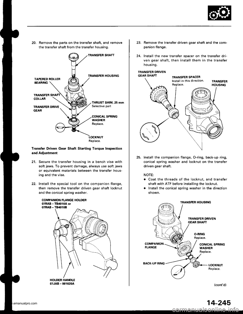
20. Remove the parts on the transfer shaft, and remove
the transfer shaft from the transfer housinq.
TRANSFER SHAFT
TRANSFER HOUSINGTAPEFED ROLLERBEARNG
TRANSFERCOLLAR
TRANSFER DRIVEGEAR
THRUST SHIM, 25 mmSelective pan
CONICAL SPRINGWASHERReplace.
Transf€r Driven Gear Shaft Starting Torque Inspsction
and Adjustment
21. Secure the transfer housing in a bench vise with
soft jaws, To prevent damage, always use soft jaws
or equivalent materials between the transfer hous-
ing and the vise.
22. Install the special tool on the companion flange,
then remove the transfer driven oear shaft locknut
and the conical spring washer.
COMPANION FLANGE HOLDER07RAB - TB,010A ol07RAB - TB,010B
Replace.
23. Remove the transter driven gear shaft and the com-
panion flange,
24. Install the new transfer spacer on the transfer dri-
ven gear shaft, then install them in the transfer
housrng.
TRANSFER DRIVENGEAR SHAFTTFANSFER SPACERlnstall in this direction.Replace.
25.Install the companion flange, O-ring, back-up ring.
conical spring washer and locknut on the transfer
driven gear shaft.
NOTE:
. Coat the threads of the locknut, and transfer
shaft with ATF before installing the locknut.
. Install the conical spring washer in the direction
shown,
TRANSFER HOUSING
O.RINGReplace.
CONICAL SPRINGWASHERReplace.
LOCKNUTReplace.
(cont'd)
BACK.UP RING
14-245
www.emanualpro.com
Page 762 of 1395
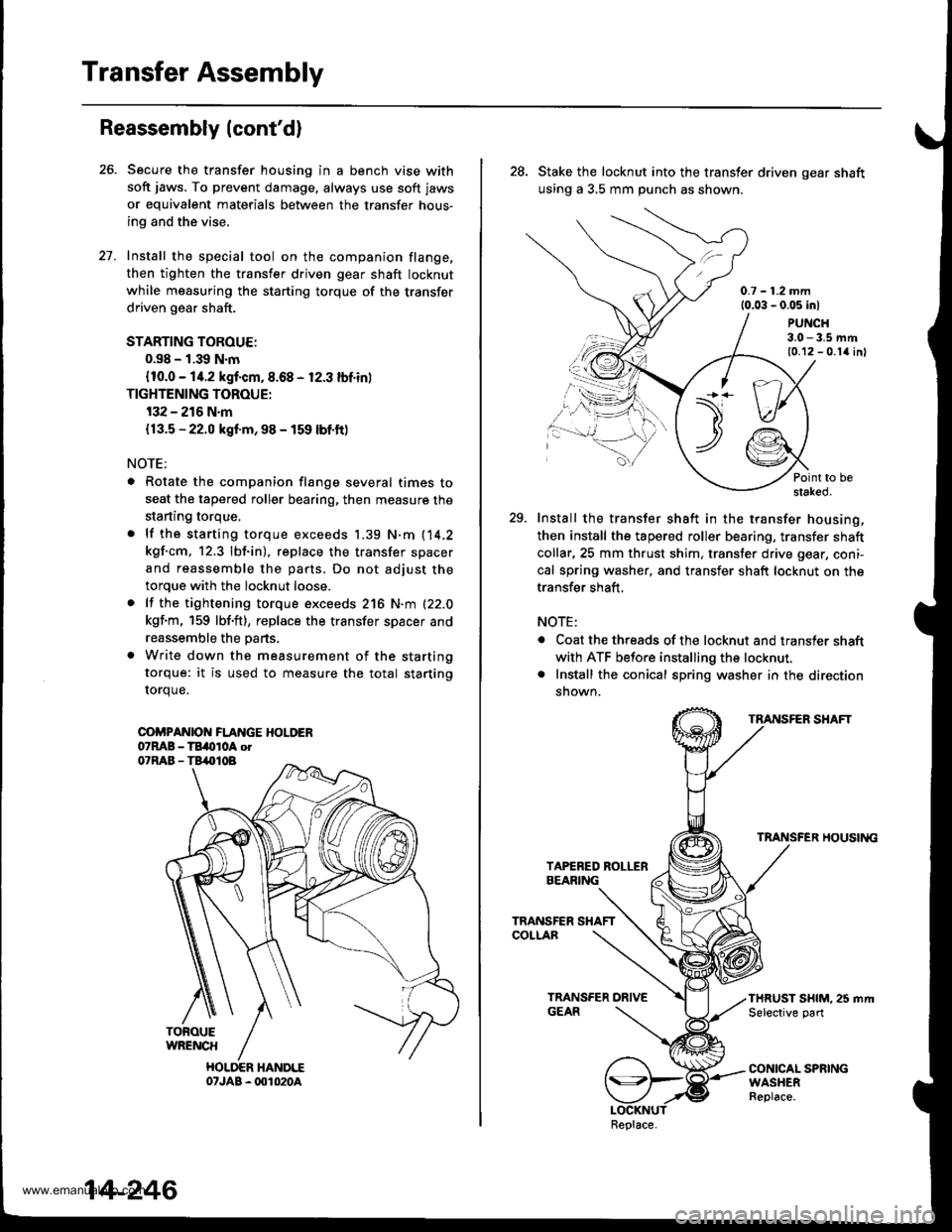
Transfer Assembly
Reassembly (cont'd)
Secure the transfer housing in a bench vise with
soft jaws. To prevent damage, always use soft jaws
or equivalent materials between the transfer hous-
ing and the vise.
Install the special tool on the companion flange,
then tighten the transfer driven gear shaft locknut
while measuring the starting torque of the transfer
driven gear shaft.
STARTING TOROUE:
0.s8 - 1.39 N.m
{10.0 - 14.2 kgf.cm,8.68 - 12.3 lbf.in)
TIGHTENING TOROUE:
132 - 216 N.m
{13.5 - 22.0 kgf.m, 98 - 159 lbf.ft)
NOTE;
. Rotate the companion flange several times to
seat the tapered roller bearing, then measure the
starting torque,
. lf the starting torque exceeds 1.39 N.m (14,2
kgf.cm, 12.3 lbf.in), replace the transfer spacer
and reassemble the parts. Do not adjust the
torque with the locknut loose.
. lf the tightening torque exceeds 216 N.m (22.0
kgf.m, 159 lbf'ft), replace the transfer spacer and
reassemble the parts.
. Write down the measurement of the starting
torque: it is used to measure the total starting
rorque.
COi'PANIOI{ FLANGE HOLDER07MB - TBi(tloA otO'RAB - TB,.|}IOB
TOFOUEWRENCH
HOLDER HANDLE07JAB - 001020A
27.
14-246
28. Stake the locknut into the transfer driven gear shaft
using a 3,5 mm punch as shown.
0.7 - 1.2 mm{0.03 - 0.05 inl
PUNCH3.0 - 3.5 mm10.12 - 0.1{ inl
Point to bestaked.
29. Install the transfer shaft in the transfer housing,
then install the tapered roller bearing, transfer shaft
collar,25 mm thrust shim, transter drive gear, coni-
cal spring washer, and transfer shaft locknut on the
transfer shaft,
NOTE:
. Coat the threads of the locknut and transler shaft
with ATF before installing the locknut.. Install the conical spring washer in the direction
snown.
TRANSFER SHAFT
TRANSFER HOUSII{G
THRUST SHIM. 25 mrt|Selective part
CONICAL SPRINGWASHERReplace.
\t)t--/./
.,.-,.,\
Replace.
www.emanualpro.com
Page 763 of 1395
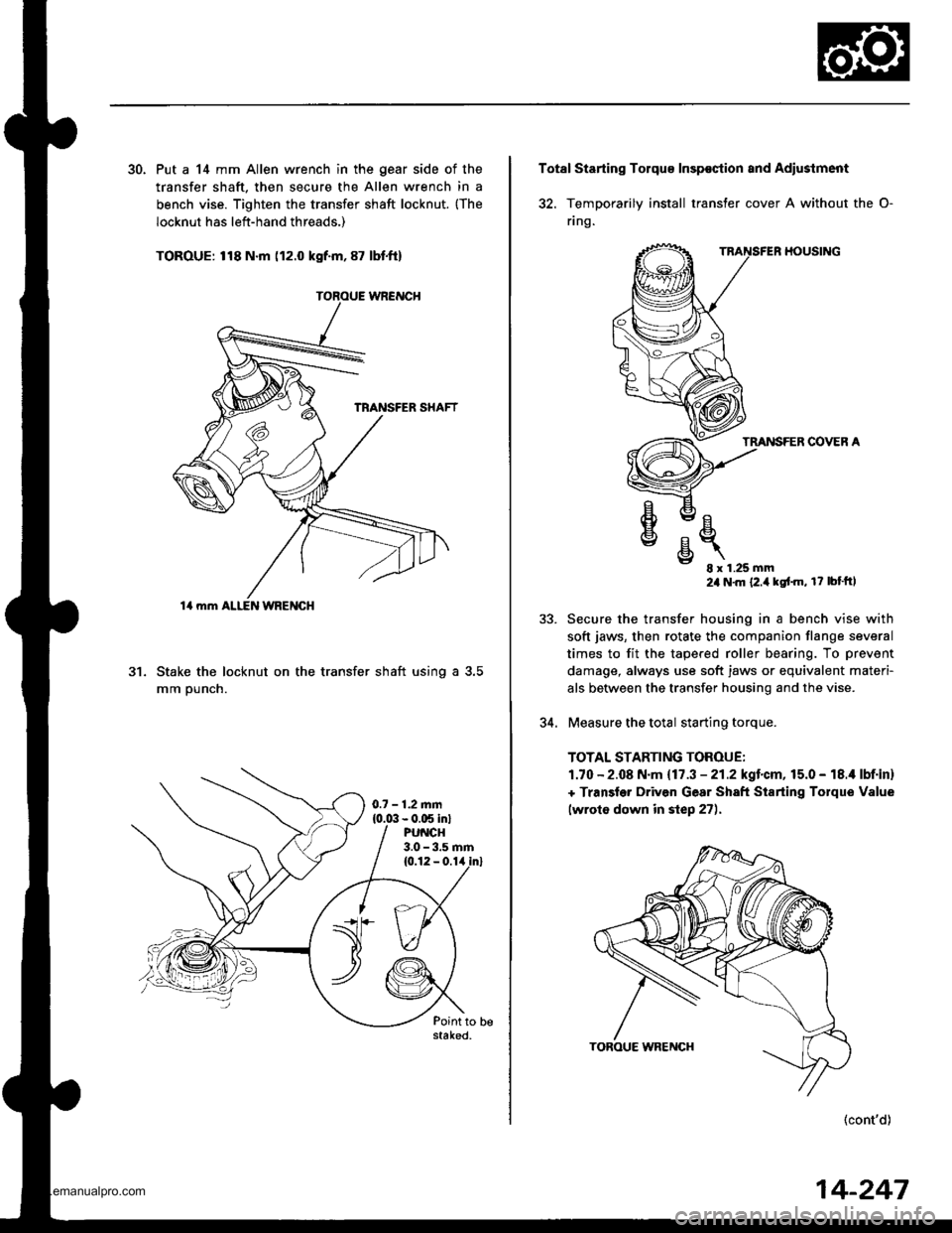
30. Put a 14 mm Allen wrench in the gear side of the
transfer shaft. then secure the Allen wrench in a
bench vise. Tighten the transfer shaft locknut. {The
locknut has left-hand threads,)
TOROUE: 118 N.m (12.0 kgf.m, 87 lbt.ft)
Stake the locknut on the transfer shaft using a 3.5
mm ounch.
al
14 mm ALI-EN WRENGH
0.7 - 1.2.nm{0.0:1- 0.C5 in}PU CH3.0 - 3.5 rnm
Total Starting Tolqu€ Insp€ction and Adiustment
32. TemDorarilv install transter cover A without the O-
flng.
HOUSING
TMNSFER COVER A
e
€
v
E- 8x1.25mm24 N'm {2.i1kgt'm, r? bt'ftl
Secure the transfer housing in a bench vise with
soft jaws, then rotate the companion flange several
times to fit the tapered roller bearing. To prevent
damage, always use soft jaws or equivalent materi-
als betlveen the transfer housing and the vise.
Measure the total starting torque.
TOTAL STARTING TOROUE:
1.70 - 2.08 N.m {17.3 - 21.2kgl.cm,15.0 - 18.i1 lbf.in}
+ Transler Driven Gear Sh8ft Starting Torque Value
lwroto down in step 27).
(cont'd)
5J.
34.
14-247
www.emanualpro.com
Page 777 of 1395
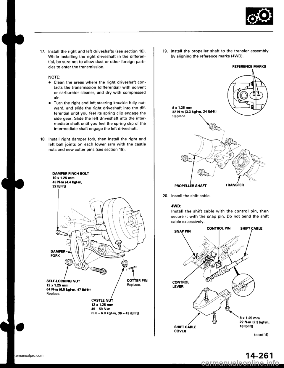
17. Install the right and left driveshafts (see section 18).
While installing the right driveshaft in the differen-
tial, be sure not to allow dust or other foreign parti-
cles to enter the transmission.
NOTE:
. Clean the areas where the right driveshaft con-
tacts the transmission (differential) with solvent
or carburetor cleaner, and dry with compressed
air.
. Turn the right and left steering knuckle fully out-
ward, and slide the right driveshaft into the dif-
ferential until you feel its spring clip engage the
side gear. Slide the left driveshaft into the inter-
mediate shaft until you feel the spring clip of the
intermediate shaft engage the left driveshaft,
18. Install right damper fork, then install the right and
left ball joints on each lower arm with the castle
nuts and new cotter pins (see section 18).
DAMPER PINCH BOLT10 x 1 .25 mm43 N.m 14.{ kgf.m,32 rbr.ftl
DAMPERFORX
SELF.LOCKING NUT12 x 1,25 mm6/t N m (6.5 kg{.m, a7 lbtft)Replace.
Replace.
CASTLE12 x 1.25 mm49 - 59 N.m15.0 - 6.0 kgl m, 36 - {3 lbtftl
19, Install the propeller shaft to the transfer assembly
by aligning the reference marks (4WD).
20.
8 x 1.25 mm32 N.m (3.3 kgt'm,2ir blft)
Feplace.
\
@_
PROPELLER SHAFT
lnstall the shift cable.
4WD:
Install the shift cable with the control pin, then
secure it with the snap Din. Do not bend the shift
cable excessivelv.
CONTROLLEVER
SHIFT CAALECOVER
8 x 1.25 mm22 N.m 12.2l'gl m,16 rbt.ftl
(cont'd)
REFERENCE MARKS
14-261
www.emanualpro.com
Page 780 of 1395
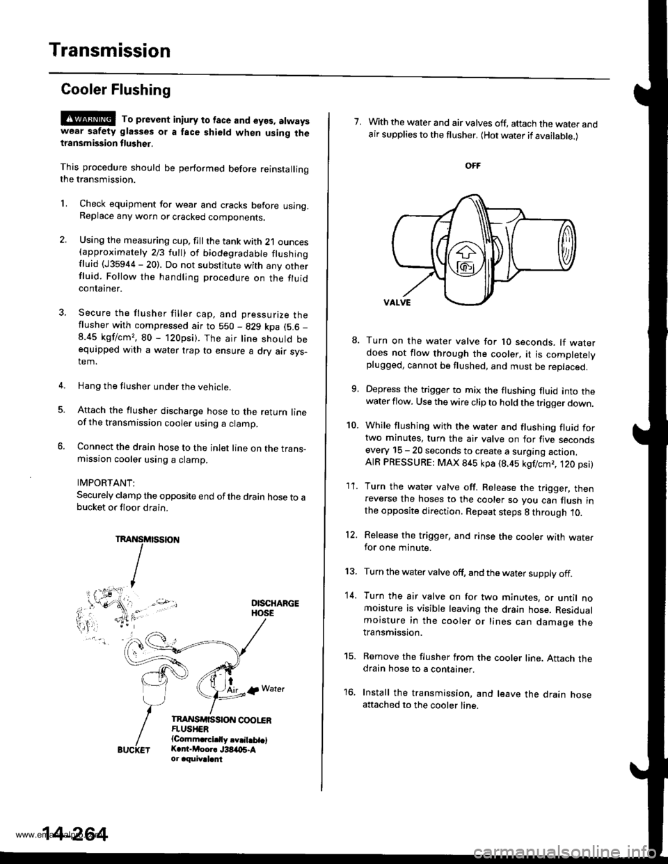
Transmission
Cooler Flushing
@@ To prevent in;ury to face and eyos, atwayswear safety glasses ot a face shield when using thetlansmission flusher.
This procedure should be performed before reinstallingthe transmission.
2.
LCheck equipment for wear and cracks before using.Replace any worn or cracked components.
Using the measuring cup. fill the tank with 21 ounces{approximately 213 lull) ol biodegradable flushingfluid (J35944 - 20). Do not substitute with any otherfluid. Follow the handling procedure on the fluidcontaaner.
Secure the flusher filler cap, and pressurize theflusher with compressed air to 550 - 829 kpa (5.6 _
8.45 kgf/cm,, 80 - 120psi). The air line should beequipped with a water trap to ensure a dry air sys-tem.
Hang the flusher under the vehicle.
Attach the flusher discharge hose to the return lineof the transmission cooler using a clamp.
Connect the drain hose to the inlet line on the trans-mission cooler using a clamp.
IMPORTANT:
Securely clamp the opposite end ofthe drain hose to abucket or floor drain.
DISCHARGEHOSE
tAirlp Water
TnAI{SrfiSStoN coot"€RFLUSHER{Comm.rcidly.v.il.bt.lK.r -Moor. J38,t{15.Aor aquival.nt
5.
14-264
7. With the water and air valves off, attach the water andair supplies to the flusher. (Hot water if available.)
10.
8.
1'�I.
Turn on the water valve for 1O seconds. lf waterdoes not flow through the cooler, it is completelyplugged, cannot be flushed, and must be replaced.
Depress the trigger to mix the flushing fluid into thewater flow. Use the wire clip to hold the trigger down.
While flushing with the water and flushing fluid fortwo minutes, turn the air valve on for five secondsevery 15 - 20 seconds to create a surging action.AIR PRESSURE: MAX 845 kpa (8.45 kgf/cmr, t20 psi)
Turn the water valve off. Release the trigger, thenreverse the hoses to the cooler so you can flush inthe opposite direction. Repeat steps 8 through 10.
Release the trigger, and rinse the cooler with wate.for one minute.
Turn the water valve off, and the water supply off.
Turn the air valve on for two minutes, or until nomoisture is visible leaving the drain hose. Residualmoisture in the cooler or lines can damage thetransmission.
Remove the flusher from the cooler line. Attach thedrain hose to a container.
Install the transmission, and leave the drain hoseattached to the cooler line.
12.
13.
14.
to.
www.emanualpro.com
Page 782 of 1395
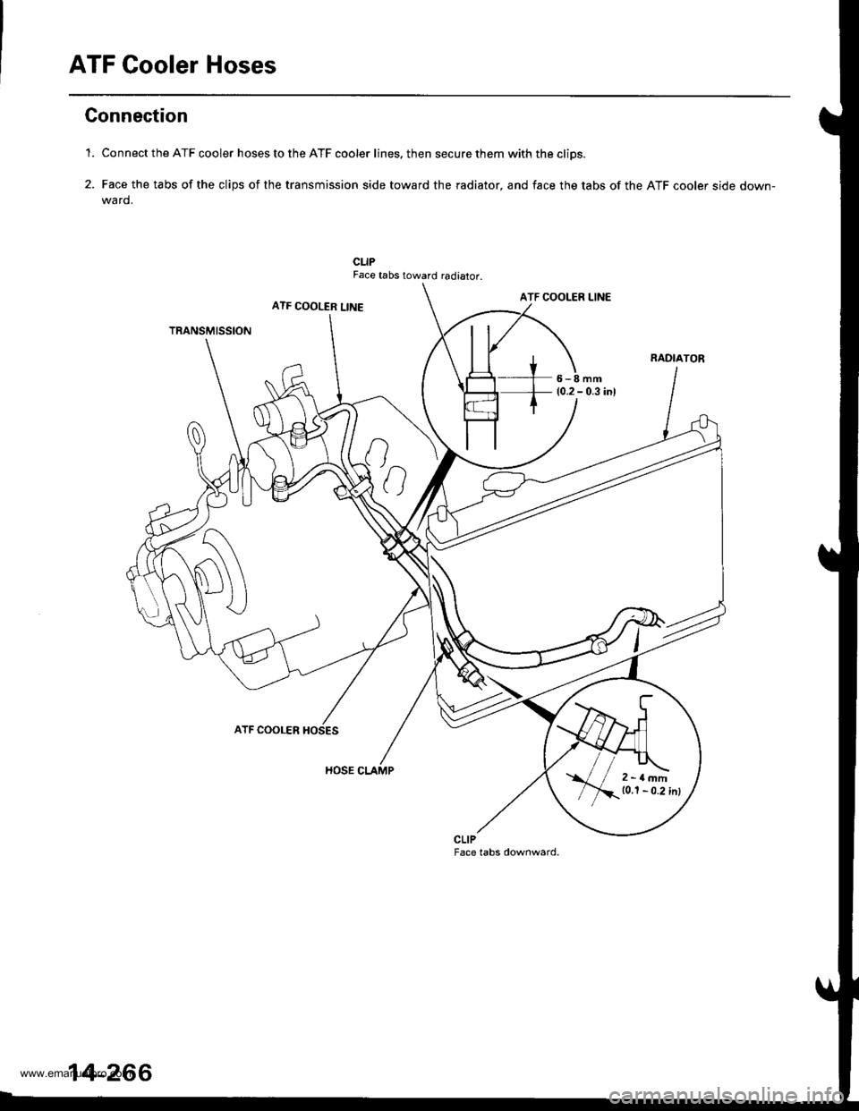
ATF Cooler Hoses
Gonnection
'1. Connect the ATF cooler hoses to the ATF cooler lines. then secure them with the cliDs.
2. Face the tabs of the clips of the transmission side toward the radiator, and face the tabs of the ATF cooler side down-wa rd.
CLIPFace tabs toward radiator.
ATF COOLER LINEATF COOLER LINE
TRANSMISSION
6-8mm(0.2 - 0.3 inl
ATF COOLER
HOSE CLAMP
CLIPFace tabs downward.
2-rlmm10.1 - 0.2 inl
14-266
www.emanualpro.com
Page 783 of 1395
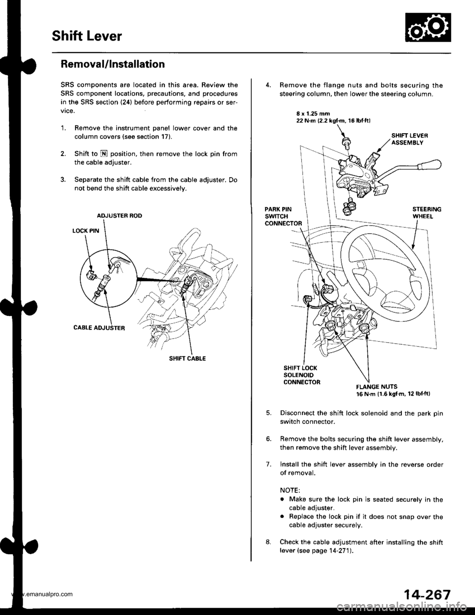
Shift Lever
Removal/lnstallation
SRS components are located in this area. Review the
SRS component locations, precautions, and procedures
in the SRS section (24) before performing repairs or ser-
vrce.
1. Remove the instrument panel lower cover and the
column covers (see section 171.
2. Shift to N position, then remove the lock pin from
the cable adjuster.
3. Separate the shift cable from the cable adjuster, Do
not bend the shift cable excessively.
ADJUSTER ROD
SHIFT CABLE
22 N.m (2.2 kgf.m, 16 lbt.ftl
7.
Remove the flange nuts and bolts securing the
steering column, then lower the steering column.
FLANGE NUTS16 N m (1.6 kgl m, 12 lbt'ftl
Disconnect the shift lock solenoid and the park pin
switch connector.
Remove the bolts securing the shift lever assembly,
then remove the shift lever assembly.
lnstall the shift lever assembly in the reverse order
of removal.
NOTE;
. Make sure the lock pin is seated securely in the
cable adjuster.
. Replace the lock pin if it does not snap over the
cable adjuster securely.
Check the cable adjustment after installing the shift
lever (see page 14-27'l).
14-267
www.emanualpro.com