end HONDA CR-V 1998 RD1-RD3 / 1.G Repair Manual
[x] Cancel search | Manufacturer: HONDA, Model Year: 1998, Model line: CR-V, Model: HONDA CR-V 1998 RD1-RD3 / 1.GPages: 1395, PDF Size: 35.62 MB
Page 194 of 1395
Radiator
Engine Coolant Refilling and Bleeding (cont'dl
Mix the recommended antifreeze with an equal
amount of water in a clean container.
NOTE:
. Always use Genuine Honda Antifreeze/Coolant.
Using a non-Honda coolant can result in corro-s\on, ca
sng t\e coo\
g sys\em \o ma\lunct\on
o. fail.
For best corrosion protection, the coolant con-
centration must be maintained year-round at50% minimum. Coolant concentrations less than
50% may not provide sufficient protection against
corrosion or freezing. Coolant concentrationsgreater than 60% will impair cooling efficiency
and are not recommended.
Do not use additional rust inhibitors or anti-rustproducts; they may not be compatible with the
coolant.
Engine Coolant Refill Capacity Iincluding 0.6 / 10.63US $, 0.53 lmp qtl for hoater and ressrvoirl:
A/T: 3.9 f {4.1 US $, 3.4 lmp qtl
M/T: 1.O t 14.2 US $, 3.5 lmp qrl
10-6
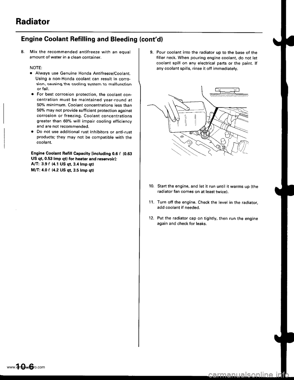
9. Pour coolant into the radiator uD to the base of the
filler neck. When pouring engine coolant. do not let
coolant spill on any electrical pans or the paint. lf
any coolant spills, rinse it oft immediately.
Start the engine, and let it run until it warms up (the
radiator fan comes on at least twice).
Turn off the engine. Check the level in the radiator,
add coolant if needed.
Put the radiator cap on tightly. then run the engine
again and check for leaks.
11.
10.
12.
www.emanualpro.com
Page 197 of 1395
Testing
Replace the thermostat if it is open at room temperature.
To test a closed thermostat:
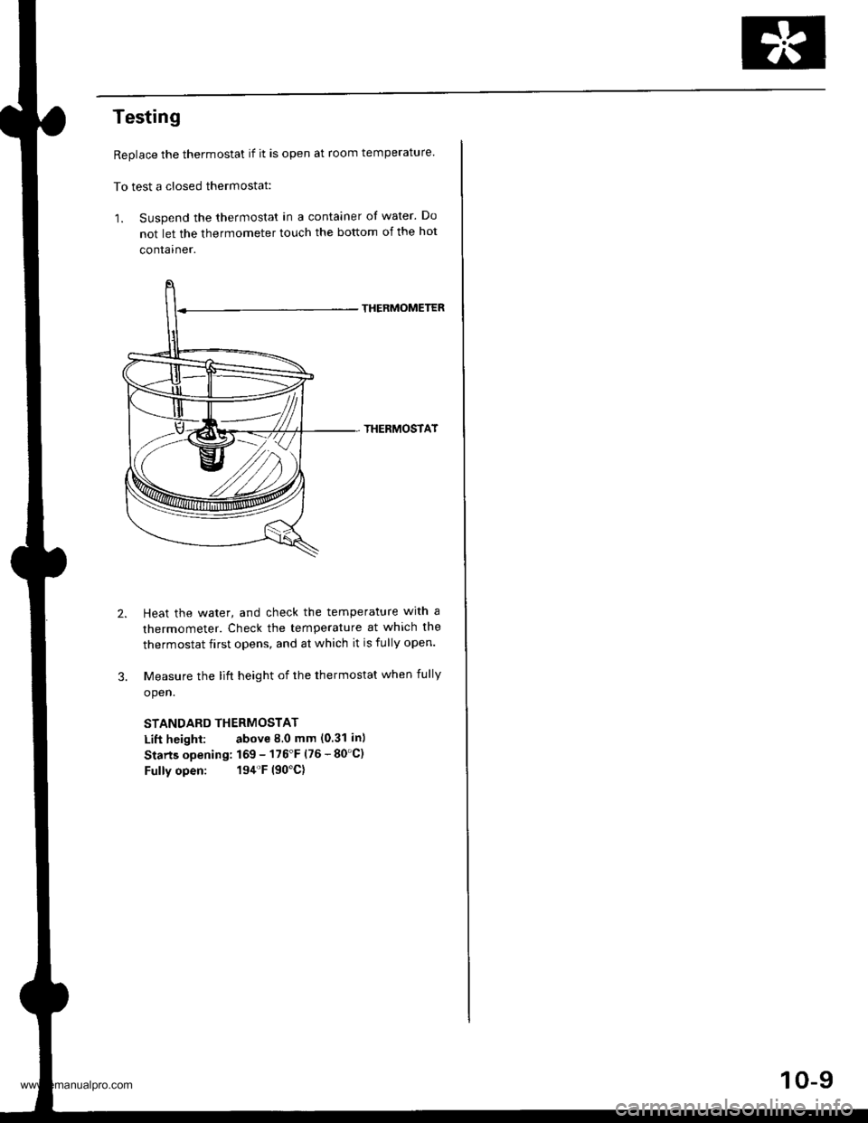
1. Suspend the thermostat in a container of water. Do
not let the thermometer touch the bottom of the hot
container.
THERMOMETER
THERMOSTAT
Heat the water, and check the temperature with a
thermometer. Check the temperature at which the
thermostat first opens, and at which it is fully open.
Measure the lift height of the thermostat when fully
open.
STANDARD THERMOSTAT
Lift height: above 8.0 mm (0.31 in)
Starts opening: 169 - 176'F (76 - 80'C)
Fully open: 194'F (90'C)
10-9
www.emanualpro.com
Page 202 of 1395
Fan Control
Fan Motor Testing
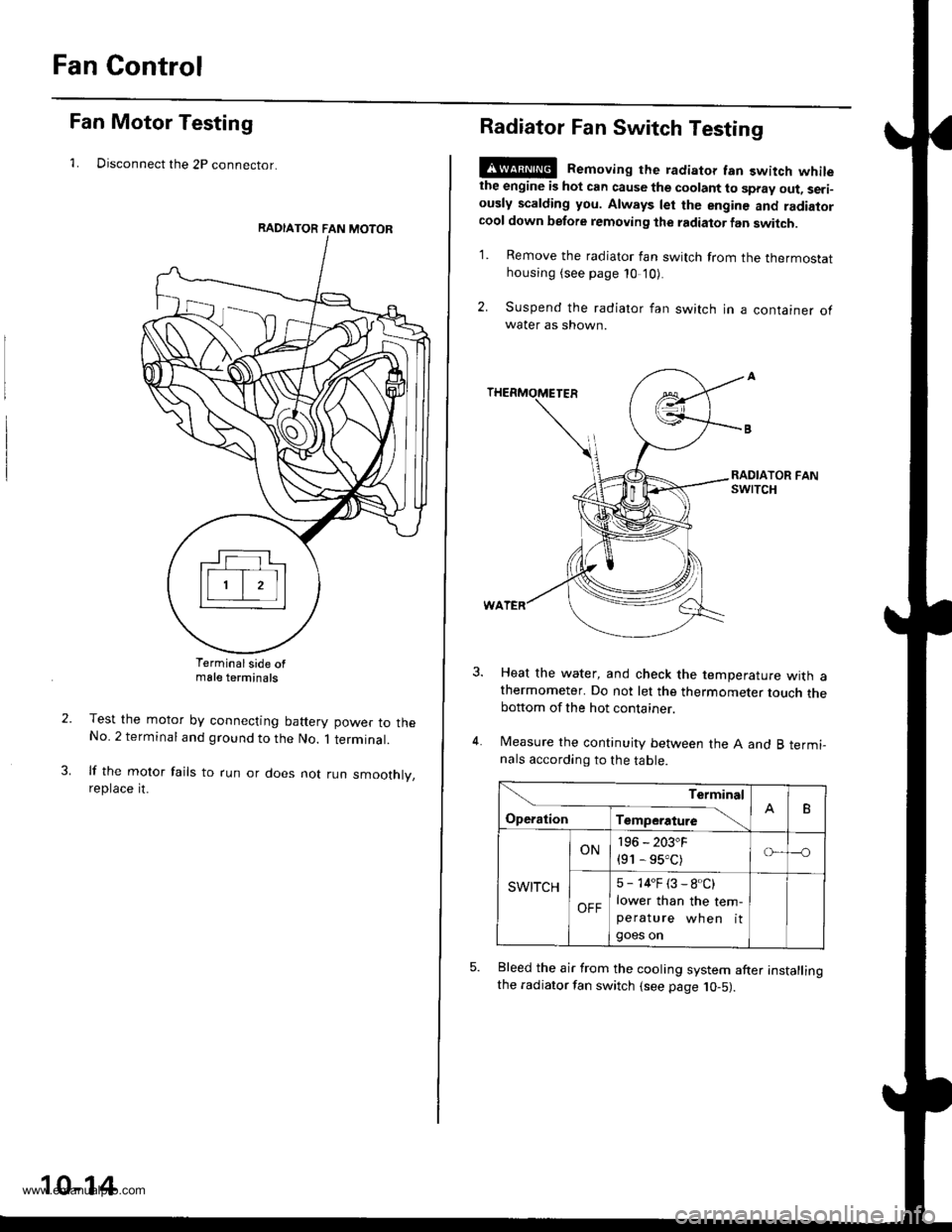
1. Disconnect the 2P connector.
Terminalside ofmale terminals
Test the motor by connecting battery power to theNo. 2 terminal and ground to the No. 1 terminal.
lf the motor fails to run or does not run smoothly,reptace rt.
RADIATOR FAN MOTOR
10-14
Radiator Fan Switch Testing
E@ Removing the radiator fan switch whilethe engine is hot can cause the coolant to spray out, seri-ously scalding you. Always let the enginc and radiatorcool down before removing the radiator fan switch.
1. Remove the radiator fan switch from the thermostathousing (see page 10 '10).
2. Suspend the radiator fan switch in a container ofwater as shown.
Heat the water, and check the temperature with athermometer. Do not let the thermometer touch thebottom of the hot container.
Measure the continuity between the A and B termi-nals according to the table.
Bleed the air from the cooling system after installingthe radiator fan switch (see page 10-5).
Terminal
op".*i- Tr"ip".a*" \.B
SWITCH
ON196 - 203"F
{91 - 95.C)o---o
OFF
5 - 14"F (3 - 8.C)
lower than the tem-peratu re wh en itgoes on
www.emanualpro.com
Page 203 of 1395
Goolant Temperature Gauge
Gauge Testing
1. Check the No. 25 (7.5 A) fuse in the under-dash
fuse/relay box before testin9.
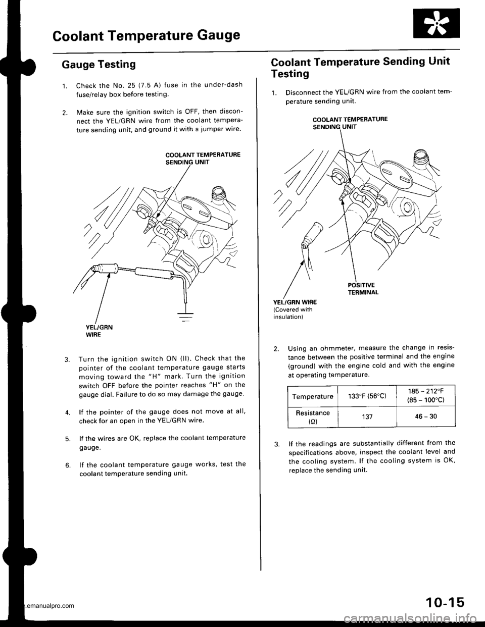
2. Make sure the ignition switch is OFF, then discon-
nect the YEL/GRN wire from the coolant tempera-
ture sending unit. and ground it with a jumper wire.
YEL/GRNWIRE
Turn the ignition switch ON {ll). Check that the
pointer of the coolant temperature gauge starts
moving toward the "H" mark. Turn the ignition
switch OFF before the pointer reaches "H" on the
gauge dial. Failure to do so may damage the gauge.
lf the pointer of the gauge does not move at all,
check for an open in the YEL/GRN wire.
lf the wires are OK, replace the coolant temperature
gauge.
lf the coolant temperature gauge works, test the
coolant temperature sending unit.
5.
COOLANT TEMPERATURE
Coolant Temperature Sending Unit
Testing
1. Disconnect the YEUGRN wire from the coolant tem
perature sending unit.
COOLANT TEMPERATURE
POSITIVETERMINAL
YEL/GRN WIRE(Covered withinsulation)
2. Using an ohmmeter, measure the change in resis-
tance between the positive terminal and the engine
(ground) with the engine cold and with the engine
at operating temPerature.
Temperature133.F (56'C)1A5 - 212F
(8s - 100'c)
Resistance(0)13746-30
3. lf the readings are substantially different from the
specitications above, inspect the coolant level and
the cooling system. lf the cooling system is OK,
replace the sending unit.
10-15
www.emanualpro.com
Page 204 of 1395
Fuel and Emissions
Special Tools ...................... 11-2
Component Locations
lndex ...................... ....,.... 11-3
Svstem Description
Vacuum Connections ...........,....,.,................. 1 1-9
Electrical Connections ................................... 1 1-15
System Connectors .,.,,.,............................,.,. 1 1-36
Troubleshooting
Troubleshooting Procedures,.,..................... 11-60
Engine Control Module/Powertrain ConttolModule Terminal Arrangement .............., 11-67
Diagnostic Trouble Code Chart .................... 1 t-75
How to Read Flowcharts .......,.....,.,............... I 1-79
PGM-Fl System
System Description .................,.,.,,,............... 1 1-80
Troubleshooting Flowcharts
Engine Control Module/PowertrainControl Module ........11-52
Manifold Absolute Pressure Sensor ............. 11-90
Intake Air Temperature Sensor .................... 1 1-95
Engine Coolant Temperature Sensor .,..,.,.... 1 1-99
Throttle Position Sensor ...........,.....,.,.,..,...... I 1'103
Primary Heated Orygen Sensor (Sensor 1) ... 11-110
Secondary Heated Oxygen Sensor{Sensor 2l .................. 1 1-117
Heated Oxygen Sensor Heater ..................... 11-121
Fuef Supply System ......11-124
Random Misfire ,....,.,..... 11-126
Mistire Detected in One Cylinder .....-........... 11-128
Knock Sensor ................ 11-130
CKP/TDC/CYP Sensor .................................... 1 1-131
Vehicle Speed Sensor ...............................,.... 1 1-135
Barometric Pressure Sensor .....,...,...,.,,........ 1 1-137
Electrical Load Detector ...,.,.......................... 1 1-138
CKF Sensor ................,.,, '11-112
ECM/PCM lnternaf Circuit ............................. 11'117
HO2S Replacement .,.,.,. 11-148
ldle Control System
System Description ............ 11-149
Troubleshooting Flowcharts
ldle Control System ...... 11-150
fdle Air Control Valve ......................,............. 11-152
Air Conditioning Signal ................................. I 1-155
Alternator FR Signal ...................................... 1 1-159
Starter Switch Si9na1 .................................... t l-161
Power Steering Pressure Switch Signal ...... 11-162
Brake Switch Si9na1 ...................................... 11-166
Fast ldle Thermo Valve .,.,.............................,.,.,. 11-168
ldle speed setting .............. 11-169
Fuel Supply System
Fuel Lines ............................ 11-171
Fuef Tube/Ouick-Conneci Fittings ..................... 11 -175
System Description ............ 11-178
Fuel Pressurg ...................... 11-178
Fuel Iniectors ................,..... 11-179
Fuel Pressure Re9u1ator .............................,.,...., f 1-181
Fuef Fifter ....,.,.,.,,,,.,............11-142
Fuel Pump ........................... 11-183
Fuel Gauge .......................... 11-184
Fuel Gauge Sending Unit ................................... I 1-185
Low Fuel Indicator System ...........,.,..,............... 1 1-185
PGM-FI Main Relay ............. 11-187
Fue|Tank................ ............. 11-191
Intake Air System
System Description ............ 11-193
Air Cleanel ,.,.,..................... 11-194
Throttle Cable ..................... 11-194
Throttle Body........ .............. 11-196
Emission Control System
System D$cription ...,....,.,. 11-199
Tailpipe Emission ............... 11-199
Three Way Catalytic Converter ..................,.,...,, 11-199
Positive Crankcase Ventilation System .,.,,,,.,.., 11-2O1
Evaporative Emission Controls .........,.,.,............ 11-203
www.emanualpro.com
Page 210 of 1395
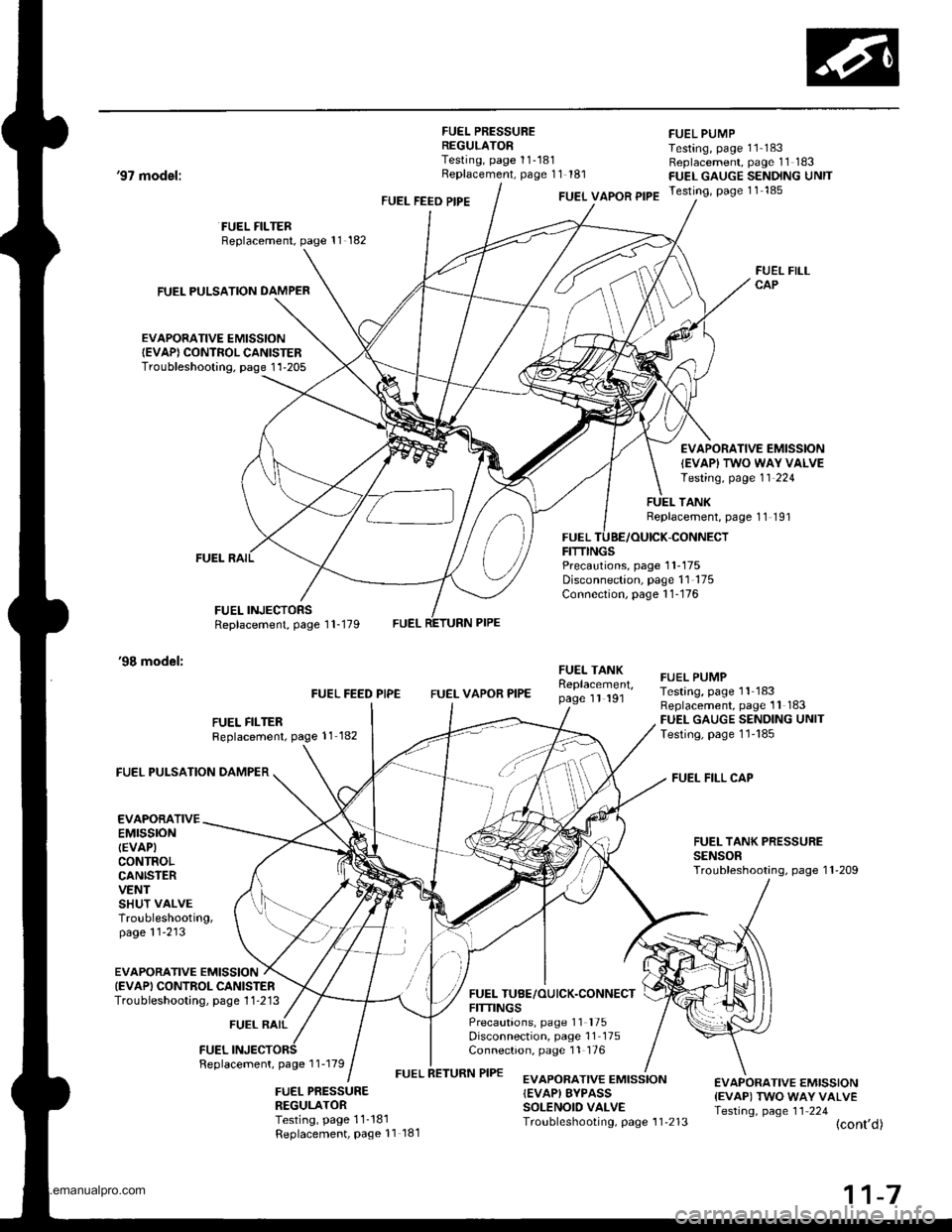
FUEL PRESSUREREGULATORTesting, page 11-181Replacement, page 11 181
FUEL PUMPTesting, page 11 183Replacement, page 11 183FUEL GAUGE SENDING UNITTesting, page 11 185
'97 model:
'98 model:
FUEL PULSATION DAMPER
EVAPORATIVE EMISSIONIEVAP) CONTROL CANISTERTroubleshooting. page 1'l-205
FUEL FILTERReplacement, page 11 182
FUEL INJECTORSReplacement, page 1 1-179
FUEL FEED PIPEFUEL VAPOR PIPE
FUELFITTINGS
FUEL FILLCAP
EVAPORATIVE EMISSION
IEVAPI TWO WAY VALVETesting, page 11 224
TANKReplacement, page 11 191
-CONNECT
Precautions, page 1 1-175Disconnection, page 11 175Connection, page 1 1-176
FUEL FILTERReplacement, page 11 182
FUEL FEED PIPEFUEL VAPOR PIPE
FUEI- TANKReplacement,page 1l 191
FUEL TUBE/OUICK.CONNECTFITTINGSPrecautions, page 11 '175
Disconnection, page 11 175Connection, page 11 176
FUEL PUMPTesting, page 11 183Replacement, page 11 183FUEL GAUGE SENDING UNITTesting, page 1l'185
FUEL FILL CAP
FUEL TANK PRESSURESENSORTroubleshooting, page 1 l-209
FUEL PULSATION DAMPER
EVAPORATIVEEMTSSTONIEVAPICONTROLCANISTERVENTSHUT VALVETroubleshooting,page 11'213
EVAPORATIVE EMISSIONIEVAPI CONTROL CANISTERTroubieshooting, page 1 1 -213
FUEL RAIL
FUELFeplacement, page 1 1-179
FUEL PRESSURENEGULATORTesting, page 11-181Replacement, Page 11 181
EVAPORATIVE EMISSION{EVAP) EYPASSSOLENOID VALVETroubleshooting, page 1 1'213
€VAPORATIVE EMISSION{EVAP) TWO WAY VALVETesting, page 11 224(cont'd)
www.emanualpro.com
Page 211 of 1395
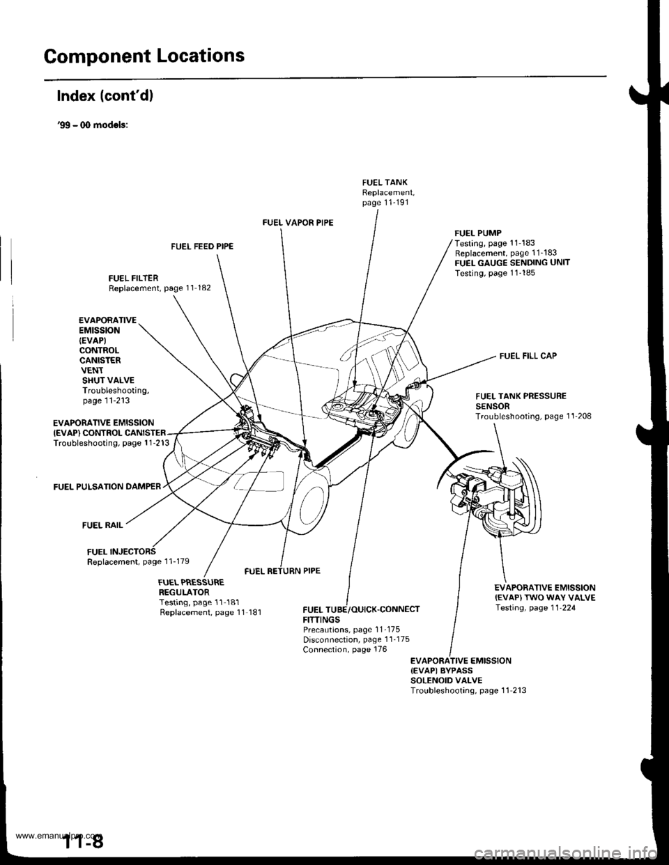
Gomponent Locations
Index lcont'd)
'99 - (X) modols:
FUEL TANKReplacement,page 11-191
FUEL FEED PIPE
FUEL FILTERReplacement, page 11 182
FUEL VAPOR PIPE
FUELFITTINGS
FUEL PUMPTesting, page '11 183Replacement, page 1 1_183FUEL GAUGE SENDING UNITTesting, page 11-185
FUEL FILL CAP
EVAPORATIVE EMISSIONIEVAP) CONTROLTroubleshooting, page 1 1-213
FUEL PULSATION DAMPER
FUEL RAIL
FUELReplacement, page 1 1-179
EVAPORATIVEEMtSStON
IEVAP)CONTROLCANISTERVENTSHUT VALVETroubleshooting,page 11-213FUEL TANK PRESSURESENSORTroubleshooting, page 1'l'208
EVAPORATIVE EMISSION{EVAP) TWO WAY VALVETesting, page 11-224
FUEL PRESSUREREGULATORTesting, page 11-181Replacement, page 11 181,CONNECT
PrecaLrtions, page 1 1-175Disconnection, page 1 1-175Connection, page 176
EVAPORATIVE EMISSION{EVAPI BYPASSSOLENOID VALVETroubleshooting, page 11 213
www.emanualpro.com
Page 264 of 1395
Troubleshooting
Troubleshooting Procedures (cont'd)
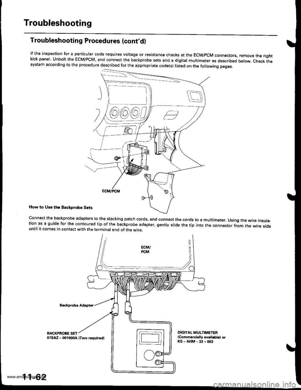
lf the inspection for a particular code requires voltage or resistance checks at the EcM/pcM connectors, remove the rightkick panel. Unbolt the EcM/PcM. and connect the backprobe sets and a digital multimeter as described below, check thesystem according to the procedure described for the appropriate code(s) listed on the following pages.
How to Us6 tho Backprobe S6ts
Backp.obo Adapto.
BACKPROBE SET
connect the backprobe adapters to the stacking patch cords. and connect the cords to a multimeter. Using the wire insula-tion as a guide for the contoured tip of the backprobe adapter, gently slide the tip into the connector from the wire sideuntil it comes in contact with the terminal end of the wire.
DIGITAI. MULTIMETER(Commarci.lly rvrilabl.l orKS-AHM-32-@3
@@)@)c,
11-62
o'SAZ - (xtlqDA lTwo requir.dl
www.emanualpro.com
Page 267 of 1395
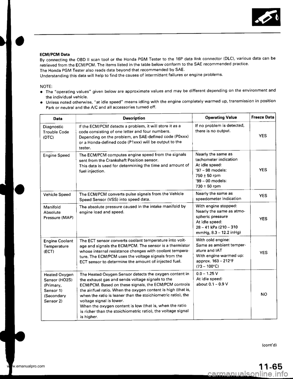
ECM/PCM Data
By connecting the OBD ll scan tool or the Honda PGM Tester to the 16P data link connector (OLC), various data can be
retrieved from the ECM/PCM. The items listed in the table below conform to the SAE recommended practice
The Honda PGM Tester also reads data beyond that recommended by SAE.
understanding this data will help to find the causes of intermittent failures or engine problems.
NOTE:
The ',operating values" given below are approximate values and may be different depending on the environment and
the individual vehicle.
Unless noted otherwise. "at idle speed" means idling with the engine completely warmed up, transmission in position
Park or neutral and the A,./C and all accessories turned otf.
DataDesc.iptionOp€rating ValuoFreeze Data
Diagnostic
Trouble Code
(DTC)
lf the ECM/PCM detects a problem, it will store it as a
code consisting of one letter and tour numbers
Depending on the problem, an SAE-defined code (Poxxx)
or a Honda-defined code (P'lxxx) will be output to the
tester.
lf no problem is detected,
there is no output.
YES
Engine SpeedThe ECN4/PCN4 computes engine speed from the signals
sent from the Crankshaft Position sensor.
This data is used for determining the time and amount of
fuel iniection.
Nearly the same as
tachometer indication
At idle speed:'97 - 98 models:
750 t 50 rpm'99 - 00 models:
730 f 50 rpm
YES
Vehicle SpeedThe ECM/PCM converts pulse signals from the Vehicle
Speed Sensor (VSSI into speed data.
Nearly the same as
speedometer indicationYES
Manifold
Absolute
Pressure (MAP)
The absolute pressure caused in the intake manifold by
engine load and speed.
With engin6 stopped:
Nearly the same as atmo-
spheric pressure
At idle speed:
2a - 41 kPa {210 - 310
mmHg, 8.3 - 12.2 inHg)
YES
Engine Coolant
Temperature
{ECT)
The ECT sensor converts coolant temperature into volt-
age and signals the ECM/PCM. The sensor is a thermistor
whose internal resistance changes with coolant tempera-
ture. The ECM/PCM uses the voltage signals from the
ECT sensor to determine the amount of injected fuel
With cold engine:
Same as ambient temPer-
ature and IAT
With engine warmed uP:
approx. 163 - 2'12'F
(73 - 100"c)
YES
Heated Oxygen
Sensor (HO25)
(Primary,
Sensor 1)
(Secondary
Sensor 2)
The Heated Oxygen Sensor detects the oxygen content in
the exhaust gas and sends voltage signals to the
ECMiPCM. Based on these signals, the ECM/PCM controls
the airlfuel ratio. When the oxygen content is high (that is.
when the ratio is leaner than the stoichiometric ratio), the
voltage signal is lower.
When the orygen content is low (that is, when the ratio
is richer than the stoichiometric ratio), the voltage signal
is higher.
0.0 - 1.25 V
At idle speed:
about 0.1 - 0.9
NO
(cont'd)
1 1-65
www.emanualpro.com
Page 269 of 1395
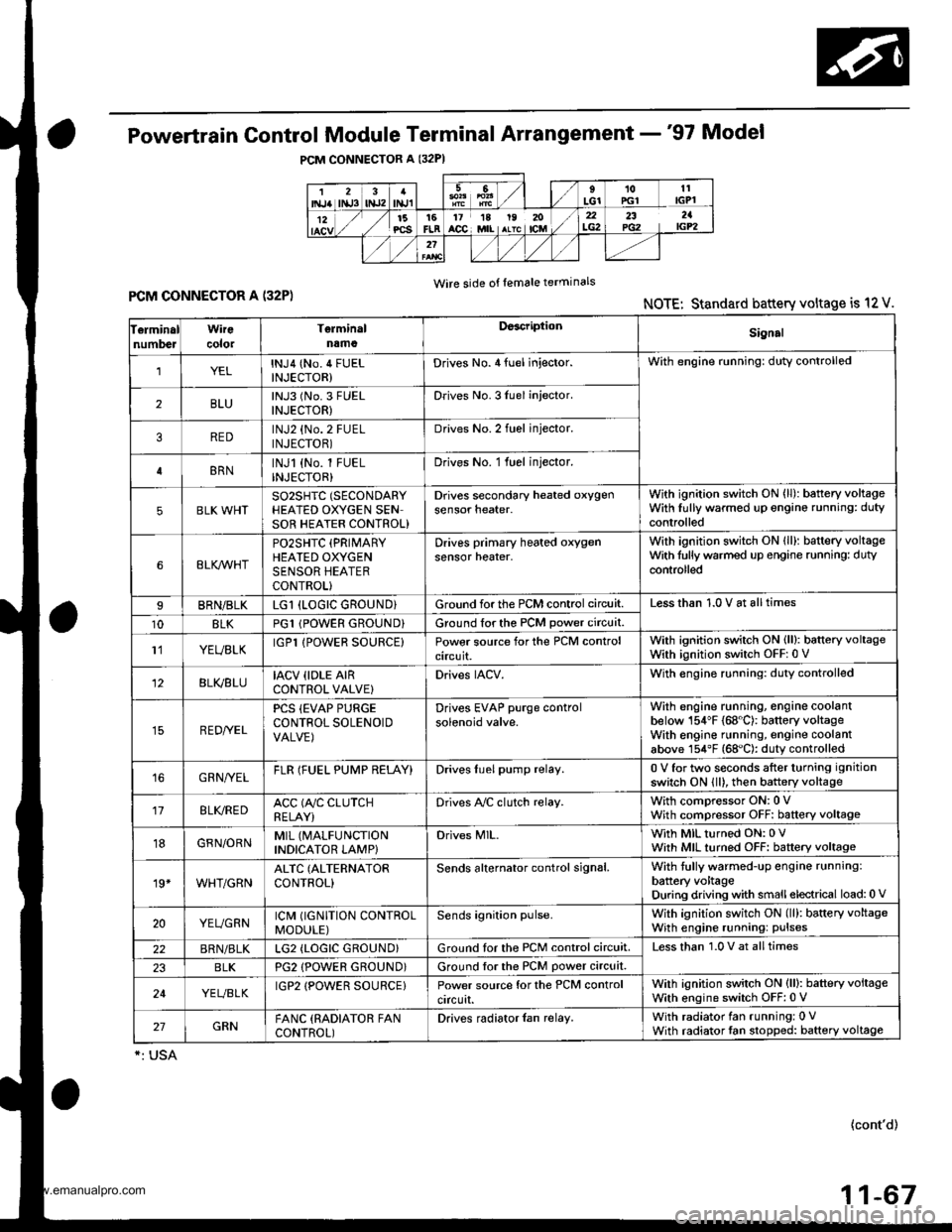
Powertrain Control Module Terminal Arrangement -'97 Model
FCM CONNECTOR A (32P)NOTE: Standard battery voltage is 12 V.
Wire side of lemale terminals
f€rminalnumlreJWirecolor
Telminalnama
DescriptionSignal
YELlNJ4 (No.4 FUELINJECTOR)Drives No. 4 {uel injector.With engine running: duty controlled
2BLUlNJ3 (No.3 FUELINJECTOR)Drives No. 3luel injector.
REDlNJ2 {No.2 FUELINJECTOR)Drives No.2 tuel injector.
BRNlNJl (No. l FUELINJECTOR)Drives No. 1 fuel injector.
5BLK WHTSO2SHIC (SECONDARY
HEATED OXYGEN SENSOR HEATER CONTROL)
D ves secondary heated oxygensensor heater.With ignition switch ON {ll): battery voltageWith fully warmed up engino running: dutycontrolled
6BLKAr'YHT
PO2SHTC (PRIMARY
HEATED OXYGENSENSOR HEATERCONTROL}
Drives primary heated oxygensensor heater,With ignition switch ON lll): battery voltagewith fully warmed up engine running: dutycontroll6d
I8RN/BLKLGl (LOGIC GROUND}Ground forthe PCM control circuit.Less than 1.0 V at all times
10BLKPG1 lPOWER GROUND}Ground for the PCM power circuit.
l1YEUELKIGPl lPOWER SOURCE}Power source for the PCM controlcircuit.
With ignition switch ON (ll): battery voltageWith ignition switch OFF: 0 V
12BLI(BLUIACV {IDLE AIRCONTROL VALVE}Drives IACV.With €ngine running: duty controlled
REDryEL
PCS (EVAP PURGECONTFOL SOLENOIDVALVE)
Drives EVAP purge controlsolenoid valve.
With engine running, engine coolantbelow 154'F (68"C): battery voltageWith engine running, engine coolantabove 154"F (68"C): duty controlled
16GRN/VELFLR (FUEL PUMP RELAY)Drives Iuel pump relay.0 V for two seconds after turning ignition
switch ON lll), then battery voltage
118LI(REDACC (A,/C CLUTCHRELAY}Drives Ay'C clutch relay.With comoressor ON: 0 VWith compressor OFF: baftery voltage
18GRN/ORNMIL (MALFUNCTION
INDICATOR LAMP}Drives MlL.With MIL turned ON: 0 VWith MIL turned OFF: baftery voltage
19*WHT/GRNALTC (ALTERNATOR
CONTROL}Sends alternator control signal.With tully warmed-up engine running:
battery voltageDuring driving with smallelectrical load:0 '
20YEUGRNICM (IGNITION CONTROLMODULE)Sends ignition pulse.With ignition switch ON (ll): baftery voltageWith engine running: pulses
22BRN/BLKLG2 (LOGIC GROUND}Ground tor the PCM control circuit.Less than 1.0 V at alltimes
23BLKPG2 {POWER GROUND}Ground lor the PCM power circuit.
24YEUBLKIGP2 {POWER SOURCE}Power source for the PCM controlcircuit.
With ignition switch ON (ll): battery voltage
With engine switch OFF: 0 V
27GRNFANC (RADIATOR FANCONTROL)Drives radiator {an relay.With radiator fan running: 0 VWith radiator fan stopped: baftery voltage
*: USA
{cont'd)
11-67
www.emanualpro.com