HONDA CR-V 1998 RD1-RD3 / 1.G Workshop Manual
Manufacturer: HONDA, Model Year: 1998, Model line: CR-V, Model: HONDA CR-V 1998 RD1-RD3 / 1.GPages: 1395, PDF Size: 35.62 MB
Page 731 of 1395
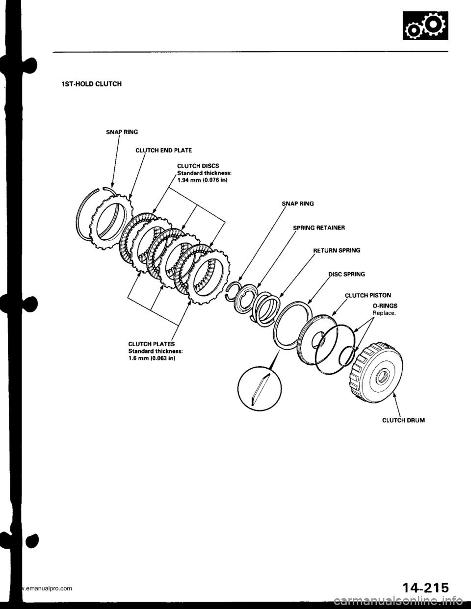
lST-HOLD CLUTCH
thickness:
RETURN SPRING
c
/
LUTCH PISTON
O.RINGS
14-215
www.emanualpro.com
Page 732 of 1395
Clutch
Disassembly
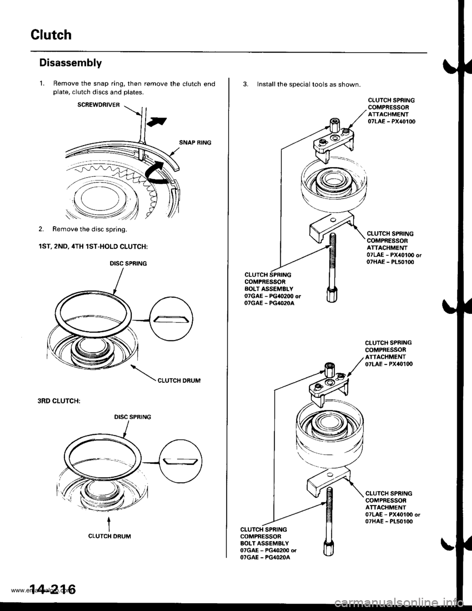
l. Remove the snap ring, then remove the clutch endplate, clutch discs and plates.
SCREWORIVER
SNAP RING
2. Remove the disc spring.
1ST, 2ND, 4TH lST-HOLD CLUTCH:
CLUTCH DBUM
3RD CLUTCH:
-'=*.=:--
'..p
Remove the disc spring.
DISC SPRING
DISC SPRING
14-216
3. Install the special tools as shown.
CLUTCHCOMPRESSORAOLT ASSEMBLY07GAE - FGao2OO orOTGAE . PG4O2OA
CLUTCH SPNINGCOMPRESSORATTACHMENT07LAE - PX40100
CLUTCH SPRINGCOMPRESSORATTACHMENT07LAE - PX4010O or07HAE - PL50100
CLUTCH SPRINGCOMPRESSORATTACHMENT07LAE - PX40t00
CLUTCH SPRINGCOMPRESSORATTACHMENT07LAE - PX4010O or07HAE - PL50100
CLUTCH SPRINGCOMPRESSORBOLT ASSEMBLY07GAE - PG0200 orOTGAE - PG4O2OA
www.emanualpro.com
Page 733 of 1395
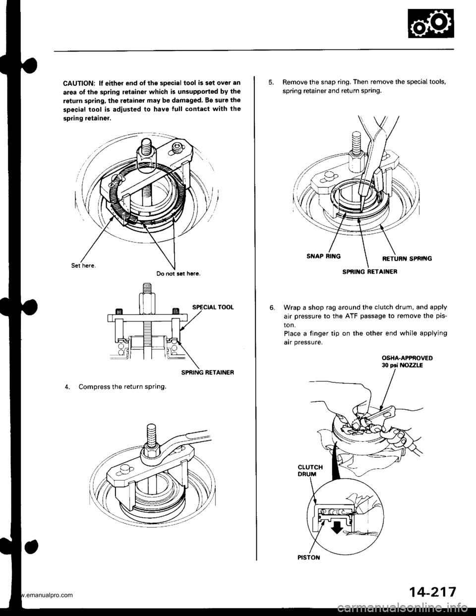
CAUTION: lf either end ot the special tool issetover an
area of the spring retainer which is unsupported by the
return spring, the retainer may be damaged. B€ sure the
special tool is adiusted to have lull contact with the
spring retainer.
SPRING RETAINER
4. Compress the return spring.
Do not s6t h6re.
5. Remove the snap ring, Then remove the special tools,
spring retainer and return spring.
Wrap a shop rag around the clutch drum, and apply
air pressure to the ATF passage to remove the pis-
ton.
Place a finger tip on the other end while applying
arr pressure.
OSHA.APPROVED
SPRIlIG RETAINER
14-217
www.emanualpro.com
Page 734 of 1395
Glutch
Reassembly
NOTE:
. Clean all parts thoroughly in solvent or carburetorcleaner, and dry them with compressed air.. Blow out all passages.
o Lubricate all parts with ATF before reassembly.
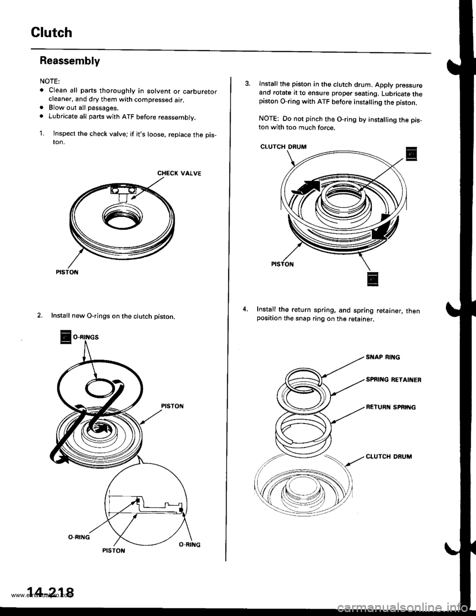
1. Inspect the check valve; if it's loose, replace the pis_ton.
CHECK VALVE
2. Install new O-rings on the clutch piston.
PtsTot{
14-218
3. Install th€ piston in the clutch drum. Apply pressure
and rotate it to ensure proper seating, Lubricate thepiston O-ring with ATF betore insta ing the piston.
NOTE: Oo not pinch the O-ring by installing the pis_ton with too much force.
CLUTCH DRUM
Install the return spring, and spring retainer, thenposition the snap ring on the retainer.
4.
SI{AP RING
SPAI'{G RETAIIIER
REIURN SPRING
CLUTCH DRUM
www.emanualpro.com
Page 735 of 1395
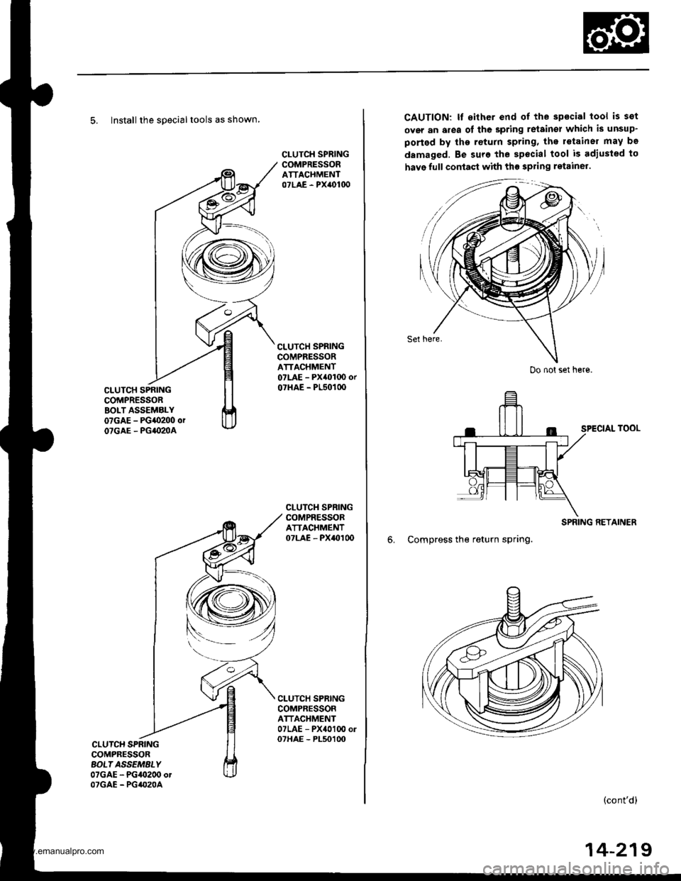
5. Install the specialtools as shown
CLUTCH SPRINGCOMPRESSORBOLT ASSEMALY07GAE - PG{0200 orOTGAE - PG|(IMA
CLUTCH SPRINGCOMPRESSORATTACHMENT07LAE - PX40100
CLUTCH SPRINGCOMPRESSORATTACHMENT07LAE - PX40100 orO?HAE - PL5O1OO
CLUTCH SPRINGCOMPRESSORATTACHMENT07LAE - PXaOI 0o
CLUTCH SPRINGCOMPRESSORATTACHMENT07LAE - PX4010O ol07HAE - PL50100CLUTCH SPRINGCOMPBESSORAOL| ASSEMALY07GAE - PG/9t200 otOTGAE - PG/(,20A
CAUTION: It sither end of the spscial tool is sot
over an area of the spring retain€l which is unsup'
ported by the return spring, the retainer may be
damaged. Be sure the special tool is adiusted to
have full contaqt with th€ spring ratainel.
Set here.
SPECIAL TOOL
SPRING RETAINER
6. Compress the return spring.
(cont'd)
Do not set here.
14-219
www.emanualpro.com
Page 736 of 1395
Clutch
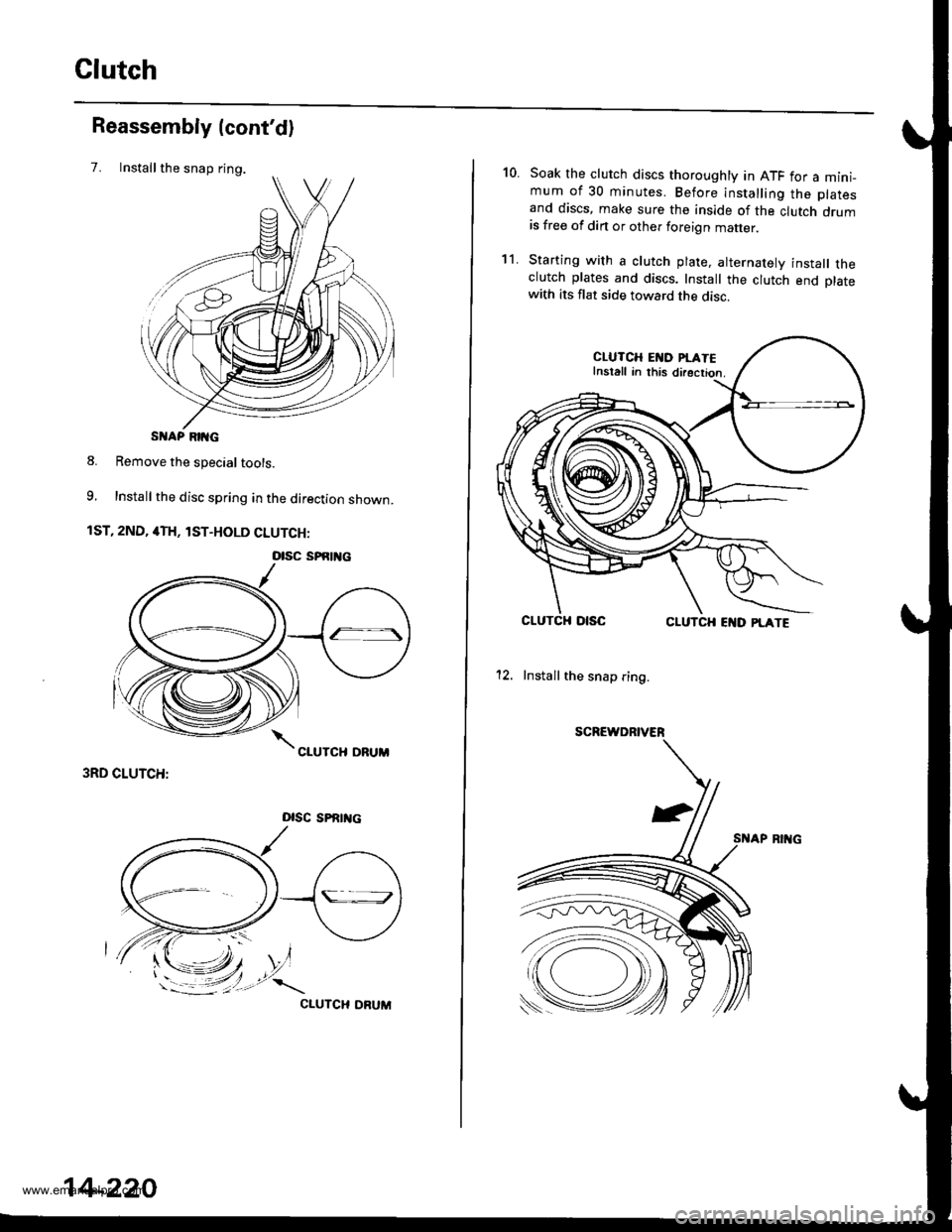
Installthe snap ring.
Reassembly (cont'd)
7.
S AP RIIG
8. Remove the special tools.
9, Install the disc spring in the direction shown.
1ST, 2ND, 4TH, lST-HOLD CLUTCH:
3RD CLUTCH:
Dlsc sPRrrtc
CIUTCH ORUM
otsc sPfitl{c
14-220
10.Soak the clutch discs thoroughly in ATF for a mini_mum of 30 minutes. Before installing the platesand discs, make sure the inside of the clutch drumis free of din or other foreign matter
Starting with a clutch plate, alternatelv install theclutch plates and discs. Install the clutch end platewith its flat side toward the disc.
CLUTCH EI{D PI.ATEInstall in this directior.
CLUTCHCLUTCH EI{D PLATE
12. Install the snap ring.
SCREWDRIVER
't1.
www.emanualpro.com
Page 737 of 1395
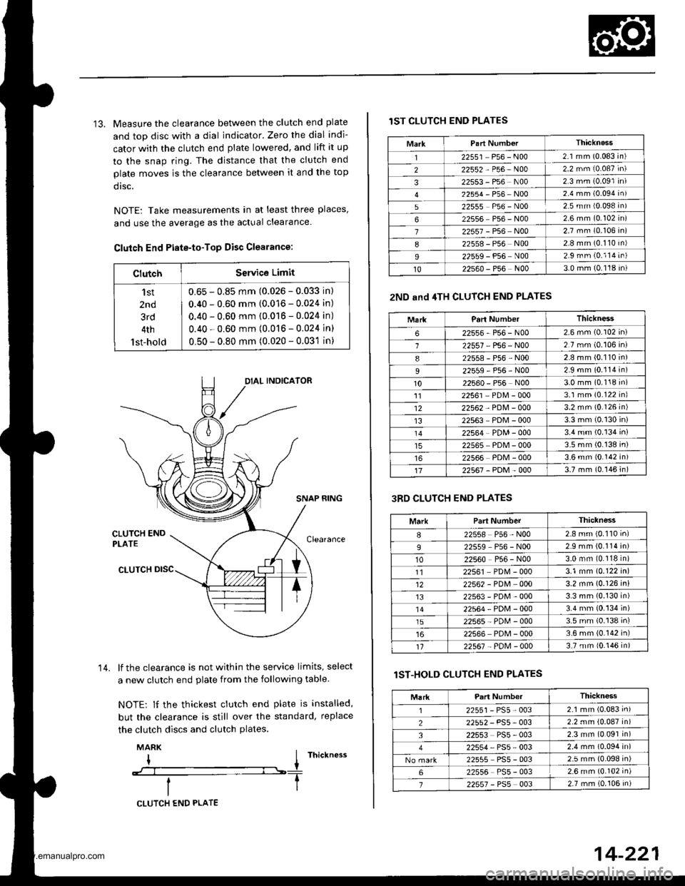
13. Measure the clearance between the clutch end plate
and top disc with a dial indicator. Zero the dial indi-
cator with the clutch end plate lowered, and lift it up
to the snap ring. The distance that the clutch end
plate moves is the clearance between it and the top
dtsc.
NOTE: Take measurements in at least three places'
and use the average as the actual clearance.
Clutch End Ptate-to-Top Disc Clearance:
ClutchService Limit
'l st
2nd
3rd
4th
lst-hold
0.65 - 0.85 mm (0.026 - 0.033 in)
0.40 - 0.60 mm (0.016 - 0.024 in)
0.40 - 0.60 mm (0.016 - 0.024 in)
0.40 - 0.60 mm (0.016 - 0.024 in)
0.50 - 0.80 mm (0.020 - 0.031 in)
SNAP RING
lf the clearance is not within the service limits, select
a new clutch end plate from the following table
NOTE: lf the thickest clutch end plate is installed,
but the clearance is still over the standard, replace
the clutch discs and clutch plates.
MARK
I I rnictness
--:--l----T
14.
CLUTCH END PLATE
14-221
lST CLUTCH END PLATES
2ND and 4TH CLUTCH END PLATES
3RD CLUTCH END PLATES
lST-HOLD CLUTCH END PLATES
MarkThicknass'I22551 P56 - N002.1 mm (0.083 in)
222552-P56-N002.2 mm (0.087 in)
322553 - P56 N002 3 mm (0.091 in)
22554-P56-NOo2.4 mm (0.094 in)
522555 P56 - N002.5 mm {0.098 in)
622556 P56 - N002 6 mm (0.102 in)
722557 - P56 N002.7 mm (0.106 in)
822558 - P56 N002.8 mm (0.110 in)
I22559 - P56 N002.9 rnm (0.114 in)
1022s60 - P56 N003.0 mm (0.118 in)
MarkParl NumberThickness
622556-P56-N002.6 mm (0.102 in)
122557 P56 - N002.7 mm (0.106 in)
822558-P56-N002.8 mm (0.110 in)
22559-P56-N002.9 mm (0.114 in)
1022560 - P56 N003.0 mm (0.118 in)'1122561 PDM - 0003.1 mm (0.122 inl
1222562 - PDM - 0003.2 mm {0.126 in)
1322563 PDM - 0003.3 mm (0.130 in)
22564 PDM - 0003.4 mm (0.134 in)
22565 PDM - 0003.5 mm (0.138 in)
22566 PDM - 0003.6 mm 10.142 in)
1722567-PDM-0003.7 mm (0.146 in)
MarkPart NumberThiclness
I22558 P56 - N002.8 mm (0.110 inl
922559 P56 - N002.9 mm (0.114 in)
1022560 P56 - N003.0 mm (0.118 in)
1122561 PD[4 - 0003.1 mm (0.122 in)
1222562 - PDM 0003.2 mm (0.126 in)
t322563-PDM-0003.3 mm (0.130 in)'1422564-PDN4-0003.4 mm (0.134 in)
1522565-PD[,l-0003.5 mm (0.138 in)
22566 PDM - 0003.6 mm (0.142 in)'t122567 - PoM - 0003.7 mm {0.146 in)
Thickness
2255r-PS5-0032.1 mm (0.083 in)
22552 - PS5- 0032.2 mm {0.087 in)
322553 PS5 - 0032.3 mm (0.091 in)
22554, PS5 - 0032.4 mm (0.094 in)
22555 PS5 - 0032.5 mm (0.098 in)
622556 PS5 - 0032.6 mm {0.102 in)
722557 - PSs 0032.7 mm (0.106 in)
www.emanualpro.com
Page 738 of 1395
Differential
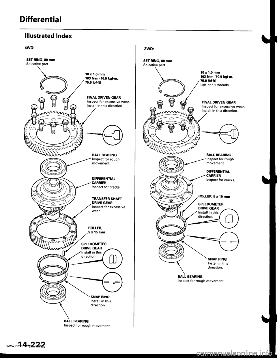
lllustrated Index
'lWD:
SET RING, 80 mmSelective part
10 x 1.0 mm103 N.m (10.5 kgt.m,?5.9 tbtftl
FINAL ORIVEN GEARlnspect for excessive wear,Install in this direction.
BALL BEARINGInspect for rough
DIFFERENTIAI.CARRIERlnspect for cracks.
TRANSFER SHAETDNlvE GEARInspect for excessive
SPEEDOMETERDRIVE GEARInstall in thisdirection.
SNAP RINGInstall in thisdirection.
BALL BEARINGInspect for rough movement,
14-222
2WDl
SET nlNG, 80 mmSel6ctive part
A,U
,gBc
10 x 1.0 mm103 N.m {10.5 kg[.m,75.9 tbt.ftlLeft-hand threads
FINAL ORIVEN GEARInspect for excessive wear,Install in thls direction.
BALL BEABINGInspect for rough
DIFFERENTIAI.CARRIERInspect for cracks.
ROLLER,5 x 10 mm
SPEEDOMETERDRIVE GEARInstall in thisdirection.
SNAP RINGInstall in thisdirection.
BALL BEARING
www.emanualpro.com
Page 739 of 1395
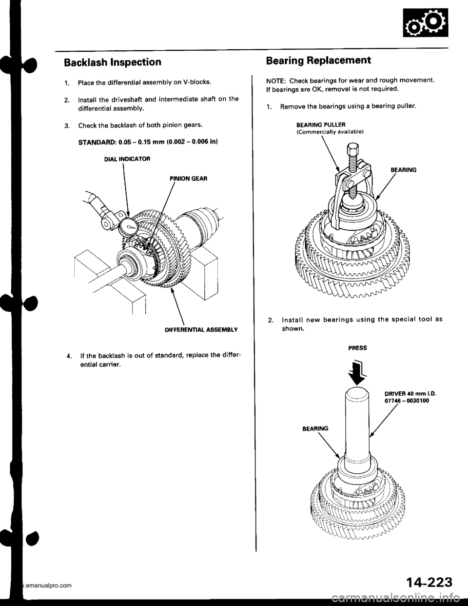
Backlash Inspection
Place the differential assembly on V-blocks.
lnstall the driveshaft and intermediate shaft on the
differential assemblY.
Check the backlash of both pinion gears.
STANDARD: 0.05 - 0.15 mm (0.002 - 0.006 in)
OIFFEBENNAL ASSEMBLY
It the backlash is out of standard, replace the difter-
ential carrier.
1.
DIAL INDICATOR
Bearing Replacement
NOTE: Check bearings for wear and rough movement.
lf bearings are OK, removal is not required.
1. Remove the bearings using a bearing puller.
BEARING PULLER(Commercially available)
lnstall new
snown.
bearings using the sPecial tool
PRESS
14-223
www.emanualpro.com
Page 740 of 1395
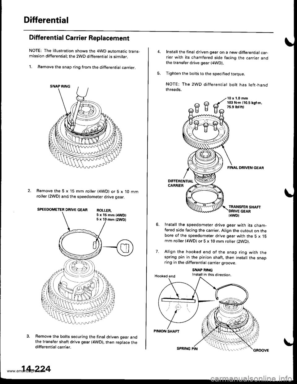
Differential
Differential Carrier Replacement
NOTE: The illustration shows the 4WD automatic trans-mission differential; the 2WD differential is similar.
1. Remove the snap ring from the differential carrier.
Remove the 5 x 15 mm roller (4WD) or 5 x 10 mmroller (2WDl and the speedometer drive gear.
SPEEDOMETER DRIVE GEAR RoI I FP
Remove the bolts securing the final driven gear andthe transfer shaft drive gear (4WD), then replace thedifferential carrier.
5 x 15 mm (/tWD)5 x 10 mm {2WDl
14-224
SPRING PINGROOVE
Install the final driven gear on a new differential car-rier with its chamfered side facing the carrier andthe transfer drive gear (4WD),
Tighten the bolts to the specified torque.
NOTE: The 2WD differentiat bolt has left-handthreads,
10 x 1.0 mm103 N.m 110.5 kd.m,7s.9 rbr.ft)
7.
FINAL DRIVEN GEAR
TRANSFER SHAFT
Install the speedometer drive gear with its cham-fered side facing the carrier. Align the cutout on thebore of the speedometer drive gear with the 5 x 15mm roller (4WD) or 5 x 10 mm roller (2WD).
Align the hooked end of the snap ring with thespring pin in the pinion shaft. then install the snaoring in the differential carrier groove
SNAP RINGInstall in this direction.Hooked end
PINION SHAFT
{4WDl
www.emanualpro.com