Arm HONDA CR-V 1998 RD1-RD3 / 1.G Workshop Manual
[x] Cancel search | Manufacturer: HONDA, Model Year: 1998, Model line: CR-V, Model: HONDA CR-V 1998 RD1-RD3 / 1.GPages: 1395, PDF Size: 35.62 MB
Page 13 of 1395
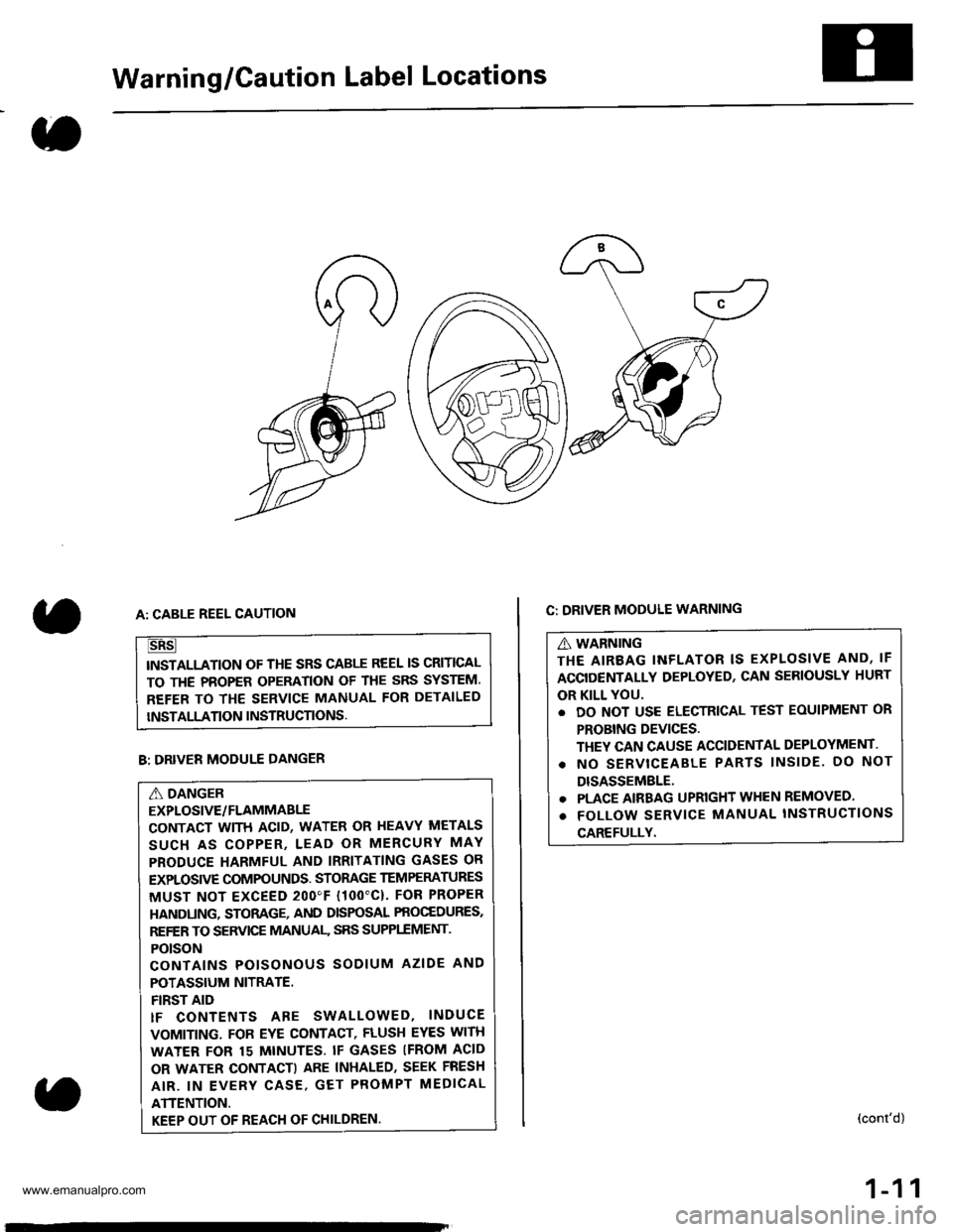
Warning/Caution Label Locations
C: DRIVER MODULE WARNING
A WARNING
THE AIREAG INFLATOR IS EXPLOSIVE AND, IF
ACCIDENTALLY DEPLOYED, CAN SERIOUSLY HURT
OR KILL YOU.
. DO NOT USE ELECTRICAL TEST EOUIPMENT OR
PROBING DEVICES.
THEY CAN CAUSE ACCIDENTAL DEPLOYMENT.
. NO SERVTCEABLE PARTS lNSlDE. DO NOT
DISASSEMBLE.
. PLACE AIRBAG UPRIGHT WHEN REMOVED
. FOLLOW SERVICE MANUAL INSTRUCTIONS
CAREFULLY.
A: CABLE REEL CAUTION
TNSTALLATION OF THE SRS CABLE REEL IS CRITICAL
TO THE PBOPER OPERATION OF THE SRS SYSTEM.
REFER TO THE SERVICE MANUAL FOR DETAILED
INSTALLATION INSTRUCTIONS.
(cont'd)
1-11
B: DRIVER MODULE DANGER
A DANGER
EXPLOSIVE/FLAMMABLE
CONTACT WITH ACID, WATER OR HEAVY METALS
SUCH AS COPPER, LEAD OR MERCURY MAY
PRODUCE HARMFUL AND IRRITATING GASES OR
EXPLOSIVE COMPOUNDS. STOMGE TEM PERATURES
MUST NOT EXCEED 2OO"F {1OO'C}. FOR PROPER
HANDUNG, STORAGE, AND DISPOSAL PROCEDURES.
REFER TO SERVICE MANUAI- SRS SUPPI.EMENT,
POTSON
CONTAINS POISONOUS SODIUM AZIDE AND
POTASSIUM NITRATE.
FIRST AID
tF CONTENTS ARE SWALLOWED, INDUCE
VOMITING. FOR EYE CONTACT, FLUSH EYES WITH
WATER FOR 15 MINUTES. IF GASES IFROM ACID
OR WATER CONTACTI ARE INHALED, SEEK FRESH
AIR. IN EVERY CASE, GET PROMPT MEDICAL
ATTENTION.
KEEP OUT OF REACH OF CHILDREN
www.emanualpro.com
Page 15 of 1395
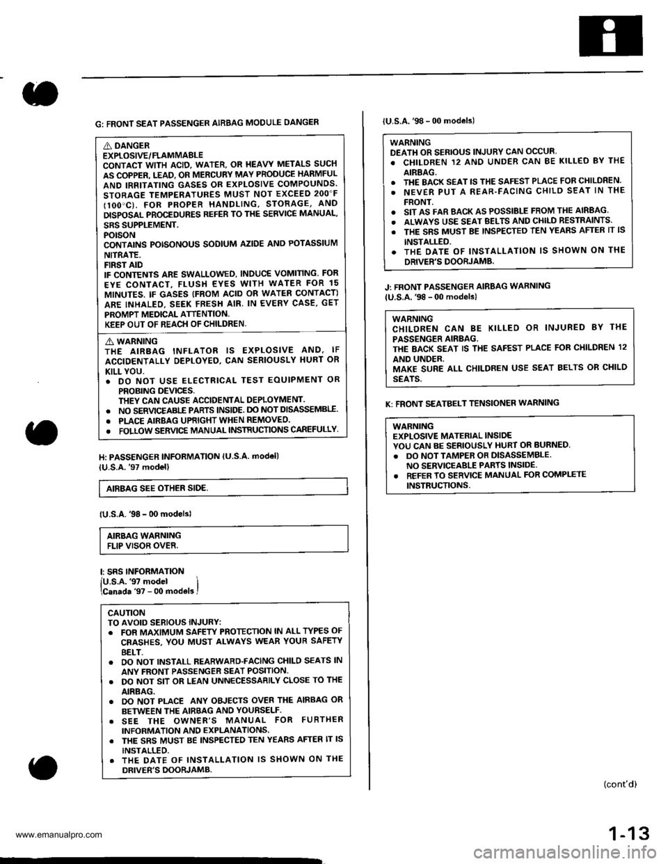
G: FRONT SEAT PASSENGER AIRBAG MODULE DANGEN
A DANGEREXPLOSIVE/FLAMMABLECONTACT WITH ACID, WATER. OR I{EAVY METALS SUCH
AS COPPER. T.EAD. OR MERCURY MAY PRODUCE HARMFUL
AND IRRITATING GASES OR EXPLOSIVE COMPOUNDS.
STORAGE TEMPERATURES MUST NOT EXCEED 2OO"F
IlOO'C). FOR PROPER HANDLING, STORAGE, AND
DISPOSAL PROCEDURES REFER TO THE SERVICE MANUAL,
SRS SUPPLEMENT.POTSONCONTAINS POTSONOUS SODIUM AZIDE ANO POTASSIUM
NITRATE.FIRST AIDIF CONTENTS ARE SWALLOWED, INDUCE VOMITING. FOR
EYE CONTACT, FLUSH EYES WITH WATER FOR 15
MINUTES. IF GASES (FROM ACID OR WATEN CONTACT)
ARE INHALEO. SEEK FRESH AIR. IN EVERY CASE, GET
PROMPT MEDICAL ATTENTION.KEEP OUT OF REACH OF CHILDREN.
A WARNINGTHE AIRBAG INFLATOR IS EXPLOSIVE AND, IF
ACCIDENTALLY DEPLOYED, CAN SERIOUSLY HURT OR
KILL YOU.. DO NOT USE ELECTRICAL TEST EOUIPMENT OR
PROBING DEVICES,THEY CAN CAUSE ACCIDENTAL DEPLOYMENT.. NO SERVICEABI-E PARTS lNSlDE. DO NOT DISASSEMBII.
. PLACE AIRBAG UPRIGHT WHEN REMOVEO.
. FOLLOW SERVIC€ MANUAL INSTRUCTIONS CAREFULLY
H: PASSENGER INFORMATION lU S.A. modell
{U.S.A.'97 model}
AIEBAG SEE OTHER SIDE,
{U.S.A.'98 - 00 modelsl
AIRBAG WARNINGFLIP VISOR OVER.
l: SRS INFORMATION
lU.s.A.'97 model ilcanada '97 - 00 mod€ls I
CAUTIONTO AVOID SERIOUS INJURY:. FOR MAXIMUM SAFEW PROTECTION lN ALL TYPES OF
CRASHES, YOU MUST ALWAYS WEAR YOUR SAFETY
8ELT.o OO NOT INSTALL REARWARD-FACING CHILO SEATS lN
ANY FRONT PASSENGER SEAT POSITION.. DO NOT SIT OR LEAN UNNECESSARILY CLOSE TO THE
AIRBAG.. DO NOT PLACE ANY OBJECTS OVER THE AIRBAG OR
BETWEEN THE AIRBAG AND YOURSELF.. SEE THE OWNER'S MANUAL FOR FURTHER
INFORMATION AND EXPLANATIONS. THE SRS MUST BE INSPECTED TEN YEARS AFTER lT lS
INSTALLED.. THE DATE OF INSTALLATION lS SHOWN ON THE
DRIVER'S DOORJAMB.
lU.S.A.'98 - 00 models)
WARNINGDEATH OR SERIOUS INJURY CAN OCCUR'
. CHILDREN 12 ANO UNDER CAN BE KILLED BY THE
AIRBAG.. THE BACK SEAT lS THE SAFEST PLACE FOR CHILDREN.
. NEVER PUT A REAR-FACING CHILD SEAT lN THE
FRONT.o SIT AS FAR BACK AS POSSIBLE FROM THE AIRBAG
. ALWAYS USE SEAT BELTS AND CHll-D RESTRAINTS.
. THE SRS MUST BE TNSPECTED TEN YEAnS AFTER lT lS
INSTALLED.. THE OATE OF INSTALLATION lS SHOWN ON THE
DRIVER'S DOORJAMB.
J: FRONT PASSENGER AIRBAG WARNING
lU.S.A.'98 - 00 models)
WARNINGCHILDREN CAN BE KILLED OR INJURED 8Y THE
PASSENGER AIRBAG.THE BACK SEAT IS THE SAFEST PLACE FOR CI{ILDREN 12
AND UNDER.MAKE SURE ALL CHILDREN USE SEAT BELTS OR CHILD
SEATS.
K: FRONT SEATBELT TENSIONER WARNING
WABNINGEXPLOSIVE MATERIAL INSIDEYOU CAN BE SERIOUSLY HURT OR BURNED,
. DO NOT TAMPER OR DISASSEMBLENO SERVICEABLE PARTS INSIDE.. REFER TO SERVICE MANUAL FOR COMPLETE
INSTRUCTIONS.
(cont'd)
1-13
www.emanualpro.com
Page 23 of 1395
Towing
lf the vehicle needs to be towed, call a professional
towing service. Never tow the vehicle behind another
vehjcle with just a rope or chain. lt is very dangerous.
Emergency Towing
There are three popular methods of towing a vehicle.
Flat-bed Equipment - The operator loads the vehicle on
the back of a truck. This is the best way of transporting the
vehicle.
Wheel Lift Equipment - The tow truck uses tlvo pivoting
arms that go under the tires lfront or rear) and lifts them
off the ground. The other two tires remain on the
ground. The vehicle's suspension and body can be
seriously damaged if this method of towing is attempted.
Sling-type Equipment - The tow truck uses metal cables
with hooks on the ends. These hooks go around parts of
the frame or suspension and the cables lift that end of
the vehicle off the ground. The vehicle's suspension and
body can be seriously damaged if thjs method of towing
is attempted. This methed of towing the CR-V is
unaccePtable.
The onlv recommended way of towing the CR-V is on a
flat-bed truck. Two wheel drive CR-V's may also be
towed with all four wheels on the ground.
Towing the four-wheel dlive CR-v with only two
wheels on the ground will damage parts of the 4wD
system. It this vehicle is damaged, it should be towed
on a flat-bed truck ol trailel.
It the 2 wheel drive CR-v is towed wiih all tour wheels
on the ground, do the following:
Manual Transmission
. Release the parking brake.
. Shift the transmission in Neutral
Automatic Transmission
. Release the parking brake.
. Sta rt the engine.
. Shift to lD.l position. then E position.
. Turn off the engine.
lmproper towing preparation will damage the
transmission. Follow the above procedure exactly. lf
you cannot shift the transmission or start the engine,
the vehicle must be transported on a flat-bed truck.
lf the vchicle is towed with four wheels on the ground,
il is best to tow the vehicle no larther than 50 miles (80
km), and keep the speed below 35 mph {55 km/h).
Trying to lift or tow the vehicle by ihe bumpers will
cause serious damage. The bumpers ale not dosigned
to support the vehicle's weight.
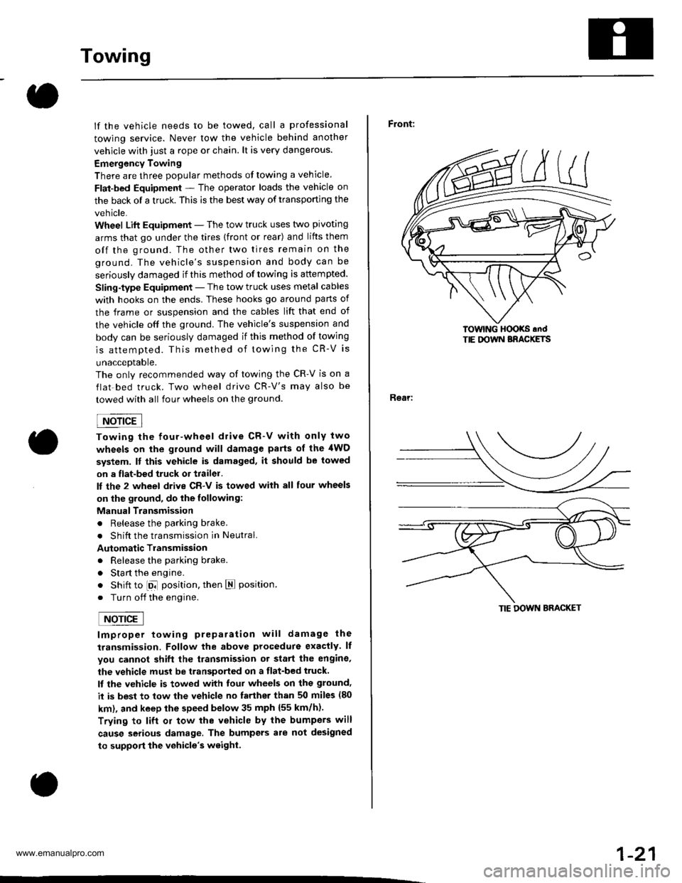
Front:
Rear:
lOwlNG HOOKS .ndTIE DOWN BRACKETS
TIE DOWN BRACKET
1-21
www.emanualpro.com
Page 27 of 1395
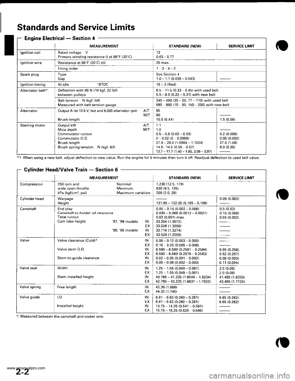
MEASUREMENTSTANDAFD INEWISERVICE LIMIT
lgnition coilRated voltage VPrimary winding resistance 0 at 68'F (20'C)120.63 0.77
lgnition wireBesistance at 68"F (20 C) ktl25 max.
Firing order1 3 4-2
Spark plugTypeGapSee Section 41.0 - 1.1 (0.039 - 0.043)
lgnition timingAt idle BTDC161 2 {Red)
Alternator belt*rDeflection with 98 N {10 kgf, 22 lbf)8.5 11.510.33 0.45)with used belt5.5 - 8.0 (0.22 - 0.31) with new belt
Belt tension N {kgf, lbt)Measured with bek tension gauge340 - 490 {35 - 50, 77 110) with used belt690 880 (70 90, 150 - 200i with new belt
AlternatorOutput A (at 13.5 V, hot and 6,000 alternator rpm AIIM/IBrush length
959010.5 (0.41)1.5 (0.06i
Staning motorOutput kW A/fMica depth MfiCommutator runoutCommutator O.D.Brush lengthBrush spring tension N (kgf, lbf)
1.11.00.5 - 0.8 {0.02 - 0.03)0,0.02 (0 0.0008)27.9 28.0 (1.0984 1.1024)14.0 14.5 (0.55 0.57)13.7 - 17.7 (1.40 - 1.80,3.09 - 3.97)
0.2 (0.008)
0.0s (0.002)
27.0 (1.06)
9.0 (0.35)
Standards and Service Limits
Engine Electrical - Section 4
'1 When using a new belt, ddiust deflection to new value. Run the engine for 5 minutes then turn it of{. Beadiust deflection to used belt value.
Cylinder Head/Valve Train - Section 6
MEASUREMENTSTANDARD {NEW} SERVICE LIMIT
Compression250 rpm and Nominalwide open throttle MinimumkPa (kgflcm'�, psi) Maximum variation
1 ,230 i'12 .5 , 11Al930 (9.s, 135)200 12.0,2al
Cylinder headWarpageHeight131.95 - 132.05 {5.195 - 5.199)0.05 {0.002)
CamshaftEnd playCamshaft to hoider oil clearanceTotal runoutCam lobe height '97,'98 models lNEX'99,'00 models lNEX
0.05 0.1s (0.002 0.006)0.030 - 0.069 (0.0012 - 0.0027)0.03 {0.001)max.33.204 \1.3072133.528 {1.3200)33.1 16 \1 .321 4)33.528 {'1.3200)
0.5 (0.02)
0.15 (0.006)
0.04 (0.002)
Valve clearance (Cold)* lNEXValve stem O.D. lNEXStem'to-guide clearance lNEX
0.08 - 0.12 (0.003 0.005)0.16 0.20 (0.006 - 0.008)6.580 - 6.590 (0.2591 0.2594)6.550 - 6.560 (0.2579 0.2s83)0.02 - 0.05 {0.00t 0.002)0.05 - 0.08 (0.002 0.003)
u* to.rutt6.52lO.257l0.08 {0.003i0.'1t (0.004)
width tNEXStem installed height lNEX
1.25 - 1.55 (0.049 - 0.061)1.25 1.55 (0.049 - 0.061)40.765 - 41.235 {1.6049 1.6234)42.765 - 43.235i'1.6837 - 1.70221
2.0 (0.08)
2.0 (0.08)
41.485 {1.6333}43.485 {1.7120i
Valve springFree length lNEX42.36 (1.668i
44.32 t1 .1 451
Valve guideI,D, INEXInstalled height tNEX
6.61 6.63 10.260 - 0.261)6.61 6.63 {0.260 - 0.261i13.75 - 14.25 10.541 0.561i15.75 - 16.25 {0.620 0.640i
6.6510.26216.65 (0.262i
*: Measured between the camshaft and rocker arm,
2-2
www.emanualpro.com
Page 31 of 1395
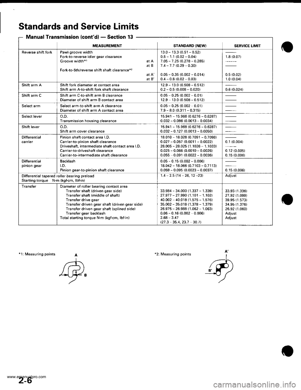
Standards and Service Limits
Manual Transmission {cont'd} - Section 13
11: fuleasuring points A
A
'Ay"
-l-...
_{-P)
A'*2: Measuring points
MEASUREMENTSTANDARO INEW) SERVICE LIMIT
Raverse shift IorkPawl groove widthFork-to-reverse idler gear clearanceGroove width*l at AatBFork-to-5th/reverse shift shaft clearance*'�
at B'
'13.0 - 13.3 (0.5'�j - 0.52)0.5 - 1.1 (0.02 - 0.04)7.O5 - 7.25 i.0.21 4 - 0.24517.4 -7.7 t0.29 0.301
0.05 - 0.35 (0.002 - 0.014)0.4,0.8 (0.02 0.03)
18 (0.07)
0.5 {0.02)1.0 (0.04)
Shift arm AShift fork diameter at contact areaShift arm A-to-shitt tork shaft clearance12.9 - 13.0 (0.508 - 0.512)0.2 - 0.5 (0.008- 0.020)0.6 {0.024i
Shift arm CShift arm C'to-shift arm B clearanceDiameter of shift arm B contact area0.05 0.25 (0.002 0.01)r2.9 - 13.0 (0.508 - 0.512)
Select armSelect arm'to-shift arm A clearanceDiameter of shift arm A contact area0.05 - 0.25 (0.002 0.01)7.9 - 8.0 (0.311 - 0.31s)
Select levero.D.Transmission housing clearance15.94r - 15.968 (0.6276 - 0.6287)0.032 - 0.086 (0.0013 - 0.0034)
Shift levero.D.Sh ift arm cover clearancer5.941 - 15.968 (0.6276 - 0.6287)0.032 - 0.127 (0.0013 - 0.0050)
DifferentialcarnerPinion shaft contact area LD.Carrier-to-pinion shaft clearanceDriveshaft, intermediate shatt contact area LD,Carrier-to-driveshaft clearanceCarrierto-interrnediate shaft clearance
18.010 18.028 (0.7091 - 0.7098)0.027 - 0.057 (0.0011 - 0.0022)28.005 - 28.025 (1.1026, 1.1033)0.025 - 0.066 (0.0010,0.0026)
0.055 - 0.091 10.0022 - 0.0036)
0.1 (0.004)
0.12 {0.005i0.15 (0.006i
Differentialpinion gearBacklasht.D.Pinion gearto-pinion shaft clearance
0.05-0.r5 {0.002 - 0.006)18.042 - 18.066 (0.7103 - 0.7113)0.059 - 0.095 10.0023 - 0.0037)oru ro.ooor
Ditferential tapered roll€r besring preloacStaning torque N.m (kgf.cm, lbl.ini
1.4 2.5i'14 26,12 -231Adjust
TransterDiameter of roller bearing contact areaTransler shaft {driven gear side}Translor shaft {middle of shaft)Transter drive gearTranslor driven gear shaft {driven gear side)Transter driven gear shaft (splined side)Trans{er gear backlashTotalstarting torque N.m (kgicm, lbiin)
33.984 - 34.000 (1.337 - 1.339)21.977 - 27.99011.101 1.102140.002 - 40.01811.575 - 1.576)35.002 - 35.01811.378 - 1.379)26.975, 26.988 (1.062 1.063)0.06 - 0.16 {0.002 0.006)2.64 3.41\21.3,35.4,23.1 30.t|
33.93 (1.336)
27 .92 (1 .O99)39.95 (1.573)
34.95 (1.376)
26.92 (1.060)
AdjustAdjust
2-6
www.emanualpro.com
Page 33 of 1395
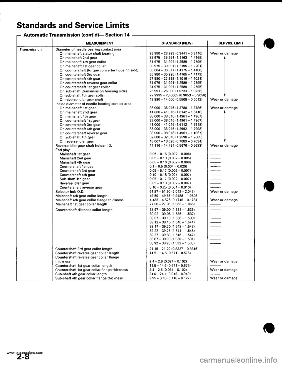
Standards and ServiceLimits
Section 14Automatic Transmission (cont'd)-
MEASUBEMENTSTANDARD {NEW}SERVICE LIMIT
TransmissionDiameter of needle bearing contact areaOn mainshaft stator shaft bearingOn mainshaft 2nd gear
On mainshaft 4th gear collarOn mainshaft 1st gear collarOn countershatt (torque converter housing side)On countershaft 3rd gear
On countershaft 4th gearOn countershaft reverse gear collarOn countershaft 1st gear collarOn sub-shaft {transmission housing sideiOn sub shaft 4th gear collarOn reverse idler gear shaftInside diameter of needle bearing contact areaOn mainshaft 1st gear
On mainshaft 2nd gearOn mainshaft 4th gear
On countershaft 1st gear
On countershaft 3rd gear
On countershaft 4th gear
On countershaft reverse gearOn sub-shaft 4th gear
On reverse idler gearfleverse idler gear shaft holder l.D.End playMainshaft 1st gearMainshaft 2nd gearMainshaft 4th gearCountershaft 1st gearCountershaft 3rd gearCountershaft 4th gear
Sub-shaft 4th gear
Reverse idler gearCountershaft reverse gear
Selector hub O.D.Mainshaft 4th gear collar lengthMainshaft 4th gear collar flange thicknessMainshaft 1st gear collar length
23.980- 23.993 (0.9441 - 0.9446)35.975 35.99'! (1.4163 1.4169)31.975 31.991 (1.2589 1.2595i30.975 - 30.991 11.2195 - 1.2201l'36.004 - 36.017 (1.4175 - 1.4180)35.980 35.996 (1.4165 1.4172)27.980 - 27.993 (1.1016 - 1.1021i31.975- 31.991 (1.2589 -'�j.2595i
31.975- 31.991 (1.2589 - 1.2595)25.991 - 26.000 (1.0233 - 1.0236)22.9935 - 23.006s (0.9053 0.9058)13.990 - r4.000 (0.5508 - 0.5512)
35.000 35.016 (1.3780 1.3786)41.000 - 41.016 (1.6142 - 1.6148)38.000 - 38.016 (1.4961 -'�1.4967)
38.000 - 38.016 (1.496'1 - 1.4967)41.000 41.016 (1.6142 1.6148)33.000 - 33.016 (1.2992 1.2998)38.000 - 38.016 (1.4961 - 1.4967)32.000 - 32.016 (1.2598 - 1.2605)18.007 - 18.020 (0.7089 - 0.7094)14.416 14.434 (0.5676 0.5683)
0.05 - 0.16 {0.002 - 0.006)0.05 - 0.13 (0.002 - 0.005)0.05,0.'16 (0.002 0.006)0.1 0.5 (0.004 0.020)0.05 0.17 {0.002 0.007)0.10 0.18 (0.004 0.007)0.0s 0.17 (0.002 - 0.007)0.05 - 0.18 (0.002 - 0.007)0.10,0.25(0.004 0.010)51.87 - 51.90 (2.042 - 2.043)49.50 - 49.55 (1.9488 - |.9508)4.435 4.525 (0.1746-0.1781)
27.00,27.05 {1.063'1.065i
Wear or damage
Wear or damage
Wear or damage
Wear or damage
il*=lo'. d"'.n"n"
Wear or damage
Countershaft distance collar length38.97 - 39.00 (1.534 - 1.535)39.02 39.05 (1.536, 1.537)39.07 39.10 (1.538 1.539)39.12 - 39.15 (1.540 - 1.541)39.17 - 39.20 (1.542 * 1.543)39.22 - 39.25 11.544 - 1.545)39.27 39.30 1'1.546 - 1.547i38.87 38.90 {1.530 1.531)38.92 38.95 (1.s32 1.533)
Countershaft 3rd gear collar lengthCountershaft reverse gear collar lengthCountershaft reverse gear collar flangethicknessCountershaft 1st gear collar lengthCountershaft lst gear collar flange thicknessSub-shaft 4th gear collar lengthSub shatt 4th gear collar flange thickness
21.15 - 21.20 rc.4327 - 0.4346)14.5, 14.6 (0.57't , 0.575)
2.4 - 2.6 (0.094 - 0.102)14.5 - 14.6 (0.571 - 0.575)2.4 - 2.6 (0.094 - 0.102)24.0 24.1 (0.945 0.949)2.95 - 3.10 (0.116 - 0.122)
Wear or damage
Wear or damage
Wear or damage
2-8
www.emanualpro.com
Page 34 of 1395
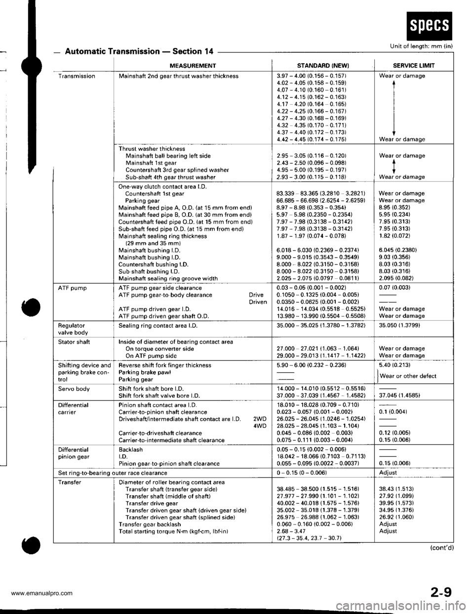
2-9
Automatic Transmission - Section 14
o
Unit of length: mm (in)
o
MEASUREMENTSTANDARD (NEWISERVICE LIMIT
TransmissionMainshaft 2nd gear thrust washer thickness3.97 - 4.00 10.156 - 0.157)4.02 - 4.05 {0.158 - 0.159)4.07 - 4.1010.160 0.161)4.12 - 4.15 (0.162 - 0.163)4.17 4.20 (0.164 0.165)4.22 - 4.25 10.166 - 0.167 )4.27 - 4.30 (0.168 - 0.169)4.32 4.35 (0.170-0.171)
4.37 - 4.40 (0.172 0.173)4.42 - 4.45 (0.174 - 0. r75)
I
I
IWear or damage
Thrust washer thicknessl'rainshaft ball bearing left sideMainshaft 1st gear
Countershaft 3rd gear splined washerSub-shaft 4th gear thrust washer
2.95 3.05 (0.116 0.120)2.43 - 2.50 (0.096 - 0.098)4.9s - 5.00 (0.195 - 0.197)2.93 - 3.00 (0.115 - 0.1181
Wear or damage
tIWear or damage
One-way clutch contact area LD.Countershaft 1st gearParking gearMainshaft feed pipe A, O.D. (at 15 mm trom end)Mainshaft feed pipe B, O.D. (at 30 mm from end)Countershaft teed pipe O.D. lat 15 mm from end)Sub-shaft feed pipe O.D. (at 15 mm from end)Mainshatt sealing ring thickness(29 mm and 35 mm)Mainshaft bushing I.D.Mainshaft bushing l.D.Countershaft bushing l.D.Sub shatt bushing LD.Mainshaft sealing ring groove width
83.339 83.365 (3.2810 3.2821)66.685 - 66.698 (2.6254 - 2.6259)8.97 - 8.98 (0.353 - 0.354)5.97 5.98 {0.2350 - 0.2354)7.97 - 7.98 (0.3138 - 0.3142)7.97 ,7.98 (0.3138 - 0.3142)1.87 - 1.97 (0.074-0.078)
6.018 - 6.030 (0.2369 - 0.2374)9.000 - 9.015 (0.3543 - 0.3549)8.000 - 8.022 (0.3150-0.3158)
8.000 - 8.022 (0.3150 0.3158)2.025 - 2.075 (0.0797 0.0811)
Wear or damageWear or damage8.95 (0.352)
5.95 (0.234)
7.95 (0.313)
7.95 {0.313)1 .42 $.O72)
5.045 (0.2380)
9.03 (0.356)
8.03 (0.316)
8.03 (0.316)
2.095 (0.082)
ATF pumpATF pump gear side clearanceATF pump gear'to body clearance DriveDrivenATF pump driven gear LD.ATF pump driven gear shaft O.D.
0.03 - 0.05 (0.001 - 0.002)0.1050 0.1325 (0.004, 0.005)0.0350 - 0.0625 10.001 - 0.002)14.016* 14.034 (0.5518 0.5525)13.980 - 13.990 {0.5504 0.5508)
0.0710.003)
Wear or damageWear or damage
Regulatorvalve bodySealing ring contact area l.D,35.000 35.025 {1.3780 - 1.3782)35.050 (1.3799)
Stator shaftInside of diameter oI bearing contact areaOn torque convener sideOn ATF pump side2't .o00 27 .021 I '1 .063 , 1 .064)29.000 - 29.01311.r417 1.1422)Wear or damageWear or damage
Shifting device andparking brake con'trol
Reverse shitt fork finger thicknessParking brake pawl
Parking gear
5.90 - 6.00 {0.232,0.236)5.40 (0.213)
lWear or other defect
Servo bodyShift fork shatt bore l.D.Shift fork shatt valve bore l.D.14.000 - 14.010 (0.55'�l2 - 0.5516)37.000 - 37.039 (1.4567 - 1.4582)37.045 (1.4585)
DifferentialcarrierPinion shaft contact area LD.Carrierto-pinion shaft clearanceDriveshafvintermediate shaft contact are l.D. 2WD4WDCarrier to driveshalt clearanceCarrier-to-intermediate shaft clearance
'18.010 - 18.028 10.709 - 0.710)0.023 - 0.057 {0.001 - 0.002}26.025 - 26.045 (1.0246 - 1.0254)28.025 - 28.045 (1.103 - 1.104)0.045 - 0.08610.002 0.003)0.075 - 0.111 10.003- 0.004)
0.r {0.004)
0.12 (0.005)
0.15 (0.006)
Differentialprnron gearBacklasht.D.Pinion gear'to-pinion shaft clearance
0.05 - 0.15 (0.002 - 0.006)18.062 - 18.066 (0.7103 - 0.7113)0.055 - 0.095 10.0022 - 0.0037)otu to.oout
Set ring-to-bearing outer race clearance0 0.15 (0 - 0.006)Adjust
TransferDiameter of roller bearing contact areaTransfer shaft (transfer gear side)Transfer shaft (middle of shaft)Transfer drive gearTransfer driven gear shaft {driven gear side)Transfer driven gear shaft {splined side)Transfer gear backlashTotalstarting torque N.m (kgf.cm, lbf.in)
38.485 38.500 (1.515 - 1.516)27 .917 - 21 .990 |.1.101 - 1.102)40.002 - 40.018 (1.575 - 1.576)35.002 35.018 (1.378 - 1.379)26.975 26.988 (1.062 -'�l.063)
0.060 0.160 (0.002 - 0.006)2.64 - 3.41127.3 - 35.4,23.1 30.71
38.43 (1.513)
27.92 (1.099)
39.95 (1.573)
34.95 (1.376)
26.92 (1.060)
AdiustAdiust
(cont'd)
www.emanualpro.com
Page 51 of 1395
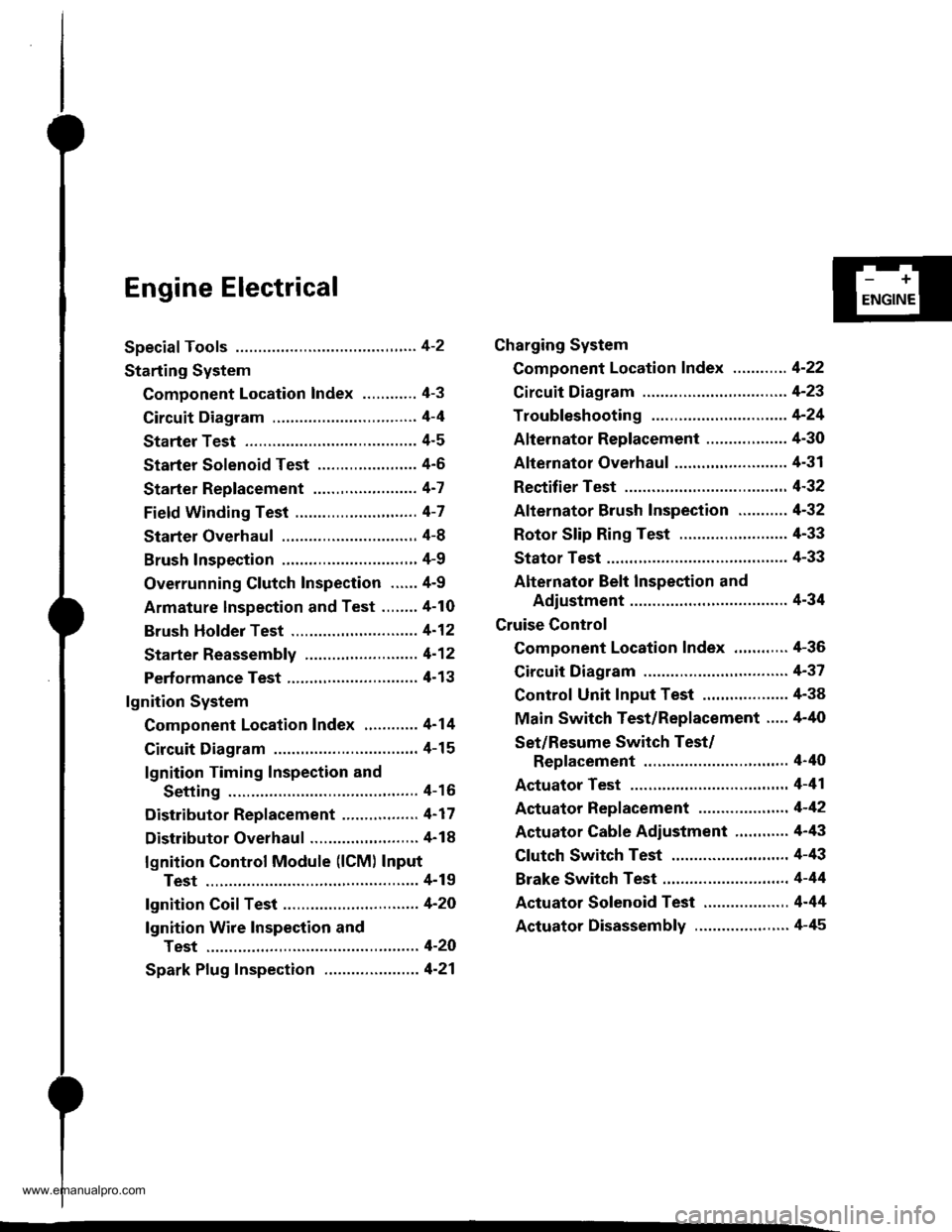
Engine Electrical
Speciaf Tools ............. 4-2
Starting System
Component Location Index ............ 4-3
Circuit Diagram ................................ 4-4
Starter Test ........... 4-5
Starter Solenoid Test ...................... 4'5
Starter Replacement ....................... 4-7
Field Winding Test ........................... 4-7
Starter Overhaul ............................,. 4-8
Brush Inspection ...........................,., 4-9
Overrunning Glutch Inspection ...... 4-9
Armature lnspection and Test ........4-10
Brush Holder Test ............................ 4-12
Starter Reassemb|y ......................... 4-1 2
Perf ormance Test ............................. 4- 1 3
lgnition System
Component Location Index ............ 4-14
Circuit Diagram ................................ 4-15
lgnition Timing Inspection and
Setting .......................................... 4-16
Distributor Replacement ........,........ 4-17
Distributor Overhaul .............,,......... 4-18
lgnition Control Module (lCM) Input
Test ..............................,................ 4-19
fgnition Coil Test .............................. 4-2O
lgnition Wire Inspection and
Test ............................................... 4-20
Spark Plug Inspection ..................... 4-21
-+
ENGINE
Charging System
Component Location Index ............ 4-22
Circuit Diagram ....................,........... 4-23
Troubleshooting .............................. 4-24
Alternator Replacement ..........,....... 4-30
Alternator Overhaul .......,,................ 4-31
Rectifier Test .........4-32
Alternator Brush Inspection ........... 4-32
Rotor Slip Ring Test ........................ 4-33
Stator Test ............. 4-33
Alternator Belt Inspection and
Adiustment ........4-34
Gruise Control
Component Location Index .,,,........ 4-36
Circuit Diagram ................................ 4-37
Control Unit Input Test ................... 4-38
Main Switch Test/Replacement ..... 4-40
Set/Resume Switch Test/
Replacement .......................,........ 4'40
Actuator Test ....,,., 4-41
Actuator Replacement ...............,.... 4-42
Actuator Cable Adiustment ............ 4-43
Clutch Switch Test .......................... 4-43
Brake Switch Test .................. .......... 4-44
Actuator Solenoid Test .............. ...,. 4-44
Actuator Disassembly ..................... 4-45
www.emanualpro.com
Page 56 of 1395
Starting System
Starter Test (cont'dl
Check lor Wear and D8mage
The starter should crank the engine smoothly and
steadily. lf the staner engages, but cranks the engine
erratically, remove it, and inspect the starter drive gear
and torque converter ring gear or flywheel ring gear for
oamage.
Check the drive gear overrunning clutch for binding or
slipping when the armature is rotated with the drive
gear held. lf damaged, replace the gears.
Check Cranking Voltage and Current Draw
Cranking voltage should be no less than 8.7 volts on Ay'T
models, and 8.0 volts on M/T moders.
Current draw should be no more than 230 amperes on
A,/T models, and 200 amperes on M/T models.
lf cranking voltage is too low, or current draw too high,
check for:
. dead or low battery.
a open circuit in starter armature commutator seg,
ments.
. starter armature dragging.
. shorted armature winding.
. excessive drag in engine.
Check Cranking rpm
Engine speed during cranking should be above 100 rpm.
lf speed is too low, check for:
a loose baftery or starter terminals.
. excesslvely worn staner brushes
. open circuit in commutator segments.
. dirty or damaged helical splines or drive gear.
a defective drive gear overrunning clutch.
Check Starter Disengagement
With the shift lever in @ or @ position (A,iT) or with the
clutch pedal depressed {M/T). turn the ignition switch to
START (lll). and release to ON (ll).
The starter drive gear should disengage from the torque
converter ring gear or flywheel ring gear when you
release the key.
lf the drive gear hangs up on the torque converter ring
gear or flywheel ring gear, check for
. solenoid plunger and switch malfunction.
. dirty drive gear assembly or damaged overrunning
clutch.
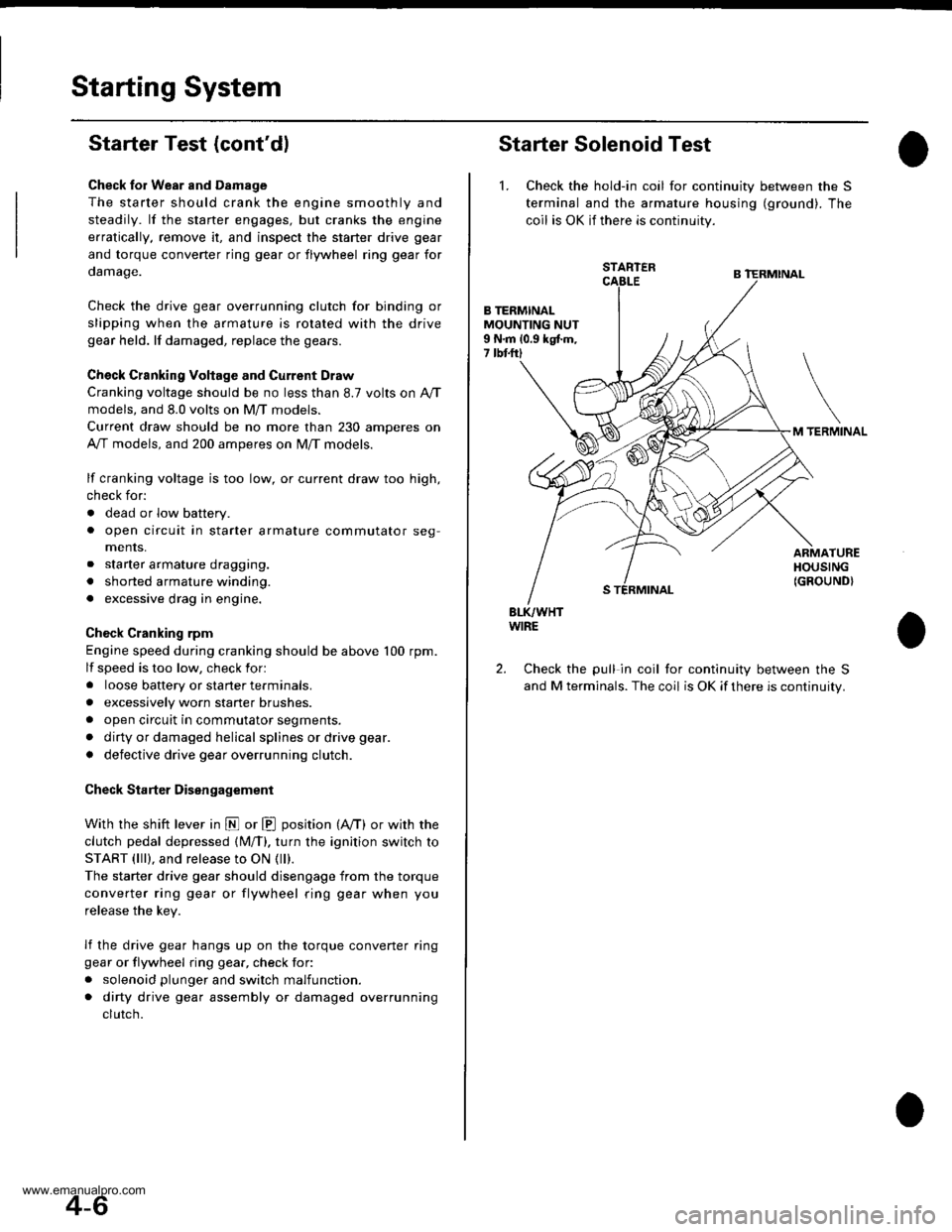
Starter Solenoid Test
1. Check the hold-in coil for continuity between the S
terminal and lhe armature housing (ground). The
coil is OK if there is continuity.
STARTER
B TERMINALMOUNTING NUT9 N.m 10.9 kgtm,7 tbtftl
TERMINAL
ARMATUREHOUSING(GROUND}
BLK/WHTWIRE
Check the pull in coil for continuity between the S
and M terminals. The coil is OK if there is continuity.
2.
4-6
www.emanualpro.com
Page 57 of 1395
RE
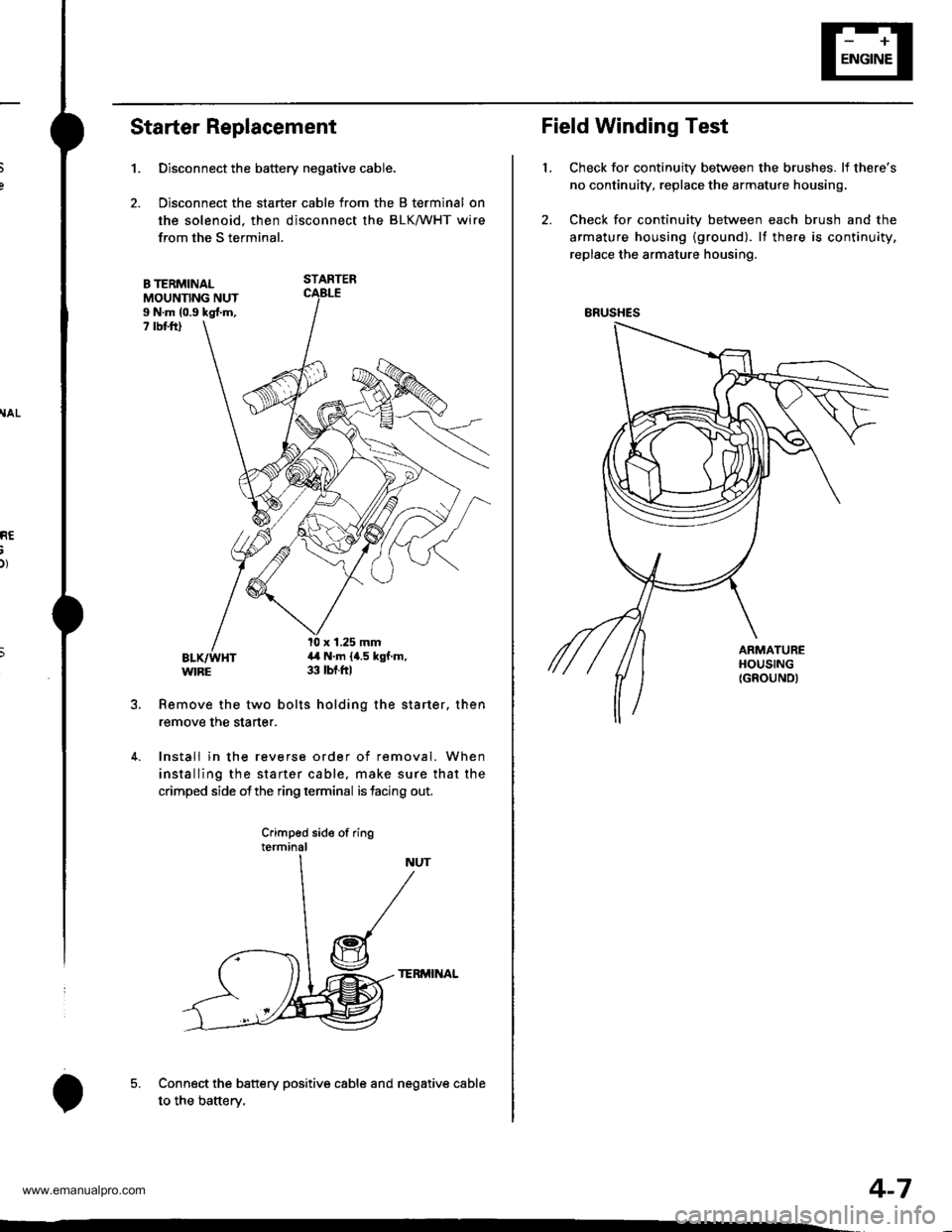
Starter Replacement
1.
B TERMINALMOUNNNG NUTI N.m (0.9 kgl.m,7 rbt ftl
Remove the two bolts holding the starter. then
remove the starter.
4. Install in the reverse order of removal. When
installing the starter cable, make sure that the
crimped side ofthe ring terminal is facing out,
Crimped side of ringterminal
TERMINAL
Connect the battery positive cable and negative cable
to the batterv.
Disconnect the battery negative cable.
Disconnect the starter cable from the B terminal on
the solenoid. then disconnect the BLK/WHT wire
from the S terminal.
STARTER
l0 x 1.25 mm4,1 N.m {4.5 kgf.m,33 tbt.ftl
5.
o
Field Winding Test
Check for continuity between the brushes. lf there's
no continuity, replace the armature housing,
Check for continuity between each brush and the
armature housing {ground). lf there is continuity.
replace the armature housing.
t.
ERUSHES
4-7
www.emanualpro.com