Arm HONDA CR-V 1998 RD1-RD3 / 1.G User Guide
[x] Cancel search | Manufacturer: HONDA, Model Year: 1998, Model line: CR-V, Model: HONDA CR-V 1998 RD1-RD3 / 1.GPages: 1395, PDF Size: 35.62 MB
Page 58 of 1395
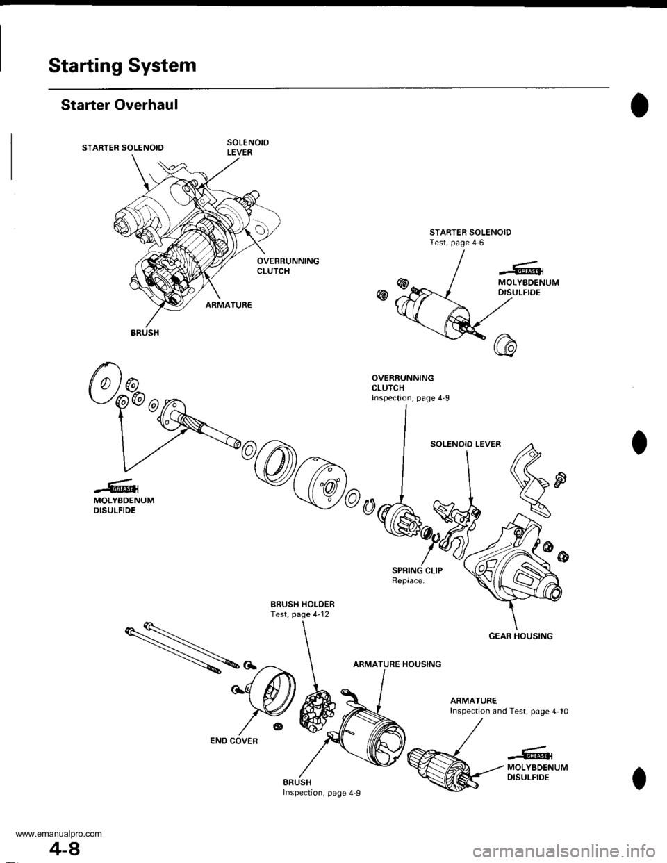
Starting System
Starter Overhaul
STARTER SOLENOID
STARTER SOLENOIDTest, page 4 6
OVEBRUNNINGCLUTCH
w
-6^lMOLYBDENUMDISULFIDE
SPRING CLIPReplace.
BBUSH HOLDERTest, page 4-12
ARMATURE HOUSING
ARMATUREInspection and Test. page 4-10
..'...:|@{MOLYBDENUMDISULFIDEBAUSHInsPeclon, page 4-9
ARUSH
GEAR HOUSING
4-A
END COVER
www.emanualpro.com
Page 59 of 1395
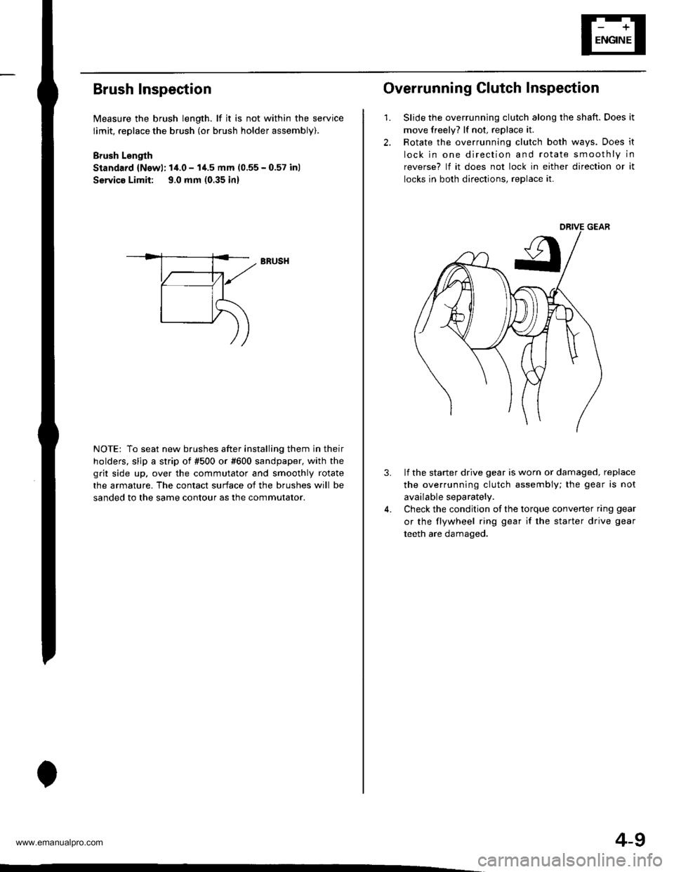
Brush Inspection
Measure the brush length. lf it is not within the service
limit, replace the brush (or brush holder assembly).
Brush Lsngth
Standard {Newl: 14.0 - I'1.5 mm (0.55 - 0.57 inl
Servico Limit: 9.0 mm (0.35 in)
NOTE: To seat new brushes after installing them in their
holders. slip a strip of #500 or #600 sandpaper, with the
grit side up, over the commutator and smoothly rotate
the armature. The contact surface of the brushes will be
sanded to the same contour as the commutator.
BRUSH
4-9
2.
1.
Overrunning Clutch Inspection
Slide the overrunning clutch along the shaft. Does it
move freely? lf not, replace it.
Rotate the overrunning clutch both ways. Does it
lock in one direction and rotate smoothly in
reverse? lf it does not lock in either direction or it
locks in both directions, reDlace it.
3.lf the starter drive gear is worn or damaged, replace
the overrunning clutch assembly; the gear is not
available separately.
Check the condition of the torque converter ring gear
or the flywheel ring gear if the starter drive gear
teeth are damaged.
www.emanualpro.com
Page 60 of 1395
Starting System
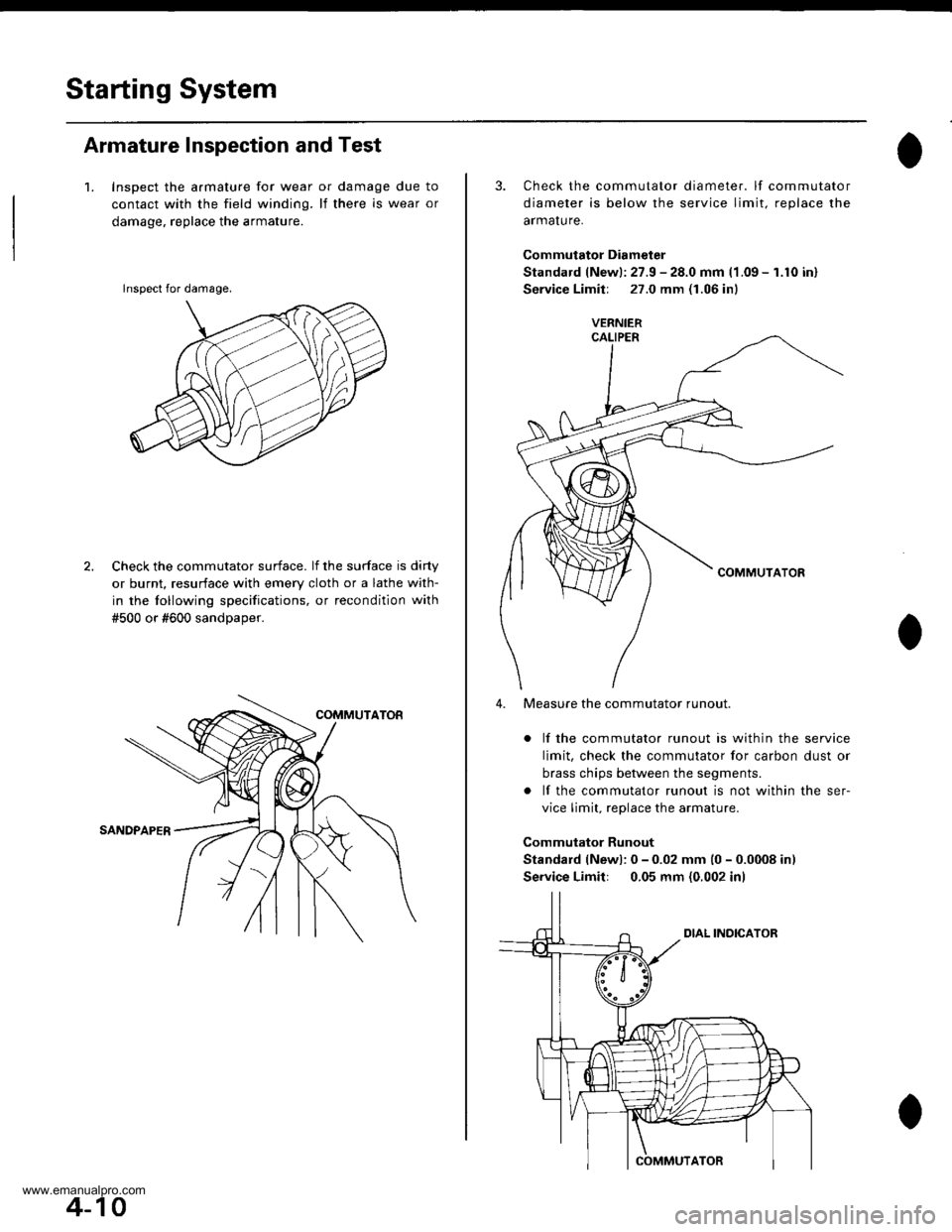
Armature Inspection and Test
1. Inspect the armature for wear or damage due to
contact with the field winding. lf there is wear or
damage. replace the armature.
Check the commutator surface. lf the surface is dirty
or burnt, resurface with emery cloth or a lathe with-
in the tollowing specifications, or recondition with
#500 or #600 sandDaoer.
lnspect for damage.
4-10
3. Check the commutator diameter. lf commutator
diameter is below the service limit, reolace the
armalure.
Commutator Diameter
Standard (Newl: 27.9 - 28.0 mm (1.09 - 1.10 in)
Service Limilr 27.0 mm (1.06 inl
lf the commutator runout is within the service
limit, check the commutator for carbon dust or
brass chips between the segments.
lf the commutator runout is not within the ser-
vice limit, replace the armature.
Commutator Runout
Standard (Newl: 0 - 0.02 mm (0 - 0.0008 in)
Service Limit: 0.05 mm {0,002 inl
4. Measure the commutator runout.
www.emanualpro.com
Page 61 of 1395
I
NOT GOOD
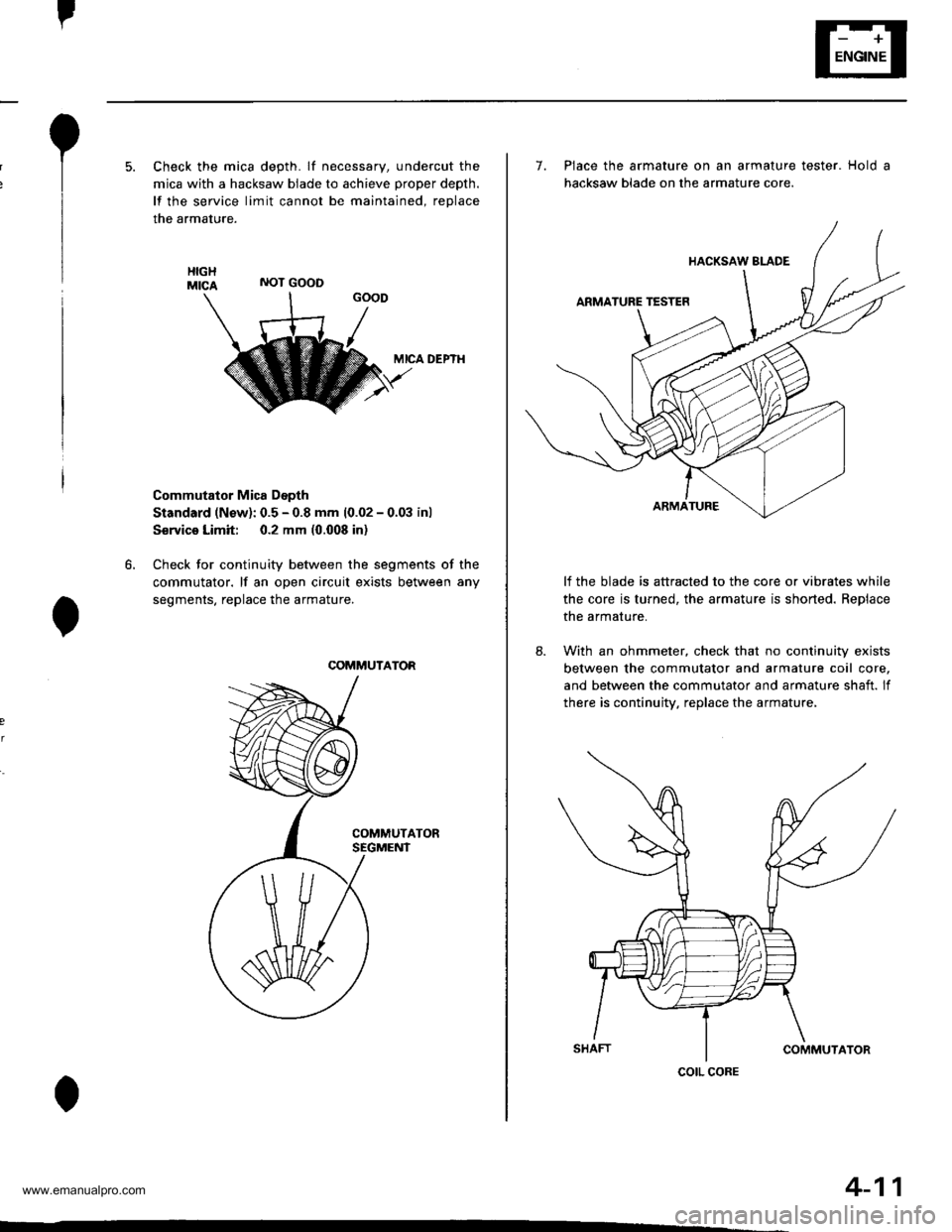
5. Check the mica depth. lf necessary, undercut the
mica with a hacksaw blade to achieve proper depth.
lf the service limit cannot be maintained, reDlace
the armature.
MICA DEPTI{
Commutator Mica Depth
Standard (Nsw): 0.5 - 0.8 mm 10.02 - 0.03 inl
Servico Limit: 0.2 mm (0.008 in)
Check for continuity between the segments of the
commutator. lf an open circuit exists between any
segments. replace the armature.
6.
COMMUTATOR
4-11
7. Place the armature on an armature tester. Hold a
hacksaw blade on the armature core.
lf the blade is attracted to the core or vibrates while
the core is turned. the armature is shorted. Replace
the armature.
8. With an ohmmeter, check that no continuity exists
between the commutator and armature coil core,
and between the commutator and armature shaft. lf
there is continuity. replace the armature,
cotL coRE
www.emanualpro.com
Page 62 of 1395
Starting System
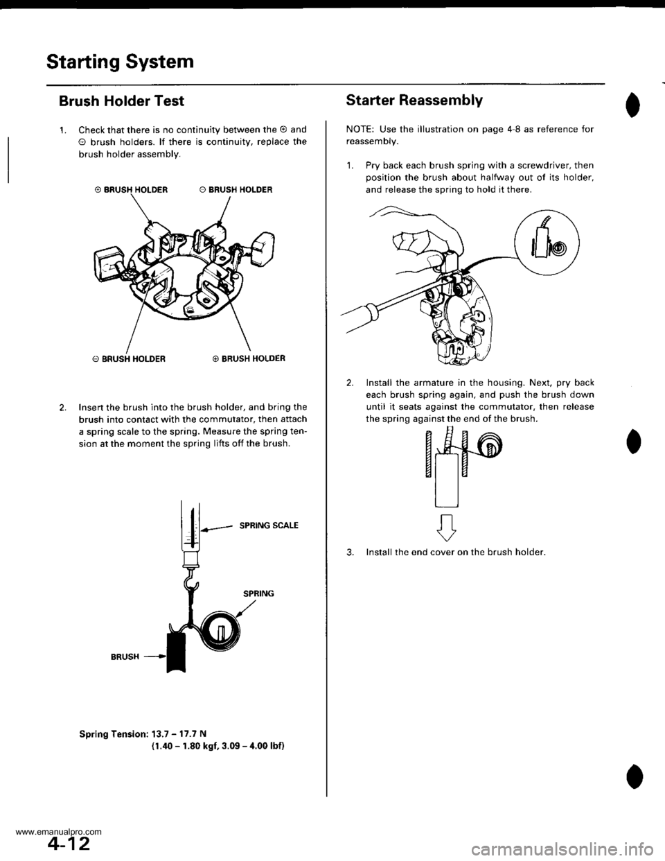
Brush Holder Test
1. Check that there is no continuity between the O and
O brush holders. lf there is continuitv, replace the
brush holder assembly.
O BRUSH HOLDER@ BRUSH HOLDER
Insert the brush into the brush holder, and bring the
brush into contact with the commutator, then attach
a spring scale to the spring. Measure the spring ten-
sion at the moment the spring lifts off the brush.
SPRING SCALE
Spring Tension: 13.7 - 17.7 N
(1.40 - 1.80 kgf, 3.09 - 4.00 lbf)
4-12
Starter Reassembly
NOTE: Use the illustration on page 4I as reference for
reassemDty.
1. Pry back each brush spring with a screwdriver, then
position the brush about halfway out ol its holder,
and release the spring to hold it there.
2. Install the armature in the housing. Next, pry back
each brush spring again, and push the brush down
until it seats against the commutator, then release
the spring against the end of the brush.
- E^
F*4#-@
6t taal la
tlll
3. Install the endon the brush holder.
ft
cover
www.emanualpro.com
Page 104 of 1395
Engine RemovaUlnstallation
OOI{TROL PI
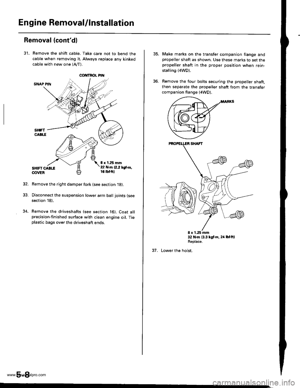
Removal (cont'dl
31. Remove the shift cable. Take care not to bend the
cable when removing it. Always replace any kinked
cable with new one (Afl-).
SNAP PIN
sHtFT CABttOOVEB
8 x 1.25 mmt2 N.m 12.2 lgtr'l'',,16 tbf.ftl
Remove the right damper fork (see section 18).
Disconnect the suspension lower arm ball joints (see
section 18),
Remove the driveshafts (see section t6). Coat allprecision-finished surface with clean engine oil. Tieplastic bags over the driveshaft ends.
5-8
34.
Make marks on the transfer companion flange andpropeller shaft as shown. Use these marks to set thepropeller shaft in the proper position when rein-
stalling (4WD).
Remove the four bolts securing the propeller shaft,then separate the propeller shaft from the transfer
companion flange (4WD).
E x 1.25 mm32 N.m 13.3 lgt.m, 24 lbt'ftlRepl€ce.
37. Lower the hoist,
www.emanualpro.com
Page 118 of 1395
Valve Seals
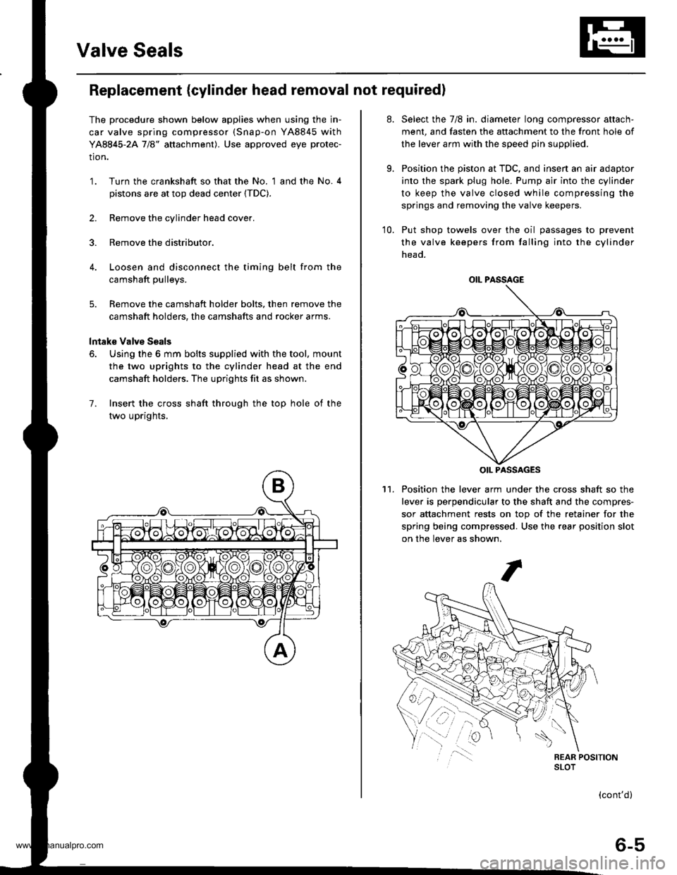
Replacement (cylinder head removal not required)
The procedure shown below applies when using the in-
car valve spring compressor (Snap-on YA8845 with
YA8845-2A 7/8" auachment). Use approved eye protec-
tion.
1. Turn the crankshaft so that the No. 1 and the No. 4
pistons are at top dead center (TDC).
2. Remove the cylinder head cover.
3. Remove the distributor.
4. Loosen and disconnect the timing belt from the
camshaft pulleys.
5. Remove the camshaft holder bolts. then remove the
camshaft holders, the camshafts and rocker arms.
lntake Valve Seals
6. Using the 6 mm bolts supplied with the tool, mount
the two uprights to the cylinder head at the end
camshaft holders. The uprights fit as shown.
7. Insert the cross shaft through the top hole of the
two uprights,
at.
9.
Select the 7/8 in. diameter long compressor attach-
ment, and fasten the attachment to the front hole of
the lever arm with the speed pin supplied.
Position the piston at TDC, and insen an air adaptor
into the spark plug hole. Pump air into the cylinder
to keep the valve closed while compressing the
springs and removing the valve keepers.
10. Put shop towels over the oil passages to prevent
the valve keepers from falling into the cylinder
head.
Position the lever arm under the cross shaft so the
lever is perpendicular to the shaft and the compres-
sor attachment rests on top of the retainer for the
spring being compressed. Use the rear position slot
on the lever as shown,
't1.
OIL PASSAGE
OIL PASSAGES
(cont'd)
6-5
www.emanualpro.com
Page 119 of 1395
Valve Seals
12.
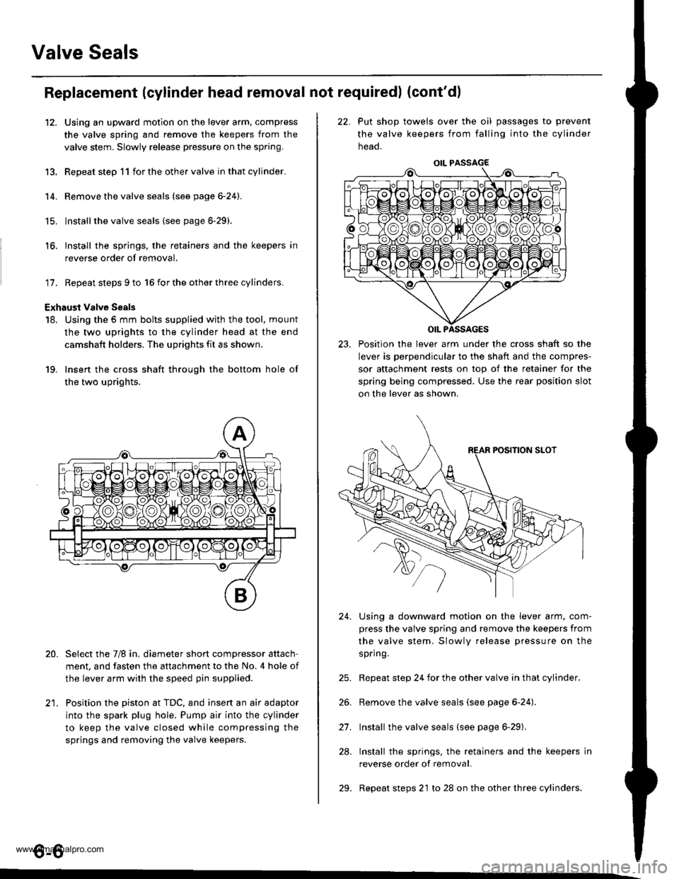
Replacement (cylinder head removal not requiredl (cont'dl
Using an upward motion on the lever arm, compress
the valve spring and remove the keepers from the
valve stem. Slowly release pressure on the spring.
Repeat step 11 for the other valve in that cylinder.
Remove the valve seals (see page 6-24).
Installthe valve seals (see page 6-29).
lnstall the springs, the retainers and the keepers in
reverse order of removal.
'17. Repeat steps 9 to 16 for the other three cylinders.
Exhaust valve Seals
18. Using the 5 mm bolts supplied with the tool, mount
the two uprights to the cylinder head at the end
camshaft holders. The uprights fit as shown.
19. Insert the cross shaft through the bottom hole of
the two uprights.
Select the 7/8 in. diameter short compressor attach
ment, and fasten the attachment to the No. 4 hole of
the lever arm with the speed pin supplied.
Position the piston at TDC, and insert an air adaptor
into the spark plug hole. Pump air into the cylinder
to keep the valve closed while compressing the
springs and removing the valve keepers.
13.
14.
15.
16.
20.
t1
22. Put shop towels over the oil passages to prevent
the valve keepers from falling into the cylinder
neao.
23. Position the lever arm under the cross shaft so the
lever is perpendicular to the shaft and the compres-
sor attachment rests on top of the retainer for the
spring being compressed. Use the rear position slot
on the lever as shown.
Using a downward motion on the lever arm, com-
press the valve spring and remove the keepers from
the valve stem. Slowly release pressure on the
spring.
Repeat step 24 for the other valve in that cylinder.
Remove the valve seals (see page 6-24).
Install the valve seals (see page 6-29).
Install the springs, the retainers and the keepers in
reverse order of removal.
Repeat steps 21 to 28 on the other three cylinders.
24.
21.
28.
29.
o-o
www.emanualpro.com
Page 134 of 1395
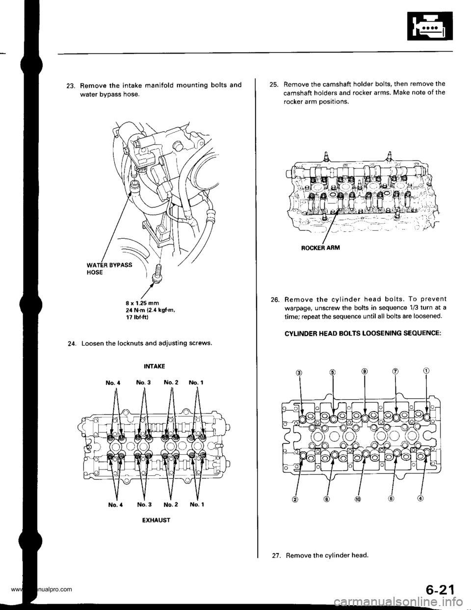
23. Remove the intake manifold mounting bolts and
water bvDass hose.
8 x 1.25 mm2,1 N.m 12.4 kgt.m,17 tbf.ft)
24. Loosen the locknuts and adjusting screws,
INTAKE
No.3 No.2 No. 1
No.3 No.2 No. 1
EXHAUST
No. 4
27. Remove the cylinder head.
6-21
25. Remove the camshaft holder bolts, then remove the
camshaft holders and rocker arms. Make note of the
rocker arm Dositions.
26. Remove the cylinder head bolts. To prevent
warpage, unscrew the bolts in sequence 1/3 turn at a
time; repeat the sequence until all bolts are loosened.
CYLINDER HEAD BOLTS LOOSENING SEOUENCE:
ROCKER ARM
www.emanualpro.com
Page 135 of 1395
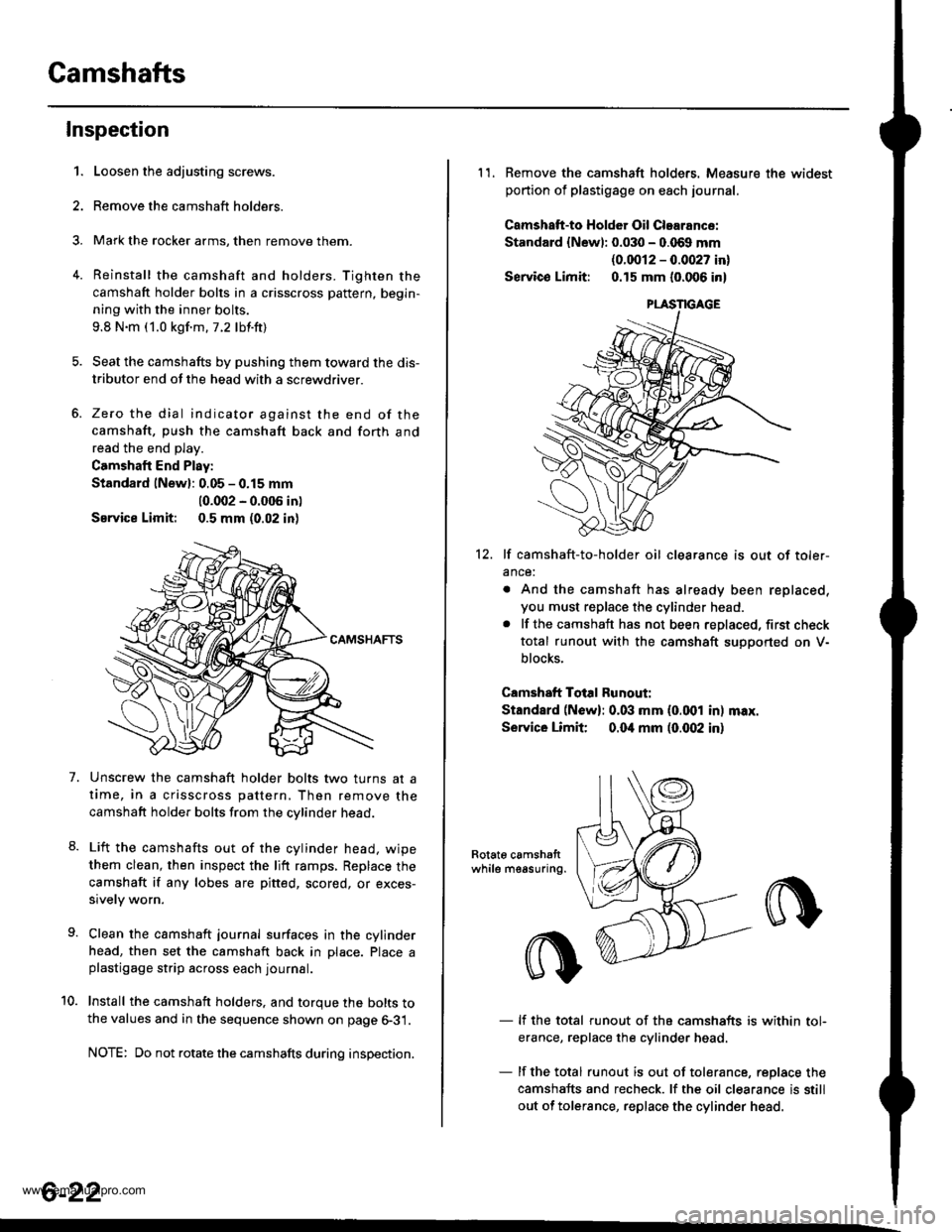
Camshafts
4.
Inspection
1.
7.
Loosen the adjusting screws.
Remove the camshaft holders.
Mark the rocker arms, then remove them.
Reinstall the camshaft and holders. Tighten the
camshaft holder bolts in a crisscross pattern, begin-
ning with the inner bolts.
9.8 N.m (1.0 kgf.m.7.2 lbf.ft)
Seat the camshafts by pushing them toward the dis-
tributor end of the head with a screwdriver.
Zero the dial indicator against the end of the
camshaft, push the camshaft back and forth and
read the end play.
Camshaft End Play:
Standard lNewl: 0.05 - 0.15 mm
10.002 - 0.005 in)
Service Limit: 0.5 mm (0.02 in)
Unscrew the camshaft holder bolts two turns at a
time, in a crisscross pattern, Then remove the
camshaft holder bolts from the cvlinder head.
Lift the camshafts out of the cylinder head. wipe
them clean, then inspect the lift ramps, Replace the
camshaft if any lobes are pitted, scored, or exces-
sively worn.
Clean the camshaft journal surfaces in the cylinder
head, then set the camshaft back in Dlace. Place aplastigage strip across each journal.
Install the camshaft holders. and torque the bolts tothe values and in the sequence shown on page 6-31.
NOTE: Do not rotate the camshafts during inspection.
8.
10.
6-22
11. Remove the camshaft holders. Measure the widest
portion of plastigage on each journal.
Camshatt-to HoldGr Oil Clearance:
Standard {Newl: 0.030 - 0.069 mm
{0.0012 - 0.0027 in}
Servico Limit: 0.15 mm (0.006 in)
12. lf camshaft-to-holder oil clearance is out of toler-
ance:
. And the camshaft has already been replaced,
you must replace the cylinder head.. lf the camshaft has not been replaced, first check
total runout with the camshaft suoDorted on V-
blocks.
Camshaft Total Runout:
Standard (N6w): 0.03 mm (0.001 in) max.
Service Limit 0.04 mm (0.(X)2 in)
Rotat6 camshattwhile measuring.
- lf the total runout of the camshafts is within tol-
erance, replace the cylinder head
- lf the total runout is out of tolerance, replace the
camshafts and recheck. lf the oil clearance is still
out of tolerance, replace the cylinder head.
www.emanualpro.com