Arm HONDA CR-V 1998 RD1-RD3 / 1.G Owner's Guide
[x] Cancel search | Manufacturer: HONDA, Model Year: 1998, Model line: CR-V, Model: HONDA CR-V 1998 RD1-RD3 / 1.GPages: 1395, PDF Size: 35.62 MB
Page 297 of 1395
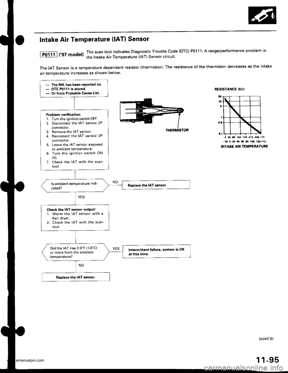
The IAT Sensor is a temperature dependant resistor (thermistor). The resistance of the thermistor decreases as the intake
air temDerature increases as shown below
RESISTANCE IKOI
Intake Air Temperature (lAT) Sensor
1P0111 | ('97 model)The scan tool indicates Diagnostic Trouble code (DTC) P0111: A ranoe/performance problem in
the lntake Air TemDerature (lAT) Sensor circuit.
. 3' aa ro. r?a arl ,.t r.fl20 0 to ao ao aa ioo t2otocl
INTAKE AIB TEMPERATURE
- The MIL has been reported on.- DTC P0111 is stored.- Or lrom Probable Cause List.
Problem vetification:1. Turn the ignition switch OFF.
2. Disconnect the IAT sensor 2P
connector,3. Remove the IAT sensor.4. Reconnect the IAT sensor 2P
connector,5. Leave the IAT sensor etposedto ambient temPerature.6. Turn the ignition switch ON
flr).7. check the IAT with the scan
tool-
R€place the IAT son3or.
Check the IAT sensor output:1. Warm the IAT sensor with ahair dryer.2. Check the IAT with the scan
tool.
Did the IAT rise 2.0'F (1.0'C)
or more from the ambienttemperature?
Intermittent f.ilure, aY3tem is OKai this tim6.
Replace the IAT sensor.
(cont'd)
1 1-95
www.emanualpro.com
Page 298 of 1395
PGM-FI System
Intake Air Temperature (lAT) Sensor (cont'dl
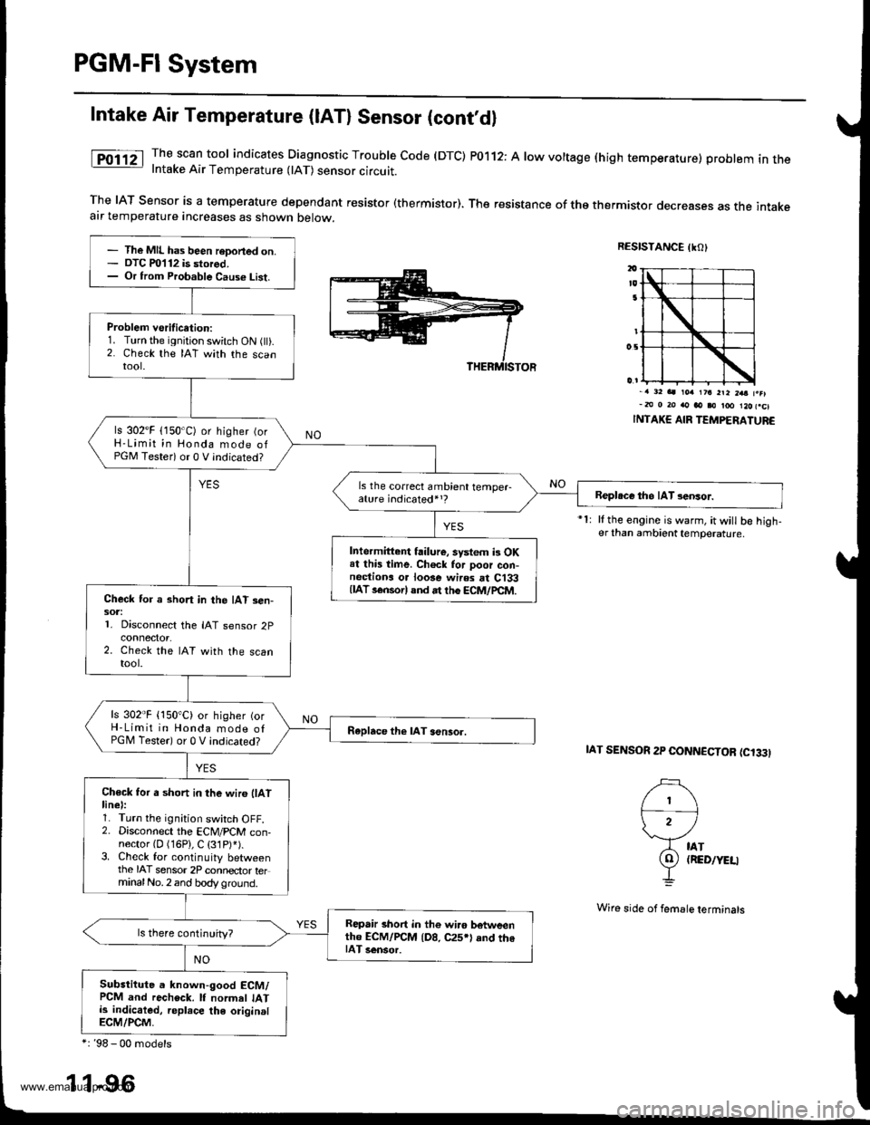
The scan tool indicates Diagnostic Trouble code (DTC) P0112: A low voltage (high temperature) problem in theIntake Air Temperature 0AT) sensor circuit.
The IAT Sensor is a temperature dependant resistor (thermistor). The resistance of tho thermistor decreases as the intakeair temperature increases as shown below.
RESISTANCE IKO)
i')
)2 /
A tAr
9) (RED/YEU
-L
-. 32 aa rorr 1?a 2ra 2aa f.el-m 0 20 rto ao i0 too l2ofcl
INTAKE AIR TEMPERATUR€
It the engine is warm, it will b€ high-er than ambient temperature.
IAT SENSOR 2P CONNCCTOR (C'33I
- The MIL has been reDoned on.- OTC m112 is stored,- Or from Probable Caus€ List.
Problem vsrification:1. Turn the ignition switch ON flt).2. Check the IAT with the scantool.
ls 302'F (150'C) or higher (orH-Limit in Honda mode ofPGM Testeri or 0 V indicated?
ls the correct ambient temper-ature indicated,,?Beploce tho IAT sensor.
Intermittent failure, system i3 OKat this time. Ch6ck for poor con-nectiona o. loose wires rt C133{lAT s€nsorl and rt th6 ECM/pCtr4.Check for a short in the IAT sen-sot:1. Disconnect the IAT sensor 2p
2. Check the IAT with the scantool.
ls 302"F {150"C) or higher {orH-Limit in Honda mode ofPGM Tester) or 0 V indicated?Raplace the lAT aensor.
Ch€ck for a short in the wir6 llAtlinel:1. Turn the ignition switch OFF.2. Disconnect the ECM/PCM con-nector {D (16P}, C (31P)').3. Check for continuity betweenthe IAT sensor 2P connector terminalNo.2 and body ground.
Repair short in the wi.o botweenth6 ECM/rcM {D8, C25*l and th6IAT 3ensor.
Substitute a known-good ECM/PCM and recheck. lf normel IATis indicaled, replace the originalECM/PCM,
*: '98 - 00 models
1 1-96
Wi16 side of femsle terminals
www.emanualpro.com
Page 307 of 1395
'98 - 00 model3:
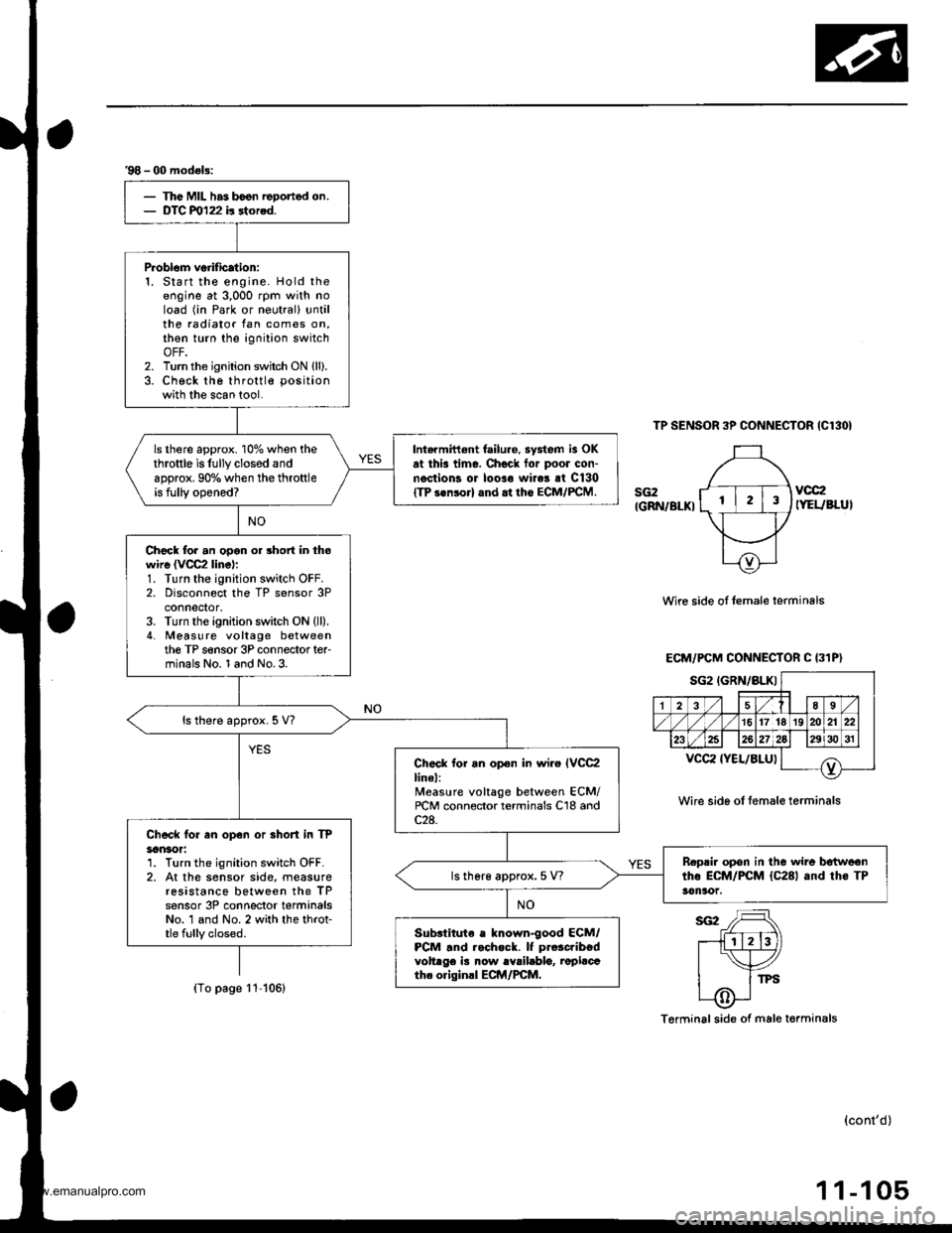
The MIL has boon reDortod on.DTC m122 b rtorod.
P.oblom veiification:1. Start the engine. Hold theengine at 3,000 rpm with noload (in Park or neutral) untilthe radiator tan comes on,then turn the ignition switchOFF.2. Turn the ignition switch ON lll).3. Check the throttle position
with the scan tool.
ls there approx. 10% when thethrottle is fully closed andapprox. 90% when the throttleis fully opened?
Intarmittent failure. system is OKat thia time. Check for poor con-n€ctions or loolo wires rt C130ITP s.nsorl and.t the ECM/FCM.
Check for an opon or short in thowire {VCC2 linel:1. Turn the ignition switch OFF.2. Disconnect the TP sensor 3Pconnedor,3. Turn the ignition switch ON (ll).
4. Meas! re voltage betweenthe TP s€nsor 3P connector ter-minals No. 1 and No.3.
ls there approx. 5 V?
Check lor an opon in wiro IVCC2linel:Measure voltage between ECM/rcM connector terminals C'18 andc2a.Chock for en op€n or Bhort in TP3an30r:1. Turn the ignition switch OFF.2. At the sensor side, measureresistance between the TPsensor 3P conneclor terminalsNo. 1 and No. 2 with the throt-tle fully closed.
B.psir opon in the wire b€{woontho ECM/PCM {C281 and th6 TP3en!xtt.ls lher€ approx. 5 V?
Subslitute e known-good ECM/PCM .nd r.chock. lf pro3cribedvoltrge iB now rYrilablo, replacath. originll ECM/PCM.
TP SENSOR 3P CONNECTOR {C130}
sG2IGRN/BLKI
vcc2IYEUBLUI
Wire side oI Iemale lerminals
Wire sid6 of temale terminals
Terminal side of male torminals
(cont'd)
1 1-105
ECM/PCM CONNECTOR C (31P}
sG2IGRN/BLKIa-,l 18 sl./|135
/1617lrs]zolzr zzl
232527)gJ lzgi3o sr I
T^vccz {YEL/8LUl
(To page 11-106)
www.emanualpro.com
Page 309 of 1395
![HONDA CR-V 1998 RD1-RD3 / 1.G Owners Guide
The scan tool indicates Diagnostic Trouble Code (DTC) P0123: A high voltage problem in the Throttle Position
(TP) sensor circuit.
TP SENSOR 3P @]{NECTOR IC13O}
sG2(GnN/Br.XlvocrtYEt /8LU)
{GBIT/BLKI
HONDA CR-V 1998 RD1-RD3 / 1.G Owners Guide
The scan tool indicates Diagnostic Trouble Code (DTC) P0123: A high voltage problem in the Throttle Position
(TP) sensor circuit.
TP SENSOR 3P @]{NECTOR IC13O}
sG2(GnN/Br.XlvocrtYEt /8LU)
{GBIT/BLKI](/img/13/5778/w960_5778-308.png)
The scan tool indicates Diagnostic Trouble Code (DTC) P0123: A high voltage problem in the Throttle Position
(TP) sensor circuit.
TP SENSOR 3P @]{NECTOR IC13O}
sG2(GnN/Br.XlvocrtYEt /8LU)
{GBIT/BLKI
(cont'd)
11-107
Wiro side of fom.le terminals
PCM CON'{ECTOF D I16PI
Wire side ot female terhinals
The MIL hlr br€n r.9ort.d on.DTC P0123 ir stored.
Pioblom vorificltion:1. Start the ongin6. Hold th€ongine at 3,000 rpm with noload {in Park or neutral) untilth6 radiator fan comes on.then turn the ignition switchOFF,2. Turn the ignition switch ON (ll).
3. Check the throttle position
with the scan tool.
Intarmittant tailuro, ryrtern b OKat this timo. Chock lor poor con-nections or loo3o wir€3 at C130
ITP 3orcorl .nd at tho ECM/FCM.
ls there spprox. 1oyo when thothrottle is Iully closed andapprox.90% when the throttleis tully open€d?
Choct toJ an opcn in th6 TP s6n-3t']:1. Turn the ignition switch OFF.2. Disconnect the TP sensor 3Pconnectol,3. Turn the ignition switch ON (ll).
4. At the wir6 harnoss side, mea-suro voltage betweon thg TPsensor 3P connector t€rminalsNo. 1 and No.3.
ls there approx.5 V?
Chack for an oDan in tha wira(SG2 linel:M6asu16 voltage b6tween PCMconn€ctor terminals Dl0 and D'! 1.
R.pai. opcn in tha wira botwcontho PcM {o111 rnd the TP 3en-3('t,
ls there approx. 5 V?
('97 model)
(To page 11-108)
www.emanualpro.com
Page 339 of 1395
Barometric Pressure (BARO) Sensor
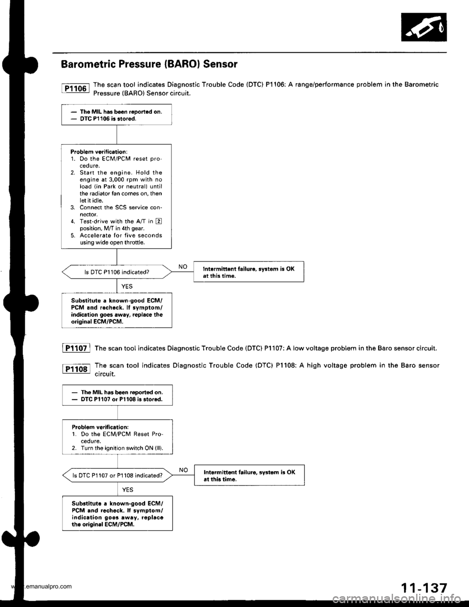
The scan tool indicates Diagnostic Trouble Code (DTC) P1106: A range/performsnce problem in the Barometric
Pressure {BARO) Sensor circuit.
The MIL has been reDorted on.OTC Pl106 b slored.
Problem ve.ification:1. Oo the ECM/PCM reset pro'
ceoure.2. Start the engine. Hold theengine at 3,000 rpm with noload (;n Park or neutral) untilthe radiator lan comes on, thenlet it idle.3. Connect the SCS service con-nector,4. Test'drive with the A/T in Eposition, M/T in 4th gear.
5. Accelerate Ior five secondsusing wide open throttle.
Intermittent fsilure, sy3tom i5 OKat this time.ls DTC P1106 indicated?
Substitute a known-good ECM/PCM .nd recheck. It symptom/indication goes away, replace theorigioal ECM/PCM.
fTiloz l
tP11o8l
The scan tool indicates Diagnostic Trouble Code (DTC) P1107: A low
The scan tool indicates Diagnostic Trouble Code (DTC) Pl108: A
circuit.
voltage problem in the Baro sensor circuit.
high voltage problem in the Baro sensor
- The MIL h.3 b€en roport€d on.- OTC Pl10? or Pl108 i3 stored.
Problom veritic.lion:L Do the ECM/PCM Reset Pro-cedure.2. Turn the ignition switch ON (lli.
Intarmittoni failure, lystom b OKat thb time.ls DTC P1107 or P1108 indicated?
Sub3tituto a known-good ECM/PCM and rcch6ck. ll symptom/indication 9oo3 away. .oplacorho o.igin.l ECM/PCM.
www.emanualpro.com
Page 354 of 1395
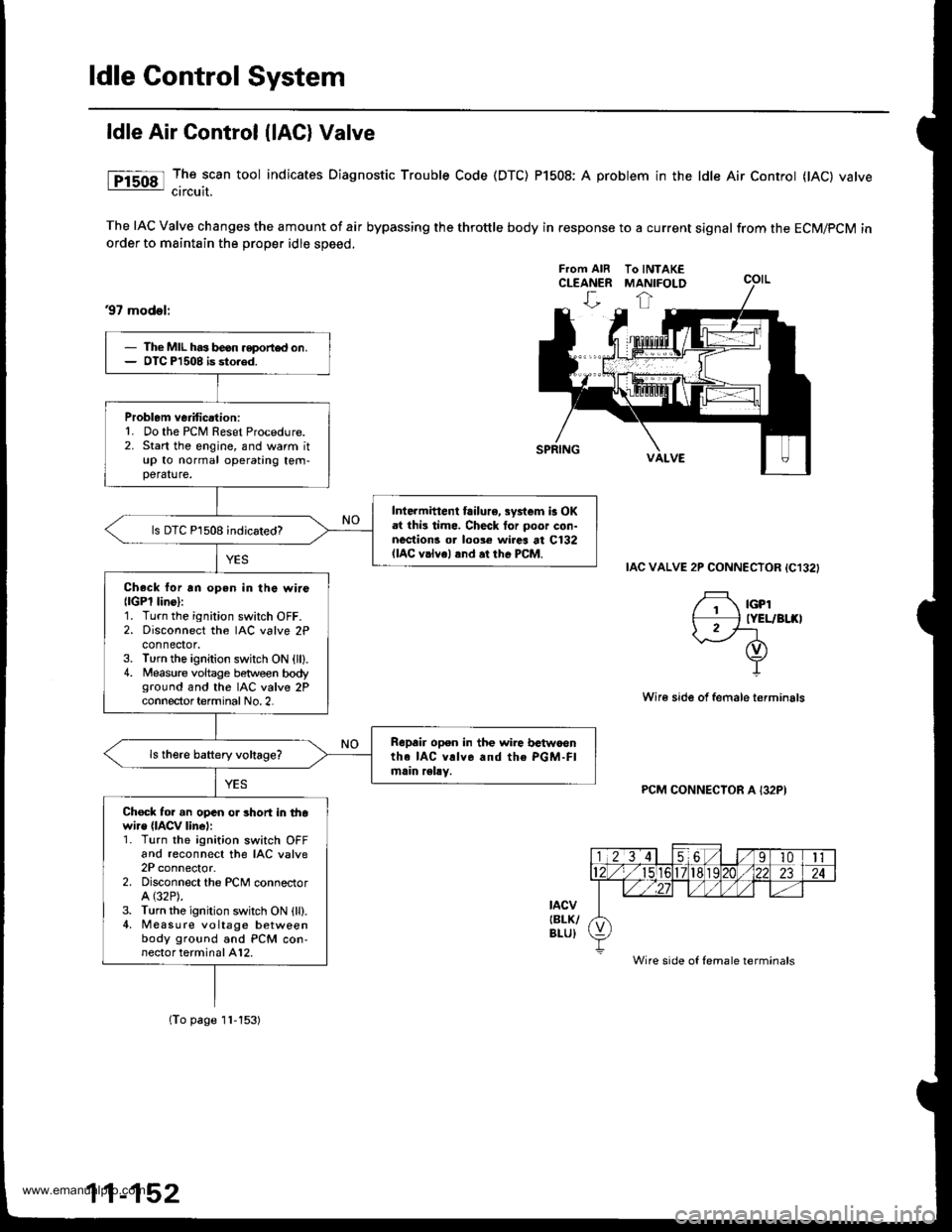
ldle Control System
ldle Air Control llAC) Valve
The scan tool indicates Diagnostic Trouble Code (DTC) Pl508: A probtem in the ldle Air Controt flAC) varvecircuit.
The IAC Valve changes the amount of air bypassing the throttle body in response to a current signal from the ECM/PCM inorder to maintain the proper idle speed.
37 model;
IAC VALVE 2P CONNECTOR {C132}
,f rcp'# IYEL/BI.(II2f-1-d)
Y
Wir€ side of female terminals
PCM CONNECTOR A I32PI
tacvIBLK/BLU)
From AIR To INTAKECLEANER MANIFOLD
Wire side of female terminals
The MIL has beon .eport€d on.OIC Pl508 is sto.ed.
Problem veiification:1. Do the PCM Reset Procedure.2. Start the engine, and warm itup to normal operating tem-perature.
Inte.mittent failure, systcm b OKat thi3 time. Check tor poo. con-nections or loose wircs at C132(lAC v.lvel and at the PCM.
ls DTC Pl508 indicated?
Check lor an open in the wir6{lGPl lins}:1. Turn the ignition switch OFF.2. Disconnect the IAC valve 2Pconnector.3. Turn the ignition switch ON {ll).4. Measure voltage between bodyground and the IAC valve 2Pconnector term inal No.2.
Repair open in the wire trctwoontha IAC v!lv6 and the PGM-Flmain relly.
Chock for an opan o. short in thowi.e (lACv linel:1. Turn the ignition switch OFFand reconnect the IAC valve2P connector.2. Disconnect the PCM conneclorA (32P).
3. Turn the ignition switch ON {ll).4, Measure voltage betweenbody ground and PCM con-nector terminal A12.
{To page 1l-153)
www.emanualpro.com
Page 356 of 1395
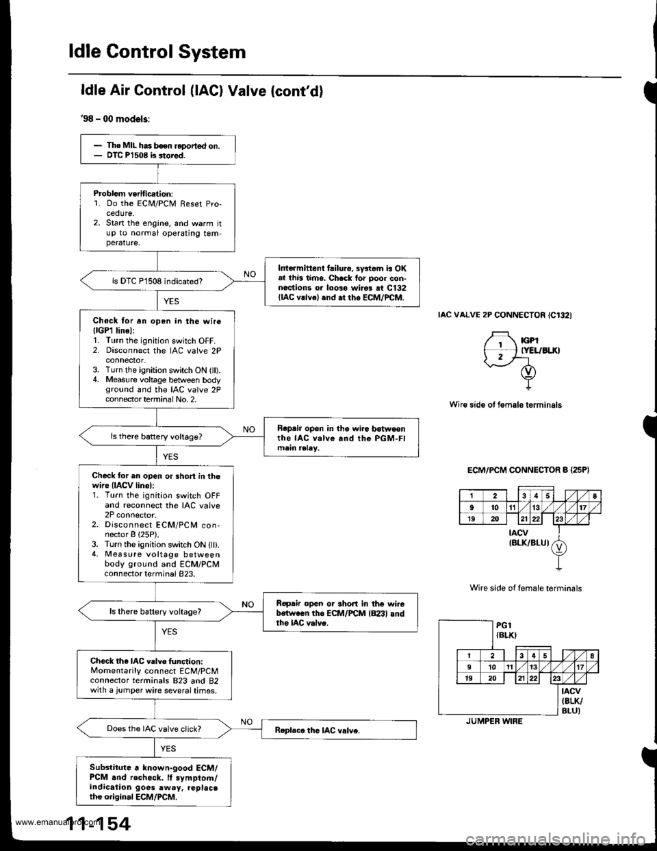
The MIL has boen r.ported on.DIC Pl 508 b 3tored.
Problem veritication:L Do the ECM/PCM Reset Pro-cedure.2. Start the engine, and warm itup to normal operating tem-perature.
Int€rmittent failure, systom is OKal lhis timo. Check lor poor con-nections or looro wirca at C132(lAc vrlvel and .t rho EcM/PcM.
ls DTC P1508 indicated?
Chock tor an open in the wir6llGPl linel:1. Turn the ignition switch OFF.2. Disconnect the IAC valve 2Pconnector,3. Turn the ignition switch ON (ll).4. Measure voltage between bodyground and the IAC valve 2Pcon nector termina I No, 2.
Repair opon in the wira botwoonthe IAC valve and tho PGM-FImain aalay.
Check tor an open or short in thewire (IACV linel:1. Turn the ignition switch OFFand reconnect the IAC valve2P connector.2. Disconnect ECM/PCM con-nector B {25P).3. Turn the ignition switch ON {ll}.4. Measure voltage betweenbody ground and ECM/PCMconnector terminal 823.
Ropair open or short in thg wirebetween tho ECM/FCM lB23l andthe IAC valve.
ls there battery voltage?
Check the IAC valve func,tion:Momentarily connect ECM/PCMconnector terminals 823 and 82with a jumper wire several times.
Does the IAC valve click?
Subslitute . known-good ECM/PCM .nd rechock. lf symptom/indication goes aw.y, replac.th€ original ECM/PCM.
ldle Air Control (lAC) Valve {cont'd}
'98 - 00 models:
IAC VALVE 2P CONNECTOR {C132I
F rcpt*l tYELrBLxlI2/'-- rf)
Y
Wire side ot fem.le terminals
ECM/PCM CONNECTOR B (25PI
Wire side of female torminals
258
9'to1l13t7
1920212223
tAcv(BLK/BLUIv
PG1{BLKI
12 | t3 4 58
910 111317
1920 | 121)22
tAcv(BLK/
BLU)JUMPER WIRE
www.emanualpro.com
Page 370 of 1395
ldle Control System
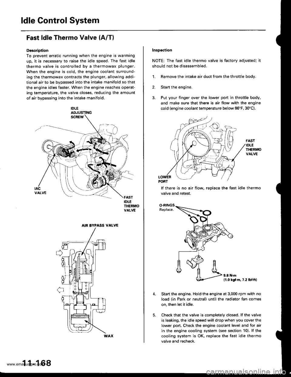
Fast ldle Thermo Valve lA/T)
Description
To prevent erratic running when the engine is warming
up, it is necessary to raise the idle speed. The fast idle
thermo valve is controlled by a thermowax plunger.
When the engine is cold, the engine coolant surround-
ing the thermowax contracts the plunger, allowing addi-
tional air to be bvDassed into the intake manifold so that
the engine idles faster. When the engine reaches operat-
ing temperature. the valve closes, reducing the amount
of air bypassing into the intake manifold.
IDLEADJUSTING
IDLETHERMOVALVE
AIR BYPASS VALVE
11-168
Inspgction
NOTE: The fast idle thermo valve is factory adjusted; it
should not be disassembled.
1. Remove the intake air duct from the throttle body.
2. Start the engine,
3. Put your finger over the lower port in throttle body,
and make sure that there is air flow with the engine
cold (engine coolant temperature below 86"F, 30'C).
lf there is no air flow, replace the fast idle thermo
valve and retest,
O-RINGSReplace.
11.0 kgfl.m, 7.2 lbl.ftl
Start the engine. Hold the engine at 3,000 rpm with no
load (in Park or neutral) until the radiator fan comes
on, then let it idle.
Check that the valve is completely closed. lf the valve
is leaking, the idle speed will drop when you cover the
lower pon. Check the engine coolant level and for air
in the engine cooling system {see section 10). lf the
cooling system is OK, replace the fast idle thermo
valve and recheck.
www.emanualpro.com
Page 384 of 1395
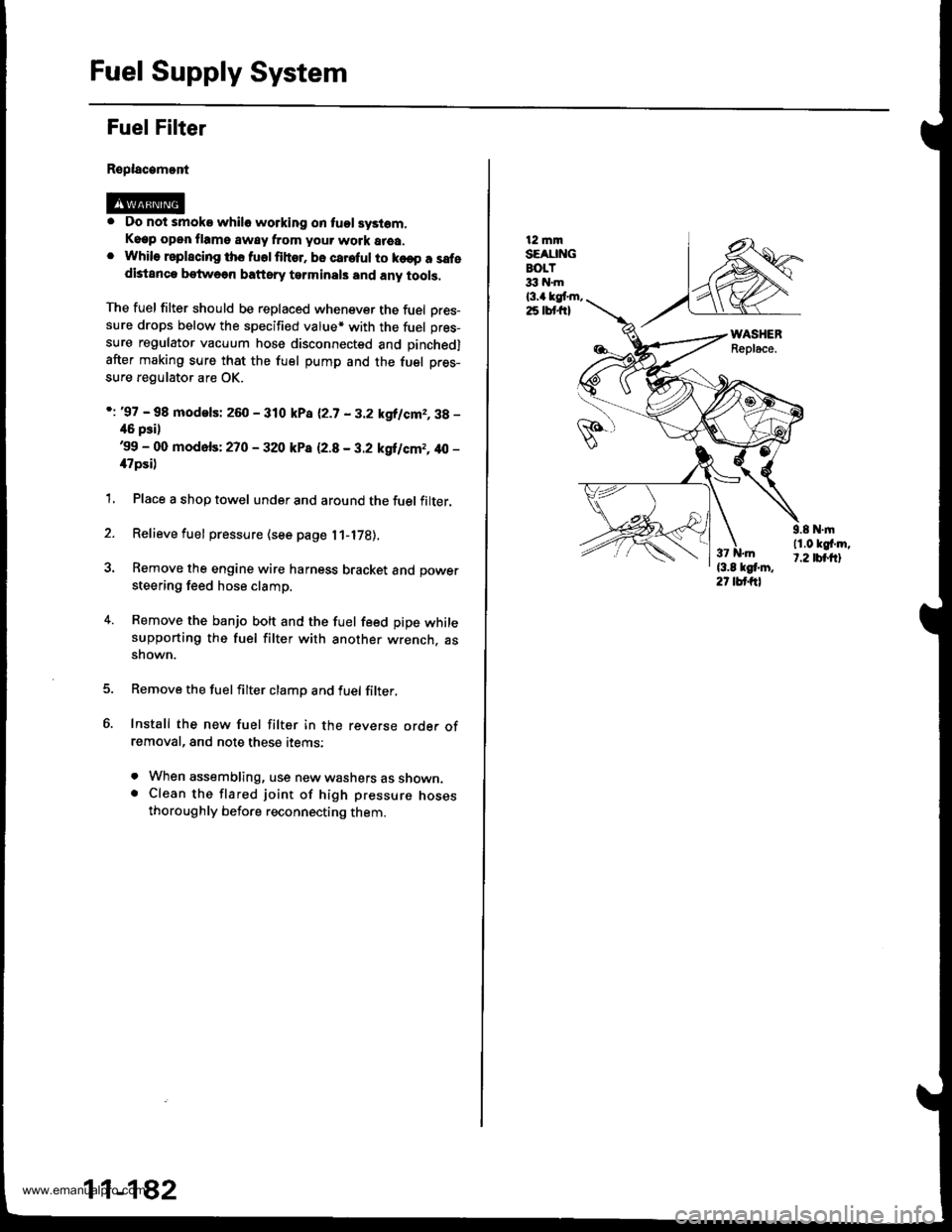
Fuel Supply System
Fuel Filter
Replacamont
. Do not smoke whilo working on tuol syslom,Keep open flame away from your work area.. While rsplscing ths fuolfihor. bo careful to ko€p a safedistanca betweon baftsry tarminals and any tools,
The fuel filter should be replaced whenever the fuel Dres-sure drops below the specified value* with the fuel pres-
sure regulator vacuum hose disconnected and pinchedl
after making sure that the fuel pump and the fuel pres-
sure regulator are OK.
i: '97 - 98 modelsi 260 - 310 kPa 12.7 - 3.2 kgllcm2,3g -
46 psil'99 - 00 mod6fs: 270 - 320 kP8 12.8 - 3.2 kgilcm2, 40 -
il7psi)
1, Place a shop towel under and around the fuel filter.
2. Relieve fuel pressure (see page l1-l7B).
3. Remove the engine wire harness bracket and power
steering feed hose clamp.
4. Remove the banjo bolt and the fuel feed pipe whilesupporting the fuel filter with another wrench. assnown.
Remove the fuelfilter clamp and fuel filter,
Install the new fuel filter in the reverse orde. ofremoval, and note these items:
. When assembling, use new washers as shown.. Clean the flared joint of high pressure nosesthoroughly before reconnecting them.
11-182
12 mmSEAUNGBOLT33 hl.m
l3.a kgt m,25 lbt frl
9.8 N.|n11.0 kgf'm,t.2 tbt.ftl
www.emanualpro.com
Page 401 of 1395
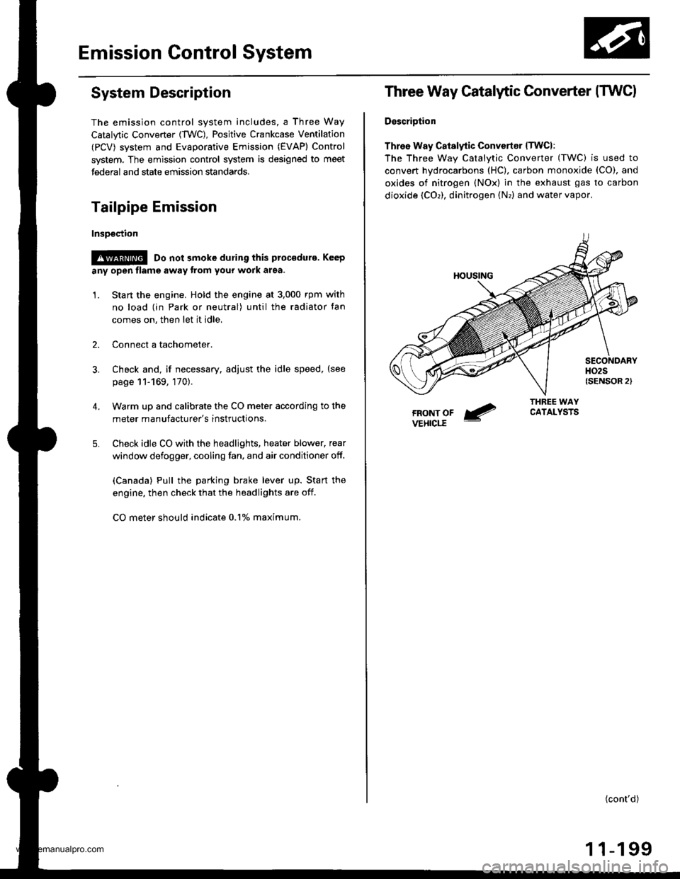
Emission Control System
System Description
The emission control system includes, a Three Way
Catalytic Converter {TWC), Positive Crankcase Ventilation
(PCV) svstem and Evaporative Emission (€VAP) Control
system. The emission control system is designed to meet
federal and state emission standards.
Tailpipe Emission
Inspsction
!@ Do not smoke during this procsdura. Keep
any open tlame away from your work area.
1. Start the engine. Hold the engine at 3,000 rpm with
no load (in Park or neutral) until the radiator fan
comes on, then let it idle,
Connect a tachometer.
Check and, if necessary, adjust the idle speed, (see
page 11-169, 170).
Warm up and calibrate the CO meter according to the
meter manufacturer's instructions.
Check idle CO with the headlights, heater blower, rear
window defogger, cooling fan, and air conditioner off.
(Canada) Pull the parking brake lever up. Start the
engine, then check that the headlights are off.
CO meter should indicate 0.1% maximum.
4.
Three Way Catalytic Converter (TWCI
DsscriDtion
Three Way Catalytic Convertsr lTwcl:
The Three wav Catalvtic Converter (TWC) is used to
convert hydrocarbons (HC), carbon monoxide (CO), and
oxides of nitrogen (NOx) in the exhaust gas to carbon
dioxide (COr), dinitrogen (Nr) and water vapor,
{cont'd)
1 1-199
www.emanualpro.com