Fault HONDA CR-V 1999 RD1-RD3 / 1.G User Guide
[x] Cancel search | Manufacturer: HONDA, Model Year: 1999, Model line: CR-V, Model: HONDA CR-V 1999 RD1-RD3 / 1.GPages: 1395, PDF Size: 35.62 MB
Page 590 of 1395
Electrical Troubleshooting ('97 Model)
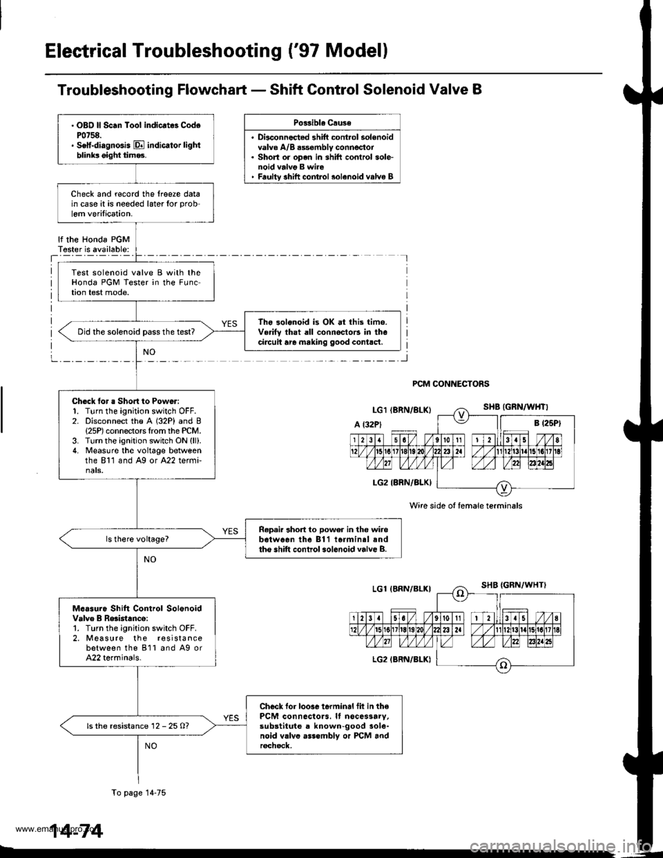
Troubleshooting Flowchart - Shift Control Solenoid Valve B
Po33ibla Crusa
. Disconnec{ed shift cont.ol solenoidvalve A/B dssombly connector. Short or open in shift conlrol sole-noid valvg B wire' Faultv shift comrol 3olenoid valvo B
lf the Honda PGMT€ster is available:
PCM CONNECTORS
Wire side ot female terminals
. OBO ll Scan Toot indicrt8 CodoP0758.. Setf-diagnGis E indicator lightblinks oight tim93.
Check and r€cord the lreere datain case it is needed later for prob
lem verilication.
Test solenoid valve B with theHonda PGM Tester in the FLrnction test mode.
The 3olonoid is OK at this time.Verifv that all connoctors in thecircuit are making good contlct.Did the solenoid Dass the test?
Chock tor a Sho.t to Power:1. Turn the ignition switch OFF.2. Disconnect the A (32P) and B{25P) connectors Irom the PCM.3. Turn the ignition switch ON (ll).
4. Measuro the voltage botveenthe 811 and Ag or A22 termi-nats.
R.p.ir 3hort to power in the wirebotwo€n the 811 iormin.l andtho shift control sol.noid valve B.
M.6sure Shift Control SolonoidValve B Reaistanco:1. Turn the ignition switch OFF.2. Measure the r€sistancebetween the 811 and A9 orA22 terminals.
Checl lor loosc terminal fil in thePCM connactors. It nocessarv,substitute a known-good aole-noid vllvo asssmbly or PCM andr6chsck,
ls the resistance 12 - 25 O?
To page 14-75
14-74
www.emanualpro.com
Page 592 of 1395
Electrical Troubleshooting ('97 Model)
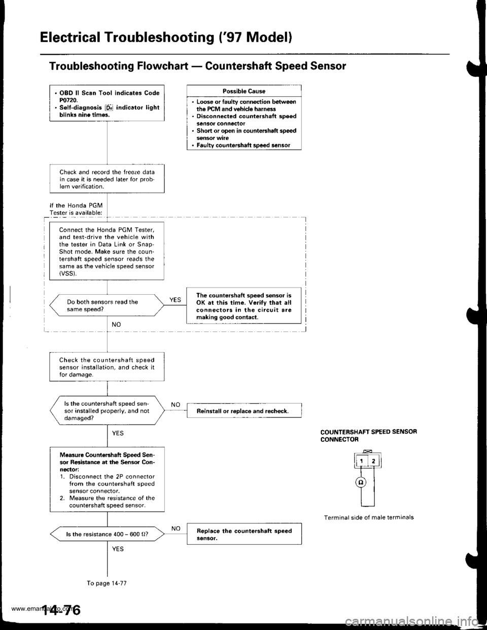
Troubleshooting Flowchart - Countershaft Speed Sensor
Possible Cause
. Loose or faulty connection betweenih€ PCM and vehicle harness. Disconnected countershaft spoedsensor conneclor. Short or open in countershaft speed
. Faulty counteBhaft speed lensor
lf the Honda PGMTester is available:I
J
COUNTERSHAFT SPEED SENSOR
CONNECTOR
ll-'T,ll-rT
ral
YIL__l
Terminal side of male terminals
. OBO ll Scan Tool indicates Codem720.' solt-diagnosis iD!' indicator lightblink3 nine tim6s.
Check and record the freeze datain case it is needed later for problem verification.
Connect the Honda PGM Tester,and test-drive the vehicle withthe tester in Data Link or snap'Shot mode, Make sure the coun-tershaft speed sensor reads thesame as the vehicle speed sensorlVSS).
The countershaft sooed sensor isOK sr this time. Veritv that allconnecloas in the circuit aremaking good contacl.
Check the countershaft speedsensor installation, and check itfor damage.
ls the countershaft speed sen-sor installed properly, and notdamaged?neinstall or roDlaco and recheck.
Measuro CountoBhaft Speed Sen-sor Relbtance at the Sensor Con-nector:1. Disconnect the 2P connectorfrom the countershaft speedsensor connector.2. Measure the resistance of thecountershaft speed sensor.
ls the resistance 400 - 600 o?
To page 14-77
14-76
www.emanualpro.com
Page 594 of 1395
Electrical Troubleshooting {'97 Model)
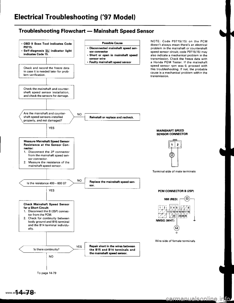
Troubleshooting Flowchart - Mainshaft Speed Sensor
Po$ible Cau3o
. Disconnocted mainshaft speod sen-sot connectot. Short or open in mainsh.ft sp6ed
' Faulty meinshaft spoed sensor
NOTE: Code P0715115) on the PCMdoesn't always mean there's an electricalproblem in the mainshaft or counlersharlspeed sensor circuit; code P0715(15) mayalso indicate a mechanical problem in thetransmission. Check the freeze data witha Honda PGM Tester. lf the mainshaftspeed sensor rpm was 0, proceed withthis troubleshooting. lf not, the probablecause is a mechanical problom within thetransmission,
MAINSHAFT SPEEOSENSOR CONNECTOR
_E_
ItiT,ll-F=r
9t
LJ
Terminal side of male terminals
PCM CONNECTOR B {25P'
Wire side of female terminals
. OBD ll Scan Tool indic.t6 Codem715.. Self-diagnosis E indic.tor lightindicatag Code 15.
Check and record the freeze datain case it is needed later {or prob,lem verification.
Check the mainshaft and counter-shaft speed sensor installation,and checkthe sensors for damage.
Are the mainshaft and counter-shaft speed sensors installedproperly, and not damaged?Reingtall or reolace and recheck.
Meaaure MaiNhatt Spoed Sen3orR6sist!nce at the Sensor Con-necaor:1. Disconnect the 2P connectorfrom the mainshaft speed sen-sor connector.2. lreasure the resistance of themainshaft speed sensor.
ls the resistance 400 - 600 O?
Check Mainahaft Speed Sensortor a Short Circuit:1. Disconnect the B (25P) connec-tor lrom the PCM.2. Check for continuity betlveenbody ground and 815 terminaland the 814 terminal individu-
ReDair short in the wir€6 b€t reenthe 815 and 814 torminals andthe mainsh!ft sp€ed sensor.
To page l4-79
14-78
www.emanualpro.com
Page 598 of 1395
Electrical Troubleshooting ('97 Model)
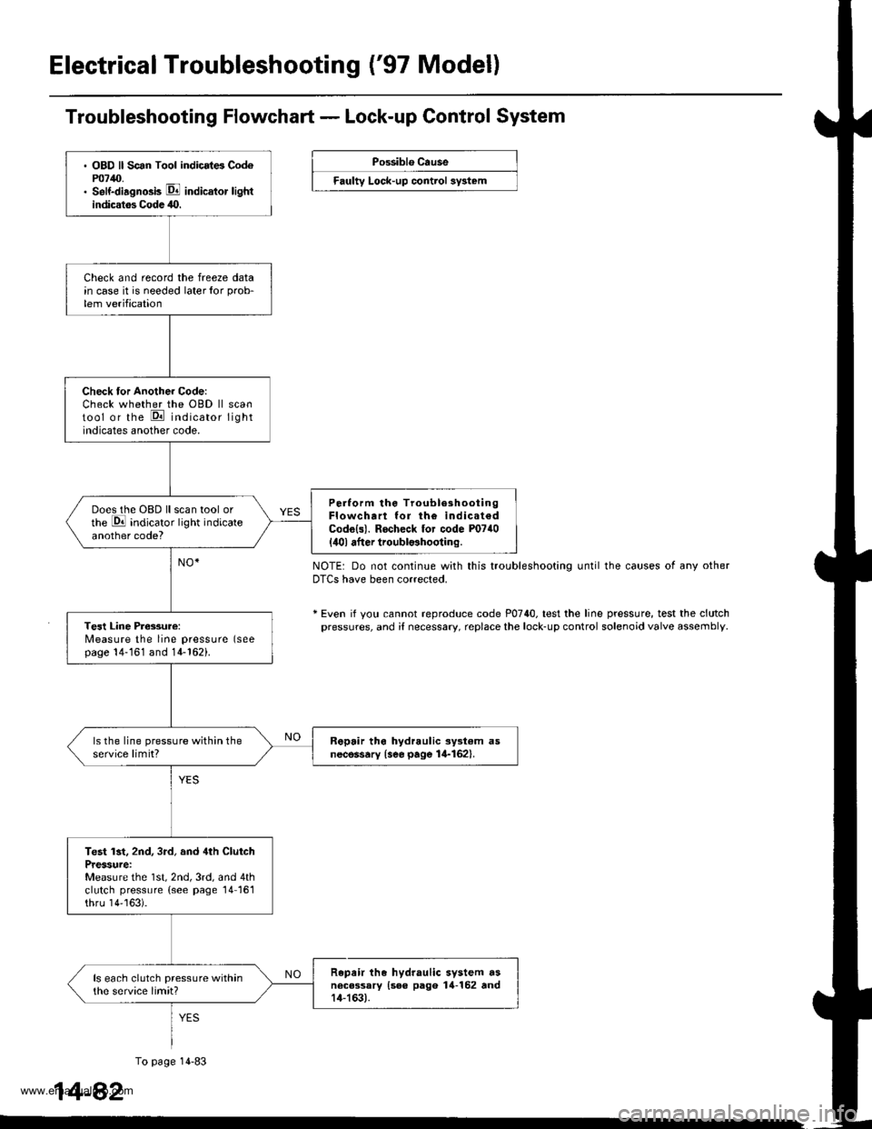
. OBD ll Scan Tool indicrt6 Cod6P0740.. Self-diagno3b E indicator lightindicatos Codc 40.
Check and record the freeze datain case it is needed laterlor prob-
lem verification
Check tor Another Code:Check whether the OBD ll scantool or the E indicator lightindicates another code.
Perlorm the TroubleshootingFlowchart lor th€ indicat€dCodo{s). Rocheck tor code P0740
{ilol after troubl$hooting.
Does the OBD ll scan tool orthe E indicator light indicateanother code?
Tesl Line Pressure:Measure the line pressure (seepage 14-161 and 14-162).
ls the line pressure within theservice limit?R6pair tho hydraulic ayst€m asnecessary {see page 14-162}.
Test lst, 2nd, 3rd, and 4th ClutchPressure:Measure the 1st, 2nd, 3rd, and 4thclutch pressure (see page 14161thru 14''163).
Repair the hydraulic system dsnecessary {see pago 14-152 rnd14-163).
ls each clutch pressure withinthe service limit?
Troubleshooting Flowchart - Lock-up Control System
Possiblo Cause
Faulty Lock-up control sy3t6m
NOTE: Do not continue with this troubleshooting until the causes of any otherDTCS have been corrected.
* Even if yotl cannot reproduce code P0740. test the line pressure, test the clutchpressures, and i{ necessary, replace the lock-up control solenoid valve assembly
1
To page 14-83
4-82
www.emanualpro.com
Page 604 of 1395
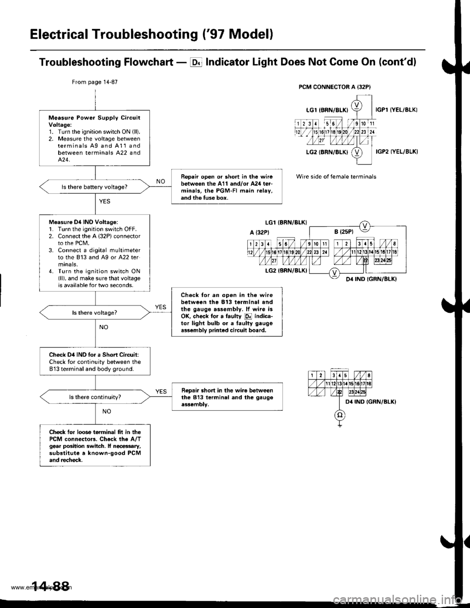
Electrical Troubleshooting ('97 Modell
Troubleshooting Flowchart - E Indicator Light Does Not Gome On (cont'dl
IYEL/BLK)
IGP2 IYEL/BLK)
Wire side of female terminals
From page 14-87
Measure Power Supply circuitVoltage:1. Turn the ignition swatch ON (ll).
2. Measure the voltage betweenterminals Ag and A11andbetween terminals A22 andA�24.
Repair open or short in the wirebotw€on the A11 and/or A24 ter-minals, the PGM-FI main relav,and ih6 fuse box.
ls there baRery voltageT
Measur€ Dil INO Voltag6:L Turn lhe ignition switch OFF.2. Connect the A 132P) connectorto the PCM.3. Connect a digital multimeterto the 813 and A9 or A22 termtnals,4. Turn the ignition switch ON(ll), and make sure that voltageis available for two seconds.
Check for an op€n in the wirebetween the 913 terminal andthe gauge assembly. lf wire isOK. check tor a faulty E indica-tor lighl bulb or a taulty gaugea$embly printed circuil bo.rd.
Check D4IND tor a Short Circuit:Check for continuity between the813 terminal and body ground.
Ropair short in the wiro betweenthe 813 lerminal and the gaugeassembly.
Check tor loose terminal frt in thePCM connector3. Chock the A/Tgear position switch. ll necessary,substitute a known-good PCMand recheck.
14-88
www.emanualpro.com
Page 607 of 1395
![HONDA CR-V 1999 RD1-RD3 / 1.G User Guide
Troubleshooting Flowchart - Interlock system - Key Interlock system
IGNITION SW]TCH 6P CONNECTOR
KEY LOCK SOL
{WHT/BLU)
ACC PUSH SW (WHT/YELI
Wire side oI female terminals
KEY LOCK SOL(WHT/BLUI
(cont HONDA CR-V 1999 RD1-RD3 / 1.G User Guide
Troubleshooting Flowchart - Interlock system - Key Interlock system
IGNITION SW]TCH 6P CONNECTOR
KEY LOCK SOL
{WHT/BLU)
ACC PUSH SW (WHT/YELI
Wire side oI female terminals
KEY LOCK SOL(WHT/BLUI
(cont](/img/13/5778/w960_5778-606.png)
Troubleshooting Flowchart - Interlock system - Key Interlock system
IGNITION SW]TCH 6P CONNECTOR
KEY LOCK SOL
{WHT/BLU)
ACC PUSH SW (WHT/YELI
Wire side oI female terminals
KEY LOCK SOL(WHT/BLUI
(cont'd)
lgnition key cannot be moved
Irom ACC (l) pGition to LOCK (0)
position while Pushing the igni-
tion kev with the shift lever in lllposifio;, and the shift lever but-
ton rcleased.
Check Key Interlock Solenoid
Op€ration:1. Disconnect the ignition switch
connector (6P).
2. Connect the No. 4 terminal of
the ignition switch 6P connec-
tor to the battery Positive ter
minal, and connect the No. 3
terminal to the battery nega
tive terminal.3. Check the key interlock sole
noid operation A clicking
so!nd sho!ld be heard.
Faulty koy interlock solenoid.
Replace the ignition key cylinder/
steedng lock as36mbly
Does the key interlock
solenoid operate properly?
Check Key Interlock Switch OPer'
adon:1. Connect the No. 5 terminal of
the ignition switch connector
to the battery Positive termi
nal, and connect the No 3 ter
minal to the baftery negative
termrnal,2. Turn the ignition switch to
ACC (l), then push rt.
3. Check the key interlock sole'
noid operation. A clicking
sound should be heard whilepushing the ignition key.
Faulty key inte.lock switch
Replaco the ignition key cylindor/
stoering lock a3r.mblY.
Does the key interlocksolenoid operate ProPerlY?
To page 14 92
14-91
www.emanualpro.com
Page 609 of 1395
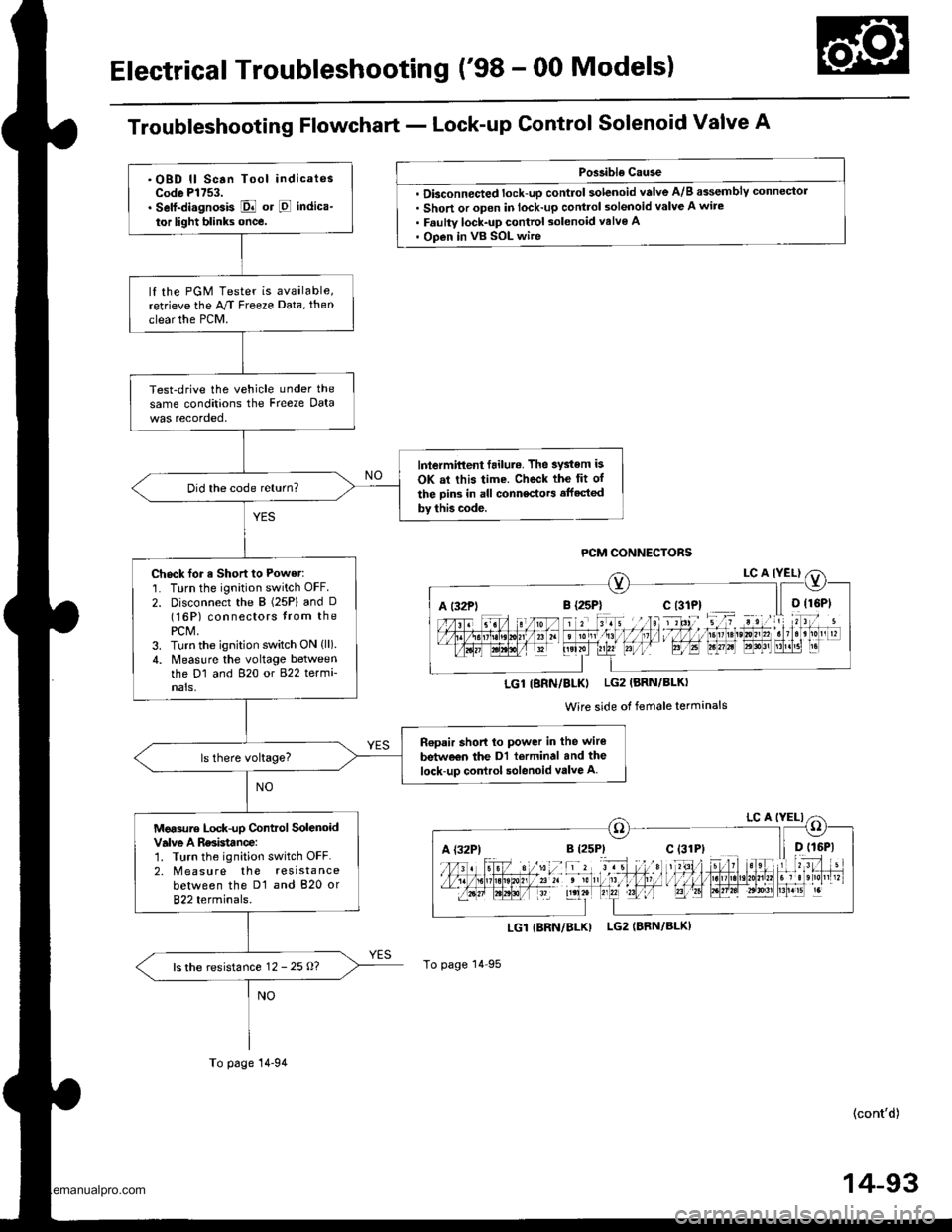
Electrical Troubleshooting ('98 - 00 Models)
Troubleshooting Flowchart - Lock-up Control Solenoid Valve A
Poslible Cause
. Dbconnected lock-up control solenoid valve A/B assemblY connector. Short or open in lock-up control solenoid valve A wire. Faulty lock-up control solenoid valve A' Open in vB SOL wire
LGI|BRN/BLK) LG2IBRN/BLK)
To page 14 95
(cont'd)
14-93
A t32Pli r rriltI l,1 I I ltDrste,0n,,2. t3r B'r!51 r.
LGl IBRN/BLKI LG2 (BRN/BLKI
Wire side of female terminals
A {32P)
.OBD ll Scan Tool indicatesCode Pl753.. Self-di.gnosis E or E indica-
tor light blinks once.
lf the PGM Tester is available,retrieve the M Freeze Data, then
clear the PCM.
Test-drive the vehicle under the
same conditions the Freeze Data
lntermittent failul.. The system is
OK at this time. Check the fit of
the Din3 in all connectors affected
by thb code.
Did the code return?
Check for a Short to Power:'1. Turn the ignition switch OFF.
2. Disconnect the B (25P) and D(16P) connectors trom thePCM,3. Turn the ignition switch ON (ll).
4. Measlre the voltage betweenthe D1 and 820 or 822 termi-nals,
n€pair short lo power in the wire
betw€€n the Dl terminal and the
lock-up control solenoid valve A
Mg.sure Lock-up Control SolenoidValve A Rssistance:1. Turn the ignition switch OFF.2. M easu re the resistancebetween the D1 and 820 or822 terminals.
ls the resistance 12 - 25 o?
To page 14-94
www.emanualpro.com
Page 615 of 1395
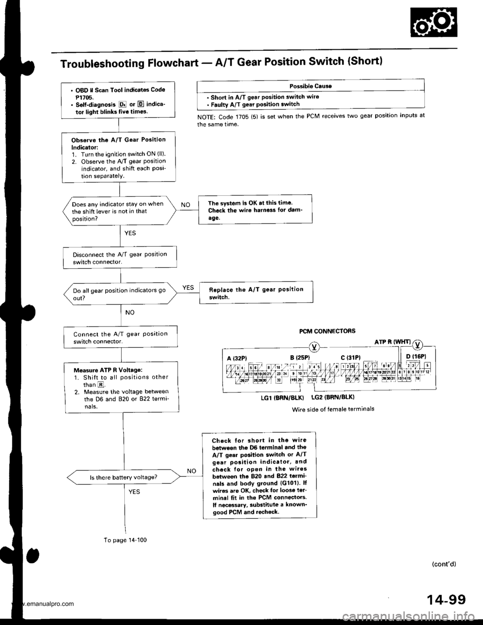
TroubleshootingFfowchart - AIT Gear Position Switch {Short)
Possible Cau3e
. short in A/T gear position switch wire. Faulty A/T gear pGition switch
NOTE: Code 1705 (5) is set when the PCM receives two gear position inputs at
the same time,
PCM CONNECTORS
A (32P1
LGl IBRN/BLK) LG2 (BRN/BLK)
Wire side of female terminals
' O8O ll Scan Tool indicatas Code
P1705.. self-diagnGi3 E or El indica'
tor light blinks five time3
Obs€rve the A/T Goar Position
lndicalor:1. Turn the ignition switch ON (ll).
2. Observe the A/T gear Positionindicator, and shift each Posi'tion seParatelY.
The system is OK at lhis time.
Check the wir€ harne3s fot dam'
age.
Does any indicator stay on when
the shift lever is not in thatposition?
Moasu.e ATP R Voltage:1. Shift to all positions other
than E.2. Measure the voltage between
the D6 and 820 or 822 termi-nals,
Check for short in the wire
betwoon thc DS terminal and tho
A/T gear position switch or A/Tgear porition indicatol, and
check for open in the wires
batween the 820 and 822 t6lmi'
nals and body ground 1G1011. lf
wires are OK, check lor loos€ i€r_
minel fit in the PCM connectors.
lf necBsarv, substittlle a known'good PCM and recheck.
To page'14-100
(cont'd)
14-99
www.emanualpro.com
Page 619 of 1395
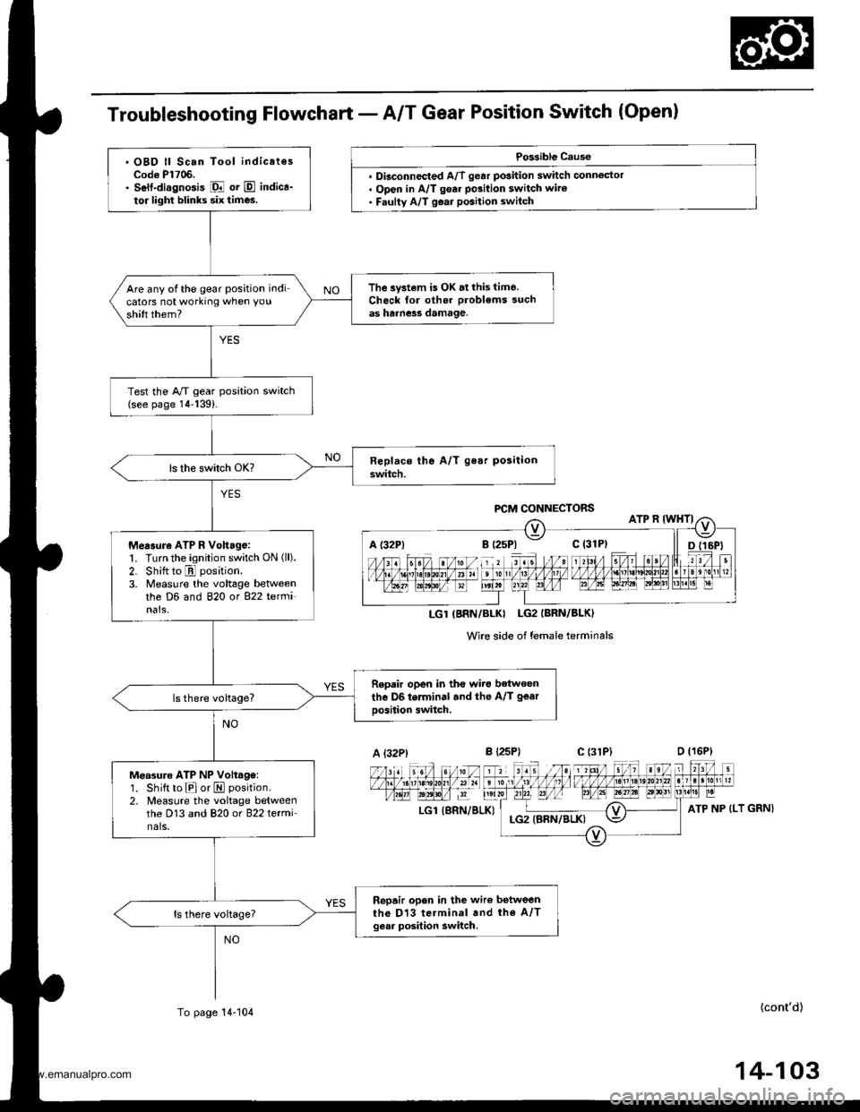
Troubleshooting Flowchart - A/T Gear Position Switch (Open)
Po$iblg Cause
. Dbconnected A/T gear position switch connoctor. Open in A/T gear po3ition switch wiro. Faulty A/T g€ar position switch
Wire side of female terminals
LGl {SRN/BLK)
{cont'd)
P,CM CONNECTORS
LGT(BNN/BLKI LG2IBRN/BLK)
A {32P)c l31P)
ATP NP (LT GRN}
. OBD ll Scan Tool indicatesCodo Pl706.. Self-diagnosis Fl or E indica-to. lighl blinks six times.
The system is OK.tthis time.Check for oth6r probl€ms suchas harne3s damage.
Are any ofthe gear position indicators not working when you
shift them?
Test the A/T gear position switch(see page 14-139).
Measure ATP R Vohago:1. Turn the ignition switch ON (ll).
2. Shitt to E position.
3. Measure ihe voltage betweenthe D6 and 820 ot 822 tetfiinals,
Repair open in tho wiro betwoenthe D6 terminal and the A/T gear
oosition switch.
Measure ATP NP Volt.g€:1. Shift to Elor E position.
2. Measure the voltage betweenthe D13 and 820 or 822 terminals,
Repair open in the wiro betweenth€ Dl3 terminal and th€ A/Tgesr posilion awitch.
To page 14-104
14-103
www.emanualpro.com
Page 622 of 1395
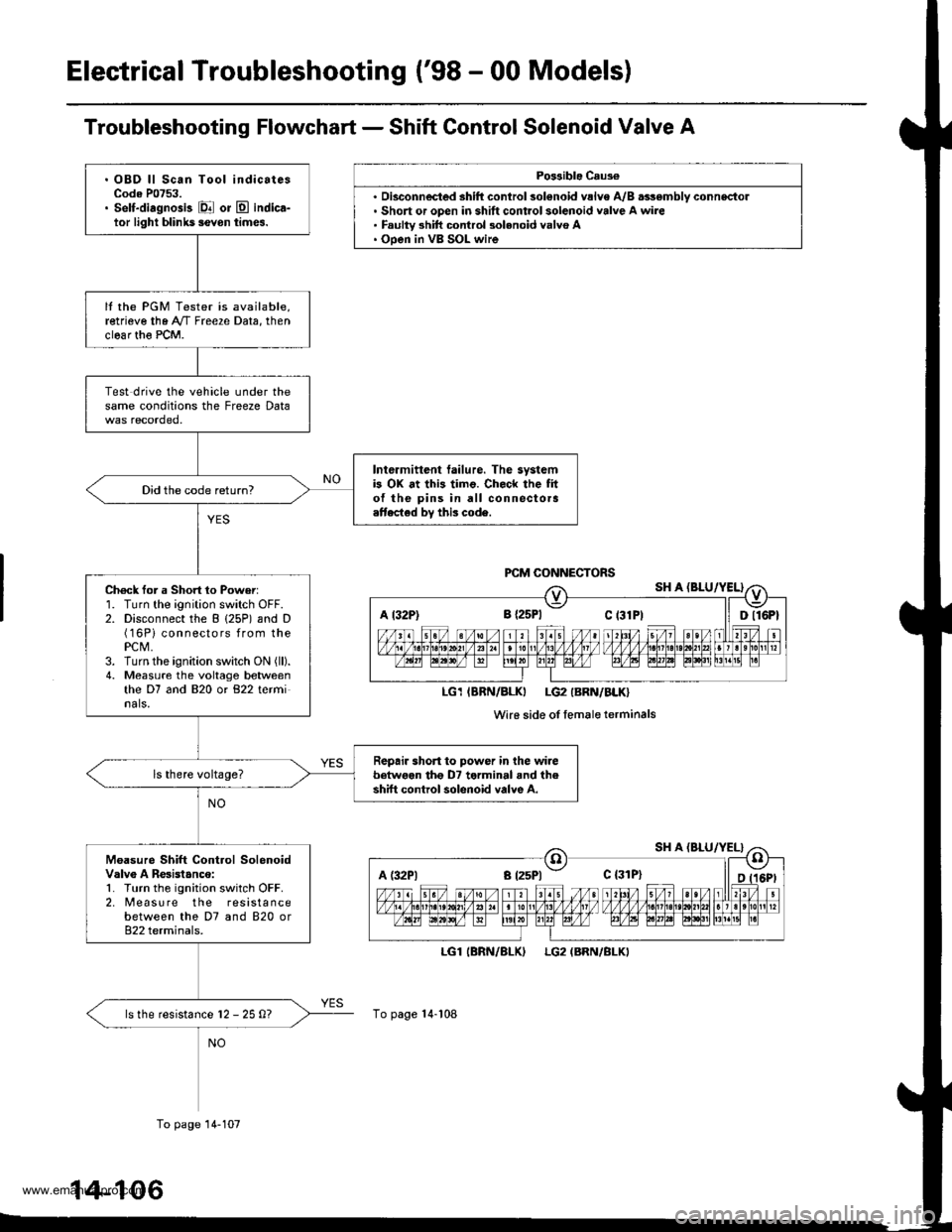
Electrical Troubleshooting ('98 - 00 Models)
Troubleshooting Flowchart - Shift Control Solenoid Valve A
Po$ible Caus€
'. Short or open in shift control solenoid valve A wire. Faulty 3hift control 3olenoid valvo A. Ooen in VB SOL wire
LGl
To page 14-108
(BRN/BLKILG2 (BRN/BLKI
A t32P) 8 {2sPl Ct3lPt ll Dll6Pt
LG1IBRN/BLKI LG2IBRN/BLK}
Wi16 side of femaleterminals
A (:l2Pl a t25Pl - c {31P}
. OBD ll Scan Tool indicatesCode P0753.. Self-diagnosis El or E indica-tor light blihk5 ievon times.
It the PGM Tester is available,retrieve the A"/T Freeze Data, thenclear th€ PCM.
Test drive the vehicle under thesame conditions the Freeze Data
Intermittent tailure. The systemb OX at this timo. Check the fito{ the pins in all connectora.ttected by this code.
Did the code return?
Ch6ck for a Short 1o Power:1. Turn the ignition switch OFF.2. Disconnect the B (25P) and D(16Pi connectors from thePCM,3. Turn the ignition switch ON (ll).
4. Measure the voltage betweenthe D7 and 820 or 822 terminals.
Repair short to power in the wirebetwoen tho D7 terminal and theshift control solenoid valve A.
Moasure Shift Control SolenoidValv6 A Resistanco:1. Turn the ignition switch OFF.2. [reasu re the resistancebetween the D7 and 820 or822 terminals.
ls the resistance l2 - 25 0?
To page 14-107
14-106
www.emanualpro.com