Gear position switch HONDA CR-V 1999 RD1-RD3 / 1.G Owner's Manual
[x] Cancel search | Manufacturer: HONDA, Model Year: 1999, Model line: CR-V, Model: HONDA CR-V 1999 RD1-RD3 / 1.GPages: 1395, PDF Size: 35.62 MB
Page 578 of 1395
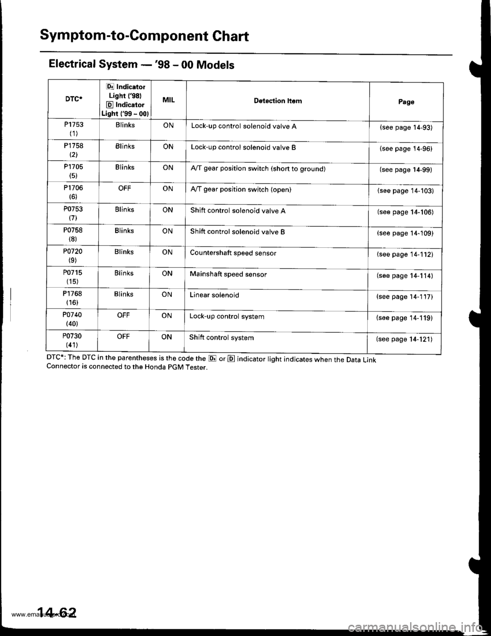
Symptom-to-Component Chart
Electrical System -'98 - 00 Models
DTC*; The DTC in the parentheses is the code the E or E indicator light indicates when the Data LinkConnector is connected to the Honda pGM Tester.
DTC*
Et Indicatol
Lighr (98)
E Indicator
Light ('99 - 00)
MILDetestion ltomPage
P1753
(1)BlinksONLock-up control solenoid valve A{see page 14-93)
P1758
(21BlinksONLock-up control solenoid valve B(see page 14-96)
P1705(5)BlinksONA,/T gear position switch (shon to grounol(see page 14-99)
P1706(6)OFFONA,/T gear position switch (open)(see page 14-103)
P0753
(71Blin ksONShift control solenoid valve A(see page 14-106)
P0758
(8)BlinksONShift control solenoid valve B(see page 14-109)
P0720
(9)BlinksONCountershaft speed sensor{see page 14-112)
P0715
{15)
BlinksONMainshaft speed sensor(see page 14-114)
P1768
(16)BlinksONLinear solenoid(see page 14-117)
POl 40(40)OFFONLock-up control system(see page 14-119)
P0730
(41)OFFONShift control system(see page 14-121)
14-62
www.emanualpro.com
Page 584 of 1395
Electrical Troubleshooting {'97 Model}
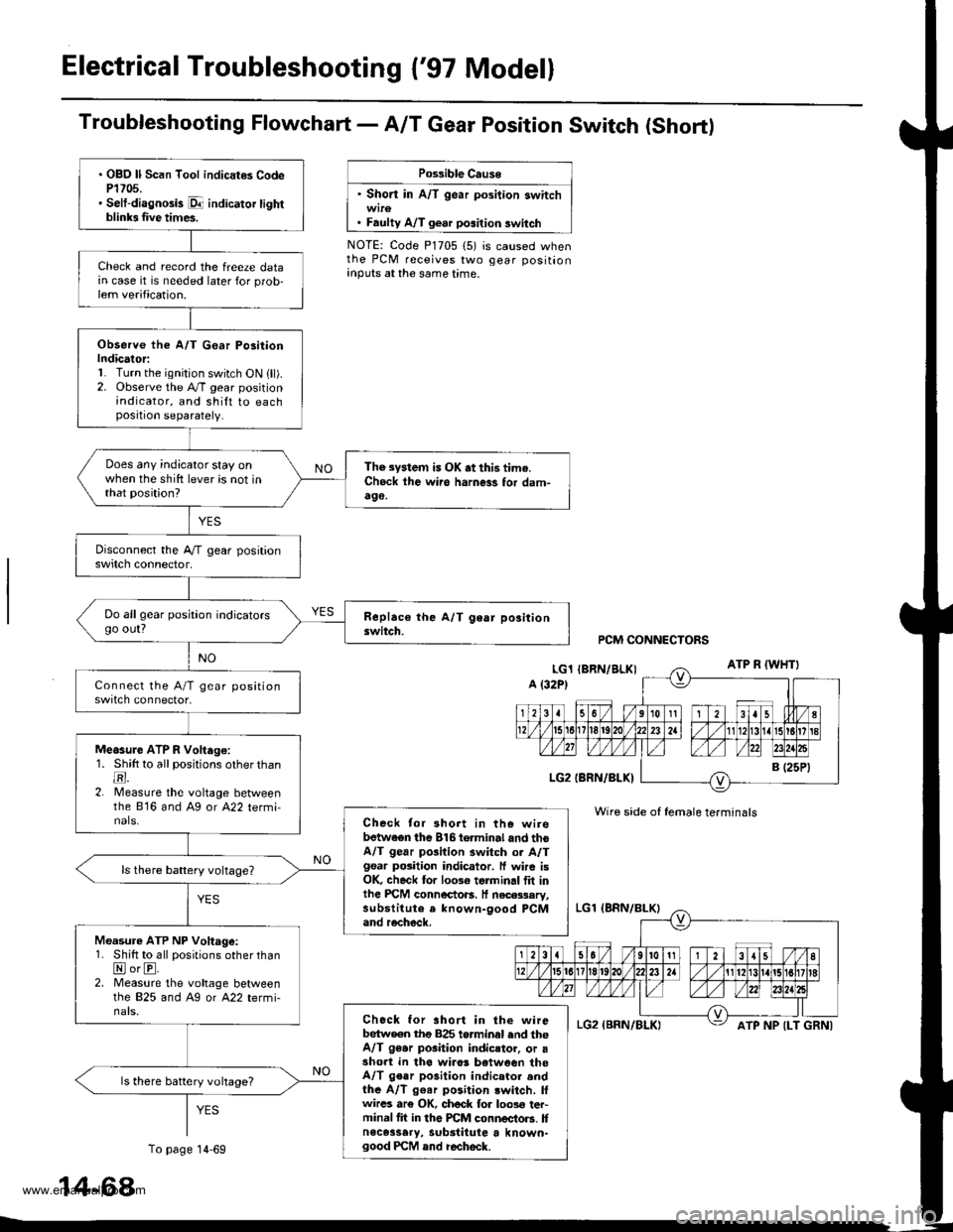
Troubfeshooting Flowchart- AIT Gear Position Switch (Short)
Po$ible Cause
' Short in A/T gear position switch
. Faulty A/T gear position switch
NOTE: Code P1705 (5) is caused whenthe PCM receives two gear positionanputs at the same time.
. OBO ll Scan Tool indicat€s CodeP1705.' Selt-diagnosis p1- indicator tightblinb Iive times.
Check and record the freeze datain case it is needed later for prob-lem verification.
Observe the A/T G€ar Po3itionIndicator:1. Turn the ignition switch ON lll).2. Observe the A./T gear positionindicator, and shilt to eachposition separately.
Does any indicator stay onwhen the shift lever is not inthat position?
The system is OK .t this time.Ch6ck ihe wii6 harness for dam-490,
Do allgear position indicatorsgo out?
Measure ATP R Voltago:1. Shitt to all positions other thantr.2. lMeasure the voltage betweenthe 816 and Ag or A22 termi-nals.Check tor 3hort in the wirebetwaen the 816torminal and thoA/T gear pGilion switch or A/Tgsar posiiion indicator. ff wire isOK, check for 10036 torminal flt inlhe PICM connectoB. It necessary,substitute a known-9ood PCMand recheck.
Measure ATP NP Voltage:1. Shift to all positions other thanNorE.2. Measure the vohage betweenlhe 825 and Ag or A22 termi-nals.Chock for ahort in the wirebetw€en tho 825 torminal end theA/T 96.r pGition indicstor, or asho.t in tha wiro! b€tween theA/T gear po3ition indicator andthe A/T g€ar position lwitch. lfwircs ar€ OK, ch6ck for loos€ ter-minal fit in the PCM connectors. Itnece3sary, substitute a known-good PCM and recheck.
ls there battery vohage?
PCM CONNECTORS
Wire side of female terminals
ATP NP {LT GRNI
14-68
To page 14-69
www.emanualpro.com
Page 585 of 1395
From page 14-68
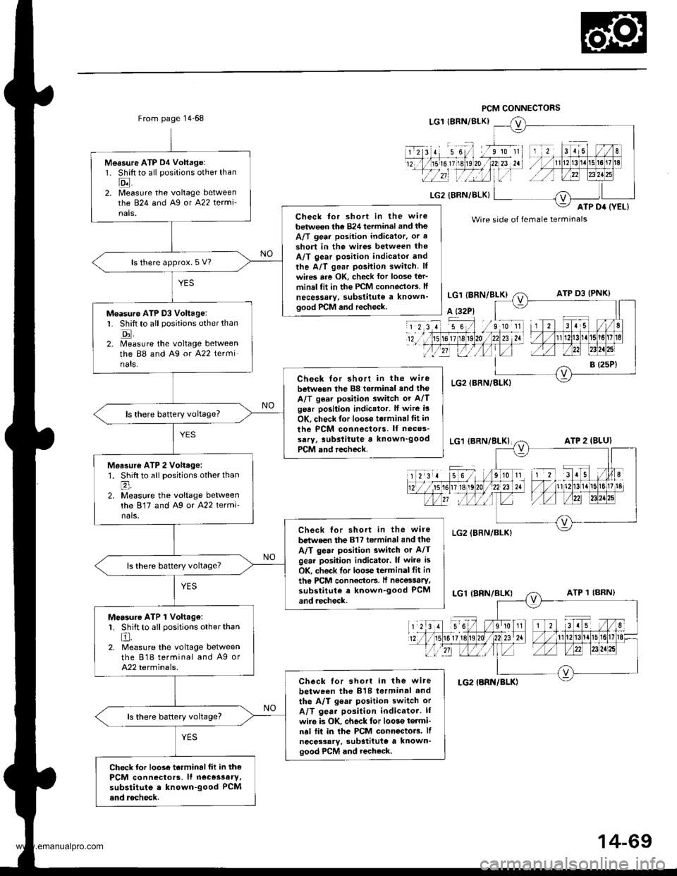
Measure ATP D4 Voltage:1. Shift to all positions other than
Eil2. [/leasure the voltage betweenthe 824 and Ag or A22 termi-nals.Check tor short in the wire
between the 824 terminal and theA/T geai position indicator. or a
3hort in the wir6s between theA/T gear position indicttor and
the A/T gear position switch. lf
wires are OK, check lor loose ter'minal fit in the PCM conneclo.s. lf
necessary, substitute a known'good PrCM and recheck.
ls there approx. 5 V?
M€asure ATP D3 Voltage:L Shift to all positions other than
tr.2. Measure the voltage betweenthe 88 and A9 or A22 terminats.
Check for short in the wi.ebetween the 88 torminal and the
A/T gear position switch or A/Tgear position indicator. lf wire i3
OK, check lor loose terminaltit in
the PCM connectors. lf neces-
sarY, 3ubslitute a known'goodPCM and recheck.
ls there baftery voltage?
Measur€ ATP 2 Vohage:1. Shift to all positions other thanl;
2. Measure the voltage betweenthe 817 and Ag or A22 termi'nals.
Check for short in the wire
bstwe€n the 817 terminal and the
A/T gear posilion switch or A/Tgear position indicator. lf wire is
OK, check lor loose terminal fit in
th6 PCM conn€ctoF. lf nec€ssaty,substitute a known-good PCMand recheck.
Mersure ATP 1 Volt.ge:1. Shift to all positions other than
El.2. Measure the voltage betweenthe 818 terminal and A9 orA22 terminals.
Check lor short in the wire
betw.en the 818 torminal and
the A/T gear position switch or
A/T gear position indicator. lI
wiro is OK. check for loose termi-nal fii in the PCM connectorc. lf
necessary. substitute a known'good PCM and recheck.
ls there battery voltage?
Check for loose terminalfit in thePCM connectors, lf neces3aty,substitute e known-good PCMend rocheck.
Wire side of female terminals
14-69
www.emanualpro.com
Page 586 of 1395
Electrical Troubleshooting ('97 Model)
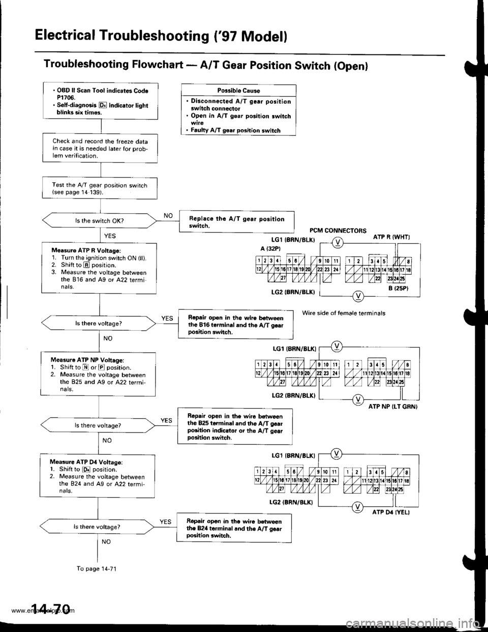
Troubleshooting Flowchart - A/T Gear position Switch (Openl
Po$iblo C.u3e
. Disconnected A/T gear positionswitch connectol. Open in A/T goar position switch
. Faulty A/T goar position switch
Wire side ot temale terminals
ATP NP ILT GRNI
. OBD ll Scan Tool indicat6 CodeP1706.. Setf-diagnGb Dl indicator tightblinks six tim$.
Check and record the freeze datain case it is needed later for prob-lem verilication.
Test the A,/T gear position switch{see page 14139).
Measu.e ATP R Voltage:'1. Turn the ignition switch ON (ll).2. Shift to E position.3. Measure the voltage betweenthe 816 and Ag or A22 termi-nals.
Repeir op€n in the wire botweenthe 816t€rminaland the A/T g€.rpo3ition switch.
Measure ATP NP Voltage:1. Shift to E or E position.2. Measure the voltage betweenthe 825 and A9 or A22 termi-na ls,
Repai. open in th6 wir6 bctwoanthe 825 terminal and tho A/T gearpolition indicltor or tho A/T gea.Doshion swhch.
Moasure ATP 04 Voltage:1. Shift to E position.2. Measure the voltage betweenthe 824 and A9 or A22 termi-nars,
Ropai. opcn in tho wiro betwoenthe B24 torminal .nd the A/T gcarDosition switch.
To page 14-71
14-70
www.emanualpro.com
Page 587 of 1395
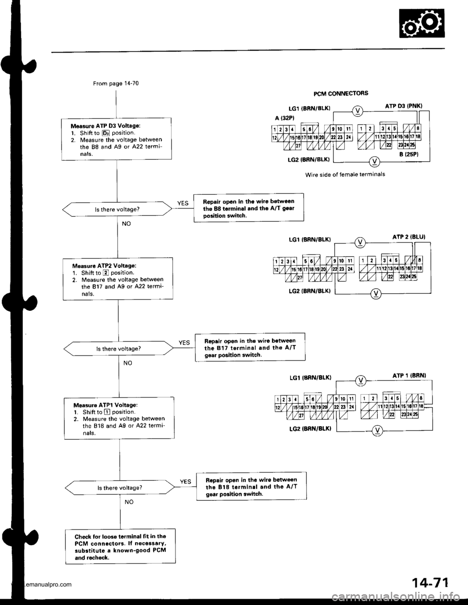
From page 14-70
Measure ATP D3 Vohag€:1. Shift to E position.
2. Nleasure the voltage betweenthe 88 and Ag or A22 terminals,
Repair open in the wirg bstween
the 88 tolminal and tho A/l gear
oo3ition 3witch.
Msasure ATP2 Volttg6:'1. Shiftto E position.
2. Measure the voltage between
the 817 and A9 or A22 termi'nals.
Repair open in lhe wire between
the 817 terminal and tho A/Tgear position switch.
Moasure ATP1 Voltage:1. Shift to A position.
2. Measure the voltage betweenthe 818 and Ag or A22 termi-nats,
R€pair opon in the wiro betweenthe 818 terminll and the A/Tgoar poshion switch.
Check tor looso terminal fit in thePCM connectors. lf necossarY,substitute a known-good PCM
and rechock.
FCM CONNECTORS
Wire side of female terminals
www.emanualpro.com
Page 602 of 1395
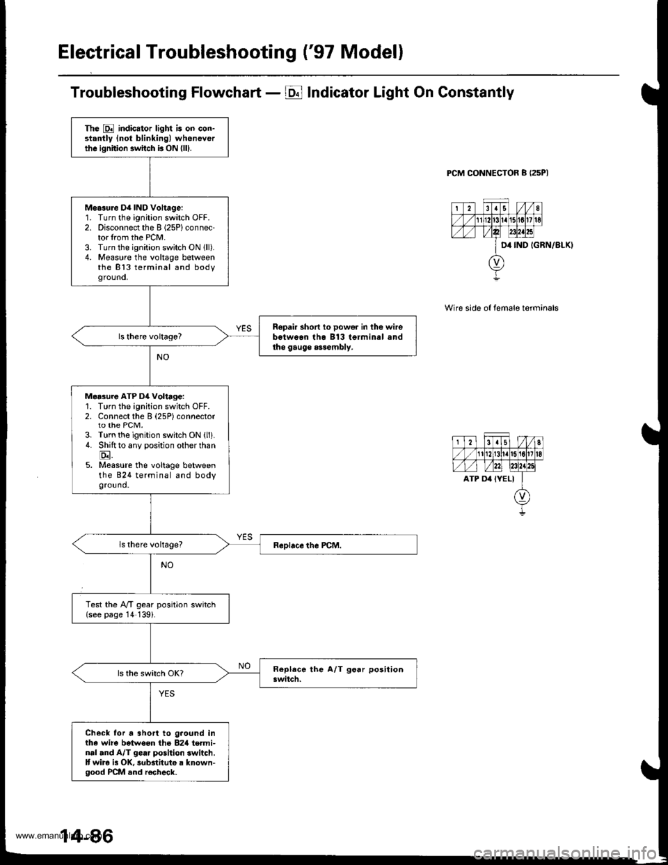
Electrical Troubleshooting ('97 Modell
Troubleshooting Flowchart - E Indicator Light On Constantly
PCM CONNECTOR B I25PI
IGRN/8LKI
Wire side of temale terminals
The E indicator light is on con-stantly {not blinking) wheneverthe ignition switch b ON (lll.
Measure D4 IND Voltage:'1.
2.
3.4.
Turn the ignition switch OFF.Disconnect the I (25P) connec-tor lrom the PCM.Turn the ignition switch ON lll).Measure the voltage betweenthe 813 terminal and bodygrouno,
Ropair short to powor in the wirebetwean tho B13 terminal andtho gauge assembly.
Maa3ure ATP D4 Voltage:1. Turn the ignition switch OFF.2. Connect the B (25P) connectorto the PCM.3. Turn the ignition switch ON (ll).
4. Shiftto any position other than
E.5. Measure the voltage betweenthe 824 terminal and bodyground.
Test the lVT gear position switch(see page '14 139).
Check lor a short to g.ound inthe wire betwoen tho B2rl te.minal and A/T gear position switch.It wira i3 OK, substitute a known-good PCM and r€check.
www.emanualpro.com
Page 604 of 1395
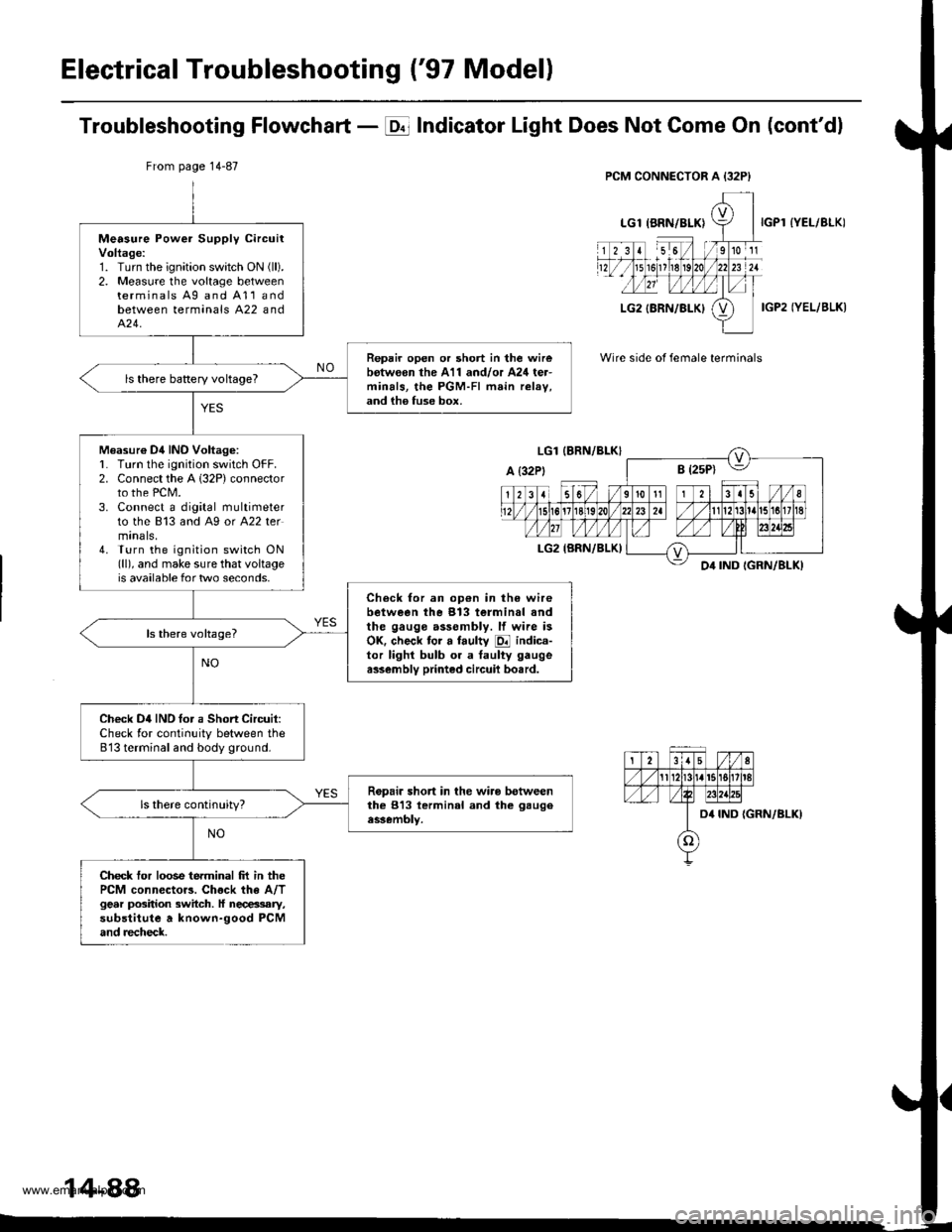
Electrical Troubleshooting ('97 Modell
Troubleshooting Flowchart - E Indicator Light Does Not Gome On (cont'dl
IYEL/BLK)
IGP2 IYEL/BLK)
Wire side of female terminals
From page 14-87
Measure Power Supply circuitVoltage:1. Turn the ignition swatch ON (ll).
2. Measure the voltage betweenterminals Ag and A11andbetween terminals A22 andA�24.
Repair open or short in the wirebotw€on the A11 and/or A24 ter-minals, the PGM-FI main relav,and ih6 fuse box.
ls there baRery voltageT
Measur€ Dil INO Voltag6:L Turn lhe ignition switch OFF.2. Connect the A 132P) connectorto the PCM.3. Connect a digital multimeterto the 813 and A9 or A22 termtnals,4. Turn the ignition switch ON(ll), and make sure that voltageis available for two seconds.
Check for an op€n in the wirebetween the 913 terminal andthe gauge assembly. lf wire isOK. check tor a faulty E indica-tor lighl bulb or a taulty gaugea$embly printed circuil bo.rd.
Check D4IND tor a Short Circuit:Check for continuity between the813 terminal and body ground.
Ropair short in the wiro betweenthe 813 lerminal and the gaugeassembly.
Check tor loose terminal frt in thePCM connector3. Chock the A/Tgear position switch. ll necessary,substitute a known-good PCMand recheck.
14-88
www.emanualpro.com
Page 615 of 1395
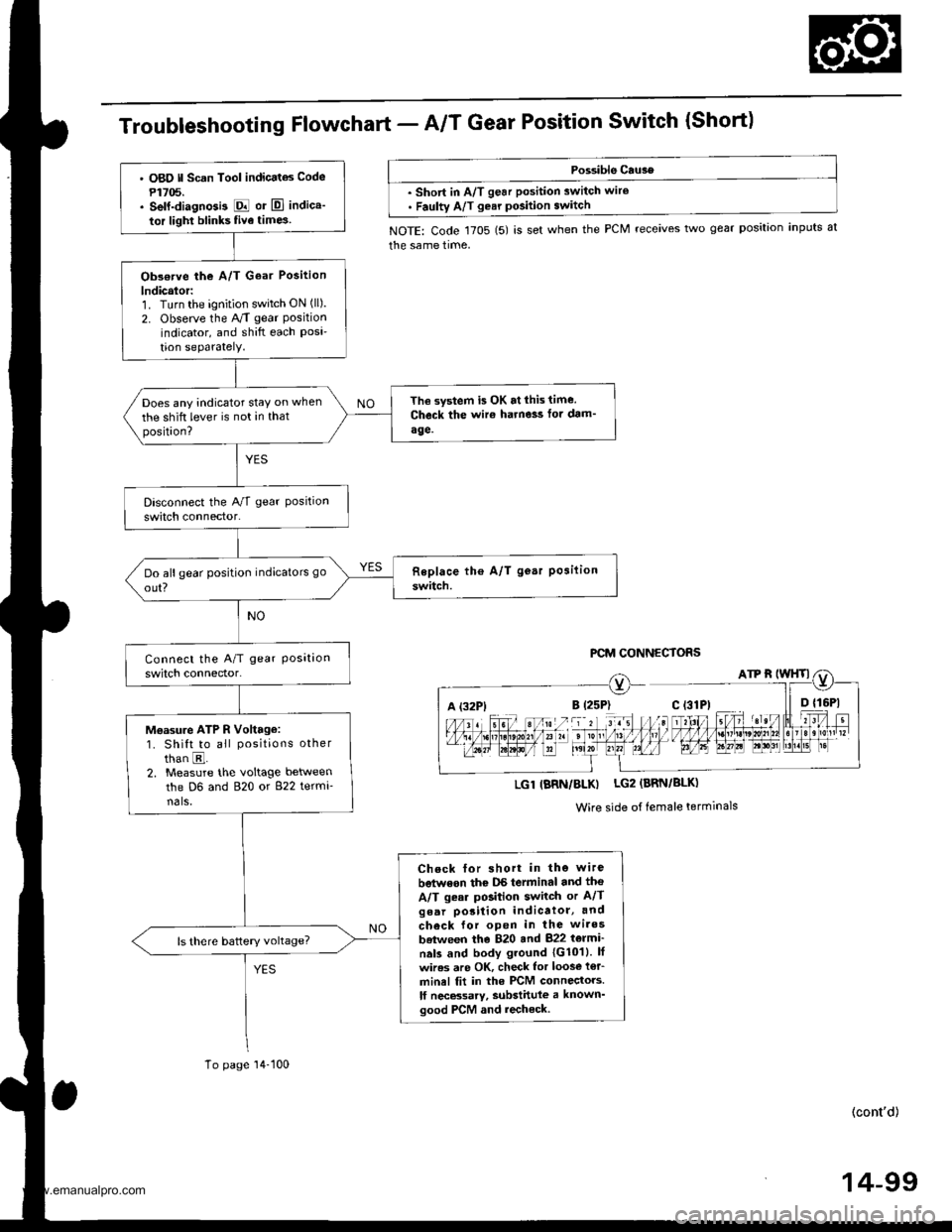
TroubleshootingFfowchart - AIT Gear Position Switch {Short)
Possible Cau3e
. short in A/T gear position switch wire. Faulty A/T gear pGition switch
NOTE: Code 1705 (5) is set when the PCM receives two gear position inputs at
the same time,
PCM CONNECTORS
A (32P1
LGl IBRN/BLK) LG2 (BRN/BLK)
Wire side of female terminals
' O8O ll Scan Tool indicatas Code
P1705.. self-diagnGi3 E or El indica'
tor light blinks five time3
Obs€rve the A/T Goar Position
lndicalor:1. Turn the ignition switch ON (ll).
2. Observe the A/T gear Positionindicator, and shift each Posi'tion seParatelY.
The system is OK at lhis time.
Check the wir€ harne3s fot dam'
age.
Does any indicator stay on when
the shift lever is not in thatposition?
Moasu.e ATP R Voltage:1. Shift to all positions other
than E.2. Measure the voltage between
the D6 and 820 or 822 termi-nals,
Check for short in the wire
betwoon thc DS terminal and tho
A/T gear position switch or A/Tgear porition indicatol, and
check for open in the wires
batween the 820 and 822 t6lmi'
nals and body ground 1G1011. lf
wires are OK, check lor loos€ i€r_
minel fit in the PCM connectors.
lf necBsarv, substittlle a known'good PCM and recheck.
To page'14-100
(cont'd)
14-99
www.emanualpro.com
Page 616 of 1395
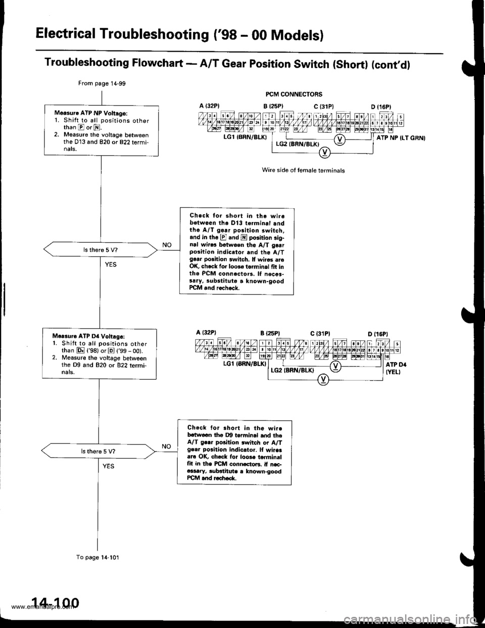
Electrical Troubleshooting ('98 - 00 Modelsl
Troubleshooting Flowchart - A/T Gear position switch (short) (cont'dl
FCM CONNECTORS
B t25Plc (31P)
Wire side of lemale terminals
A t32Pl
LGl {BRN/BLK)
From page 1 4-99
To page 14-101
Measur. ATP NP Voltago:1. Shift to all positions otherthan E or E.2. Measure the voltage belweenthe 013 and 820 or 822 termi-nats.
Check for short in the wir6b.twoen tha Dl3 terminal andthe A/T go.r polition 3witch,and in th6 El and E poiition sig-nal wir.! betwoen the A/T garrpo3ition indicetor and the A/Tgarr position switch. lf wi.6s areOK, check for loole torminal fit intho PCM connccto.s, lf necca-sary, lubstituto a known-goodPCM and rocheck.
Mcrsure ATP D4 Vohrg6:1. Shift to all positions otherthan E {'98) or El ('99 - oo).2. Measure the voltage betweenthe Dg and 820 or 822 termi-nals.
Check tor Bhort in the wi..bctw6cn thg Dg torminal and theA/T ge.r position .witch or A/Tgeor poaition indicator. lf wiaaaare OK, ch.ck lor loose torminalfit in the PICM conn.cto6. lf n€c-e3sary, subgthute r lnown-goodrcM and roch6d(.
ATP NP ILT GRNI
a t32Pl
LGl IERN/BLK}
14-100
www.emanualpro.com
Page 617 of 1395
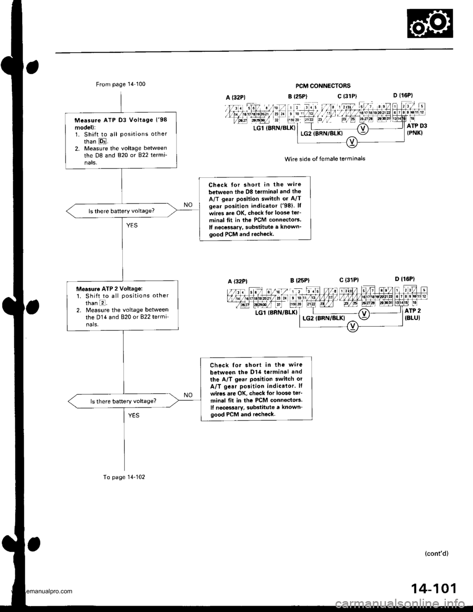
From page 14 100PCM CONNECTORS
B (2sP)c (31P}
' t d. , lll;;l';nl, :if
D t16P)
D {16P1
ATP D3{PNK)LGl (BRN/BLK}LG2IBRN/BLK)
Wire side of female terminals
B l25Plc (31P1
LGl IBRN/BLKI
A (32P1
Measure ATP D3 Vollage l'98model):1. Shift to all positions other
than E.2, Measure the voltage between
the D8 and 820 or 822 termi-
nals-
Check for shott in the wire
belween lh6 08 terminal and the
A/T gear posilion switch or A/Tgear position indicator ('98) lf
wires are OK, check lor loose ter-
minal tit in rhe PCM connectors.
ff necessary, substitute a known_good PCM and recheck.
ls there battery voltage?
Mearure ATP 2 voltage:1. Shift to all positions otherthan E.2. Measure the voltage betweenthe D14 and 820 or 822 termi
nals.
Check for short in the wire
between tho D1{ terminal and
the A/T gear posilion switch or
A/T gear position indicalor. lf
wiles are OK, check for loose t€r'
minal fit in the PCM connectors.It necessarv, substitute a known-good PCM and recheck.
To page 14-102
(cont'd)
14-101
www.emanualpro.com