lamp HONDA CR-V 1999 RD1-RD3 / 1.G Owner's Guide
[x] Cancel search | Manufacturer: HONDA, Model Year: 1999, Model line: CR-V, Model: HONDA CR-V 1999 RD1-RD3 / 1.GPages: 1395, PDF Size: 35.62 MB
Page 657 of 1395
![HONDA CR-V 1999 RD1-RD3 / 1.G Owners Guide
8. Set the control shaft to E] position. then install the
A,/T gear position switch on it.
CONTROL SHAFT
Install the AyT gear position switch cover and har-
ness clamp on the end cover.
Connect the HONDA CR-V 1999 RD1-RD3 / 1.G Owners Guide
8. Set the control shaft to E] position. then install the
A,/T gear position switch on it.
CONTROL SHAFT
Install the AyT gear position switch cover and har-
ness clamp on the end cover.
Connect the](/img/13/5778/w960_5778-656.png)
8. Set the control shaft to E] position. then install the
A,/T gear position switch on it.
CONTROL SHAFT
Install the Ay'T gear position switch cover and har-
ness clamp on the end cover.
Connect the A,/T gear position switch connector.
then install it on the connector bracket.
Turn the ignition switch ON (ll). Move the shift lever
through all gears, and check the AfI gesr position
switch synchronization with the A/T gear position
indicator.
9.
10.
11.
A/TGEARPOSMON A/T GEAR POSITIONINDICATOR INDICATOR'99 - 00 MODELS '�97 - 98 MOOELS
12, Start the engine. Move the shift lever through all
gears. and verify the following:
. The shift lever cannot be moved to E] position
from E position unless the shift lever is pulled.
. The engine will not start in any position other
than E or E.. The back-up lights come on when the shift lever
is in El position.
14-141
www.emanualpro.com
Page 666 of 1395
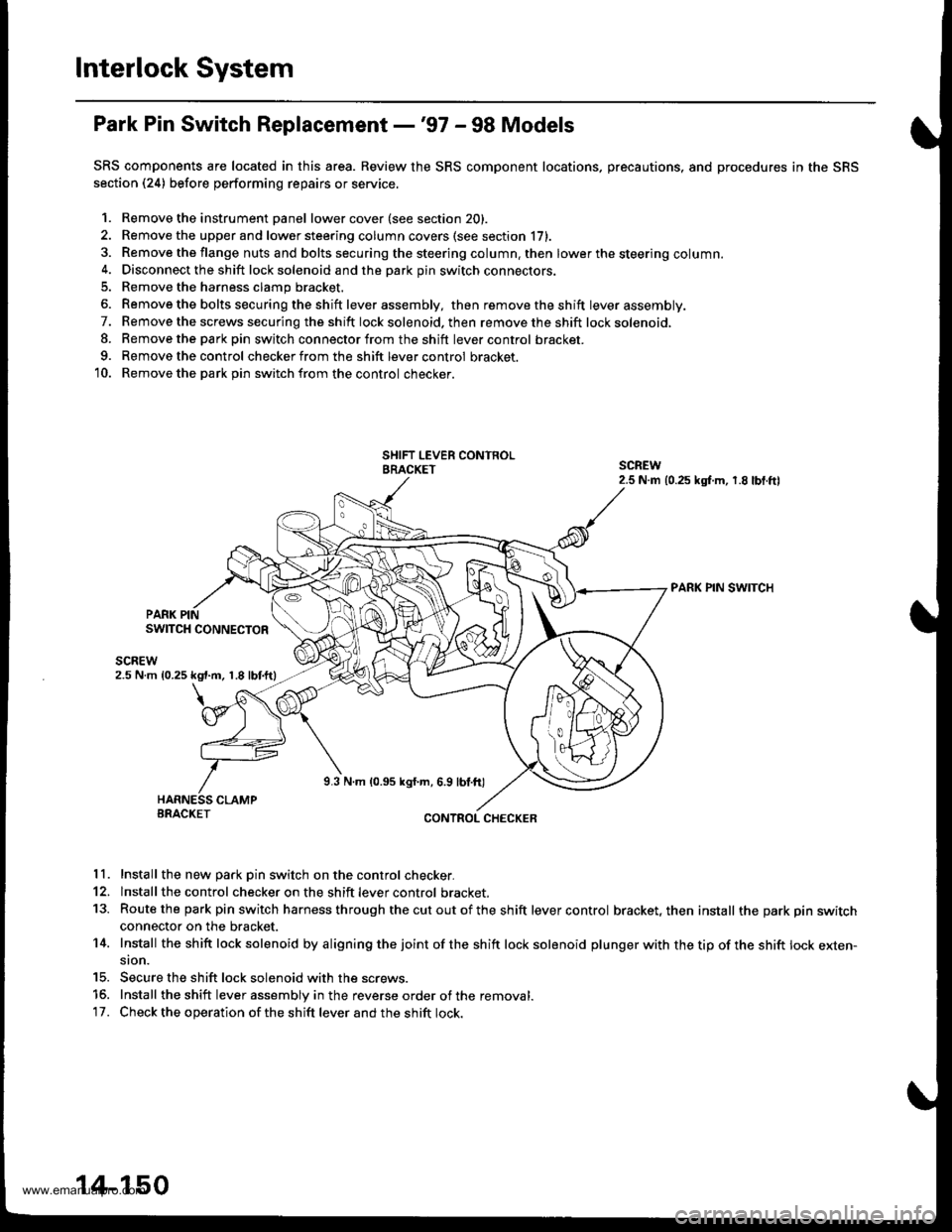
Interlock System
Park Pin Switch Replacement -'97 - 98 Models
SRS components are located in this area. Review the SRS component locations, precautions, and procedures in the SRS
section (24) before performing repairs or service.
1. Remove the instrument Danel lower cover (see section 20).
2. Remove the upper and lower steering column covers (see section li,.
3. Remove the flange nuts and bolts securing the steering column. then lower the steering column.4. Disconnect the shift lock solenoid and the park pin switch connectors.
5. Remove the harness clamp bracket.
6. Remove the bolts secu ring the shift lever assembly, then removetheshift lever assembly.
7. Remove the screws securing the shift lock solenoid. then remove the shift lock solenoid,
8. Remove the parkpin switch connector from the shift lever control bracket.
9. Remove the control checker from the shift lever control bracket.
10. Remove the park Din switch from the control checker.
PARK PIN SWITCH
PARK PINSWITCH CONNECTOR
scnEw2.5 N m 10.25 kgt.m, 1.8 lbtftl
9.3 N.m 10.95 kgf.m, 6.9 lbl.ft)
BRACKETCONTROL CHECKER
11. Install the new Dark Din switch on the control checker.
12. lnstall the control checker on the shift lever control bracket.
13. Routethe park pin switch harness through thecutoutofthe shift lever control bracket, then install the park pin switchconnector on the bracket.
14. Install the sh ift lock solenoid by a ligning the joint of the sh ift lock solenoid plu nger with the tip of the shift lock exten-sion.
15. Secure the shift lock solenoid with the screws.
15. Install the shift lever assembly in the reverse order of the removal.'17. Check the operation of the shift lever and the shift lock.
14-150
www.emanualpro.com
Page 667 of 1395
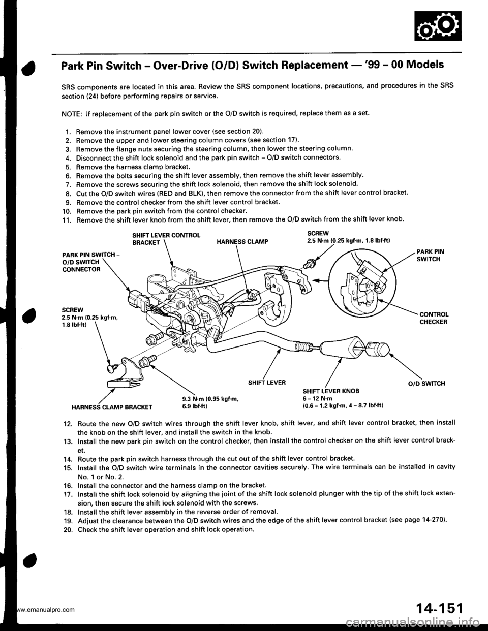
Park Pin Switch - Over-Drive (O/Dl Switch Replacement -'99 - 00 Models
SRS components are located in this area. Review the SRS component locations, precautions, and procedures in the SRS
section {24) before performing repairs or service.
NOTE: lf replacement of the park pin switch or the O/D switch is required. replace them as a set.
1. Remove the instrument panel lowercover(see section 20).
2. Remove the upper and lower steering column covers (see section 17).
3. Remove the flange nuts securing the steering column. then lower the steering column.
4. Disconnect the shift lock solenoid and the park pin switch - O/D switch connectors
5. Remove the harness clamp bracket.
6. Remove the bolts securing the shift lever assembly, then remove the shift lever assembly.
7. Remove the screws securing the shift lock solenoid, then remove the shift lock solenoid.
8. Cut the O/D switch wires (REDand BLK),then remove the con nector from the shift lever control bracket
9. Remove the control checker from theshift lever control bracket
10. Remove the oark oin switch from the control checker.
11. Remove the shift lever knob from the shift lever, then remove the O/D switch from the shift lever knob.
SCREW2.5 N.m 10.25 kgtm, 1.8lbf,ft)SHIFT LEVER CONTROLBRACKET
PARK PIN SWITCH -
o/D swlTcHCONNECTOR
2.5 N.m (0.25 kgt m,1.8 tbf.fr)
HABNESS CLAMP BRACKET
9.3 N.m 10.95 kgl.m.6.9 tbf ft)
SHIFT LEVER KNOB6-12N,m{0.6 - 1.2 kgt.m.4 - 8.7 lbf ftl
SHIFT LEVERo/o swlTcH
12. Route the new O/D switch wires through the shift lever knob, shift lever, and shift lever control bracket, then install
the knob on the shift lever, and install the switch in the knob.
13. Install the new park pin switch on the control checker, then install the control checker on the shift lever control brack-
et.
14. Routethe parkpin switch harnessthroughthecutoutoftheshift lever control bracket.
15. Install the O/D switch wire terminals in the connector cavities securely. The wire terminals can be installed in cavity
No. 1 or No.2.
16, Install the connector and the harness clamp on the bracket.
17. tnstall the shift lock solenoid by aligning the joint ot the shift lock solenoid plu nger with the tip of the shift lock exten-
sion, then secure the shift lock solenoid with the screws,
18. lnstall the shift lever assemblv inthe reverse order of removal.
19. Adjust the clearance between the O/D switch wires and the edge of the sh ift lever control bracket (see page 14-270).
20. Check the shift lever operation and shift lock operation.
14-151
www.emanualpro.com
Page 685 of 1395

Transmission
Removal
@
2.
'1.
Make sure lifts. iacks, and safety stands aro placed
properly, and hoist brackets are attached to the col-
rest position on the engine lsee section 11.
Apply th€ parking brake and block the r€ar wheels,
so vehicls will noi roll off the stands and fall on you
while working under it.
NOTE: Use fender covers to avoid damaging painted
surfaces.
Disconnect the negative terminal, then disconnect
the positive terminal from the battery.
Remove the intake air duct and the air cleaner hous-
ing assembly,
Remove the starter cables. Remove the harness
clamp from the clamp bracket.
5.
STARTERCABLES
Remove the transmission ground cable terminal
and the radiator hose clamp lrom the transmission
hanger.
Disconnect the lock-up control solenoid valve con-
nector, then remove the harness clamp from the
clamp bracket.HARNESS CLAMP
RADIATOR HOSECLAMP
CONTROLSOLENOID VALVECONNECTOR
CLAMP
6. Disconnect the vehicle speed sensor (VSS), the coun-
tershaft speed sensor, and the A/T gear position
switch connectors.
A/T GEAR POSITIONSWITCH CONNECTOR
VEHICLE SPEEDSENSOR |VSS'
CONNECTORBfiACKET
SPEED SENSORCONNECTOR
7. Remove the transmission housing mounting bolts.
MOUNTING BOLTS
(cont'd)
14-169
www.emanualpro.com
Page 691 of 1395
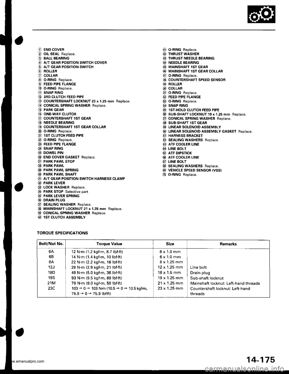
O END COVER
O olL SEAL Replace.
O BALL BEARING
@ A/T GEAR PoSITIoN swITcH coVER
€) A/T GEAn PosrloN swrrcH
@ ROLLER
O coLLARG) o-RING Replace.{9) FEED PIPE FLANGE
@ O-RING Replace.
O SNAP RING
@ 3RD CLUTCH FEED PIPE(D CoUNTERSHAFT LOCKNUT 23 x 1.25 mm Replace.(} coNtcAL SPR|NG WASHER Reptace.
@ PARK GEAR@ ONE.WAY CLUTCH(, COUNTENSHAFT lST GEAR(D NEEOLE BEARING(O COUNTERSHAFT lST GEAR COLLAR
@ o-RING Reptace.
@ lST CLUTCH FEED PIPE
@ O-RING Reptace.
@} FEEO PIPE FLANGE
@ SNAP RING
@ DOWEL PIN
@ END coVER GASKET Feplace.
@ PARK PAWL SToP@ PARK PAWL
@ PARK PAWL SPRING
@ PARK PAWL SHAFT
O} A/T GEAR POSITION SWITCH HARNESS CLAMP
@ PARK LEVER
@ LOCK WASHER Replace.
@ PARK STOP Selective part
@ PARK LEVER SPRING@ DRAIN PLUG
O SEALING WASHER Reptace.
@) MAINSHAFT LOCKNUT2l x 1.25 mm Replace.@ CONICAL SPRING WASHER Replace.@ lST CLUTCH ASSEMBLY
TOROUE SPECIFICATIONS
i!, O-RING Replace.
@ THRUST WASHER
@ THRUST NEEDLE BEARING@ NEEDLE BEARING
@ MAINSHAFI 1ST GEAR@ MAINSHAFT 1sT GEAR coLLAR
@ o-RING Replace.
6!, COUNTERSHAFT SPEED SENSOR@ ROLLER
@) COLLAR@ o-RtNG Replace.
6A FEEo PIPE FLANGE
@ o-RtNG Reptace.
@ SNAP R|NG
@ IST.HOLD cLUTcH FEED PIPE@ SUB-SHAFT LOCKNUT 19 x 1,25 mm Reptace.O coNtCAL SPR|NG WASHER Reptace.E! SUB.SHAFT lST GEAR€} LINEAR SOLENOID ASSEMBLY
@ LTNEAR soLENotD aSSEMBLy GASKET Reptace.
@ HARNESS BBACKET
@ SEALING WASHERS Feptace.
@ ATF COOLER LINE
@ LIN€ BoLT
@ ATF DIPSTICK
@ ATF COOLER LINE
@ LINE BoLT@ SEALING WASHERS Reptace.@ VEHICLE SPEED sENsoR (vss)
@ o-RtNG Beptace.
Bolt/Nut No.Torque ValuoSizeRemarks
6B
8A
12J
18D
19S
21M
23C
'12 N'm ('1.2 kgf.m,8.7 lbf.ft)
14 N.m (1.4 kgf.m, 10lb{.ft}
22 N.m 12.2 kgf.m, 16 lbf.ft)
28 N'm (2.9 kgf.m,21 lbf.ft)
49 N.m (5.0 kgf.m,36 lbf'ft)
93 N'm {9,5 ksim.69 lbf.ft)
78 N.m {8.0 kgnm,58 lbf.ft)
103* 0- 103 N{n {10.5* 0+ 10.5 kgfn,
75.9-0-75.9 lbf{t)
6x 1.0 mm
6x1.0mm
8 x 1.25 mm
12 x 1.25 mm
18 x 1.5 mm
19 x 1.25 mm
21 x 1.25 mm
23 x 1.25 mm
Line bolt
Drain plug
Sub-shaft locknut
Mainshaft locknut: Left-hand threads
Countershaft locknut: Left-hand
threads
14-175
www.emanualpro.com
Page 693 of 1395
![HONDA CR-V 1999 RD1-RD3 / 1.G Owners Guide
r] REVERSE IDLER GEAR SHAFT/HOLDERA N€EDLE BEARING
..] TRANSMISSION HOUSING
al TRANSMISSION HOUSING OIL SEAL Replace.g SET BING.80 mm Selecrive part
O REVERSE GEAR COLLABE couNTERSHAFT REVERSE GEA HONDA CR-V 1999 RD1-RD3 / 1.G Owners Guide
r] REVERSE IDLER GEAR SHAFT/HOLDERA N€EDLE BEARING
..] TRANSMISSION HOUSING
al TRANSMISSION HOUSING OIL SEAL Replace.g SET BING.80 mm Selecrive part
O REVERSE GEAR COLLABE couNTERSHAFT REVERSE GEA](/img/13/5778/w960_5778-692.png)
r] REVERSE IDLER GEAR SHAFT/HOLDER'A N€EDLE BEARING
..] TRANSMISSION HOUSING
al TRANSMISSION HOUSING OIL SEAL Replace.g SET BING.80 mm Selecrive part
O REVERSE GEAR COLLABE couNTERSHAFT REVERSE GEAB
.9,] NEEDLE BEARINGi9 LOCK WASHER Replace..1!i REVERSE SHIFT FORKO REVERSE SELECToRiJ. REVERSE SELECTOR HUBii' COUNTERSHAFT 4TH GEAR.14 NEEDLE BEARINGiD D|STANCE coLLAR,28 mm Selective part(i3 COUNTERSHAFT 2NO GEABi7-] THRUST NEEDLE BEARING(10 COUNTERSHAFT 3RD GEAR(9 NEEDLE BEARINGE9 COUNTERSHAFI3RD GEAB COLLAR.li THRUST NEEDLE BEARING.?) SPLINEO WASHER,,O 3RD CLUTCH ASSEMBLY
€1 O-RING Beplace.i23 COUNTERSHAFT
4i SHIFT CONTROL SOLENOID COVER
?Z] HARNESS CLAMP BRACKET
?9] SHIFT CONTROL SOLENOID VALVE A/B ASSEMBLY
8 HARNESS CLAMP BRACKET
GI SHIFT CONTROL SOLENOID VALVE FILTER/GASKET
(4 MAINSHAFT 2ND GEARi49 NEEDLE BEARING
@ THRUST NEEDLE BEARING(49 MAINSHAFT
@r SEAL|NG R|NG,35 mm
O SEALING RING,29 mm
@ NEEDLE BEARING
.49 SET RING
€) lST.HOLD CLUTCH ASSEMBLY
O o-RING Replace.6E THRUST WASHER
€9 THRUST NEEDLE BEARING
6' NEEDLE EEARING
€ir SUB-SHAFT 4TH GEAR
6 THRUST NEEDLE BEARING
@ SUB.SHAFT 4TH GEAR COLLAR@ sUB-sHAFf
6I NEEDI-E B€ARING STOP
@ NEEDLE BEARING(6t ATF GUIDE CAP Replace.(64 TRANSMISSION HANGEB
@ BREATHER CAP
i@ MAINSHAFT SPEED SENSOR
6i O-RING Replace.
6D REVERSE IDLER GEAR
@r DOWEL PlN, 14 x 25 mm.6d SNAP RINGS
QlI SUB.SHAFT TRANSMISSION HOUSING BEARING
E) MAINSHAFT TRANSMISSION HOUSING BEABING.2, COUNTERSHAFI TRANSMISSION HOUSINGBEARING
@[E
t,n9t0@)@),lD
04
@
@@:���������������.ro)
ai
Replace-SNAP RINGTHRUST WASHEBTHRUST NEEDLE BEARINGMAINSHAFT 4TH GEARNEEDLE BEARINGSTHRUST NEEDLE BEARINGMAINSHAFT 4TH GEAB COLLAR2NO/4TH CLUTCH ASSEMBLYO-RING Replace.THRUST WASHER,36.5 x 55 mm Selective partTHRUST NEEOLE BEARING
DOWEL PlN, 14 x 25 mmCONNECTOR BRACKETATF MAGNETDOWEL PlN, 14 x 20 mmTRANSMISSION HOUSING GASKET Replace.DIFFERENTIAL ASSEMBLYDOWEL PlN, 10 x 12 mmO-RING Replace.TRANSFER ASSEMBLYTOROUE CONVERTER HOUSING OIL SEAL Replace.TOROUE CONVERTER HOUSING
TOROUE SPECIFICATIONS
Bolt/Nut No.Torque ValueSizeRgmarks
6A
6B
10A
12 N.m (1.2 kgf.m,8.7 lbf.ft)
14 N.m (1.4 kgf.m, 10 lbift)
44 N.m (4.5 kgf.m,33 lbf.ft)
6x 1.0 mm
6x 1.0 mm
10 x 1.25 mm
14-177
www.emanualpro.com
Page 699 of 1395
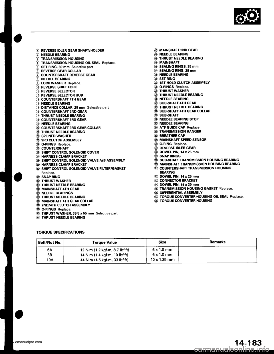
oatl,6
@!.,
ao6l
@o@@@@@o@@@)@@@@@@@@@@)
@@@@)@@@@@@@
REVERSE IDLER GEAR SHAFT,/HOLDERNEEOLE BEARINGTRANSMISSION HOUSINGTRANSMISSION HOUSING OIL SEAL R€place.SET RING,80 mm Selective part
REVERSE GEAR COLLARCOUNTERSHAFT REVERSE GEARNEEDLE BEARINGLOCK WASHER Replace.REVERSE SHIFT FORKREVERSE SELECTORREVERSE SELECTOR HUBCOUNTERSHAFT 4TH GEARNEEDLE BEARINGDISTANCE COLLAR,28 mm Selective pan
COUNTERSIIAFT 2ND GEARTHRUST NEEDLE BEARINGCOUNTERSHAFT 3RD GEARNEEDLE AEARINGCOUNTERSHAFT 3RD GEAR COLLARTHRUST NEEOLE BEARINGSPLINEO WASHER3RD CLUTCH ASSEMBLYO-RINGS Replace.COUNTERSHAFTSHIFT CONTROL SOLENOID COVERHARNESS CLAMP BRACKETSHIFT CONTROL SOLENOID VALVE A/B ASSEMBLYHARNESS CLAMP BRACKETSHIFT CONTROL SOLENOID VALVE FILTER/GASKETReplace.SNAP RINGTHRUST WASHERTHRUST NEEDLE BEARINGMAINSHAF ,ITH GEARNEEDLE BEARINGSTHRUST NEEDLE BEARINGMAINSHAFT 4TH GEAR COLLAR2ND/4TH CLUTCH ASSEMBLYO-RINGS ReDlace.THRUST WASHER,36.5 x 55 mm Selective part
THRUST NEEDLE BEARING
MAINSHAFT 2ND GEARNEEDLE BEARINGTHRUST NEEOLE BEARINGMAINSHAFTSEALING RINGS,35 mmSEALING RING. 29 mmNEEDLE BEARINGSET RINGlST-HOLD CLUTCH ASSEMSLYO-RINGS Replace.THRUST WASHERTHRUST NEEDLE BEARINGNEEDLE BEARINGSUB.SHAFT 4TH GEARTHRUST NEEDLE BEARINGSU&SHAFT,ITH GEAR COLLARSUB.SHAFTNEEDLE BEARING STOPNEEDLE BEARINGATF GUIDE CAP Replace.TRANSMISSION HANGERBREATHER CAPMAINSHAFT SPEED SENSORO-RING Reolace.REVERSE IDI.fR GEARDOWEL PlN, lil x 25 mmSNAP RINGSSU&SHAFT TRANSMISSION HOUSING AEARINGMAINSHAFT TRANSMISSION HOUSING BEARINGCOUNTERSHAFT TNANSMISSION HOUSINGBEABINGDOWEL PlN, 14 x 25 mrnCONNECTOR BRACKETDOWEL PlN, 14 x 20 mmTRANSMISSION HOUSING GASKET Replace.DIFFERENTIAL ASSEMBLYTOROUE OONVERTER HOUSING OIL SEAL Replace.TOROUE CONVERTER HOUSING
@@@@@@@@@@@@@@@@@@@@@@@)@@@@@@@
@@@@@@@
TOROUE SPECIFICATIONS
Boli/Nut No.Torque ValueSizeRemarks
6B
10A
12 N.m (1.2 kgf.m,8.7 lbf.ft)'14 N.m (1.4 kgim, 10 lbf'ft)
44 N.m (4.5 kgim, 33 lbf.ft)
6x 1.0 mm
6x1.0mm
10 x '1.25 mm
14-1A3
www.emanualpro.com
Page 702 of 1395
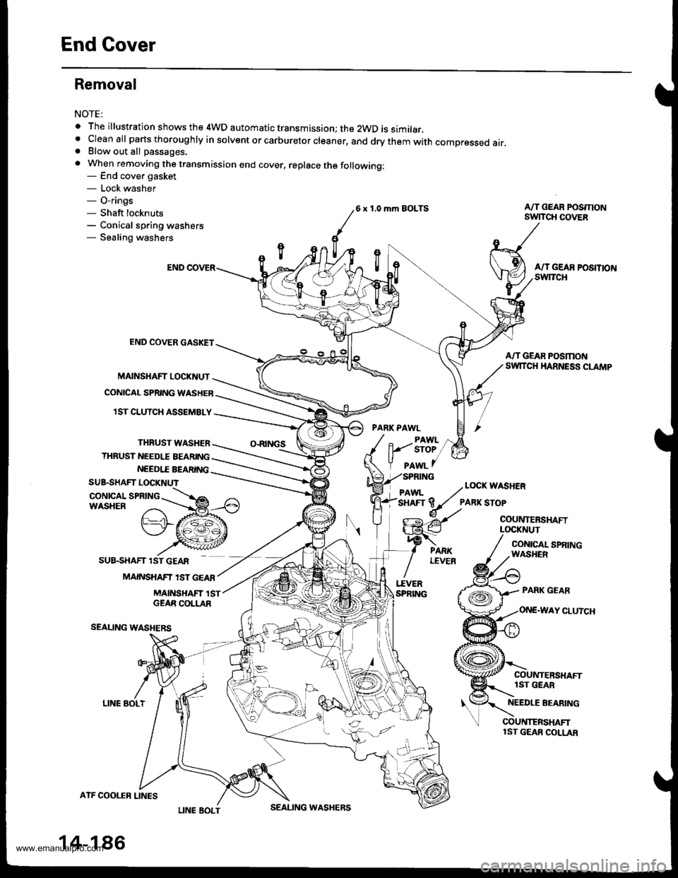
End Cover
Removal
NOTE:
o The illustration shows the 4WD automatic transmission; the 2WD is similar.. cleanall parts thoroughly in solvent or carburetor cleaner, and drythem with compressed air.. Blow out all passages.
. When removing the transmission end cover, replace the following:- End cover gasket- Lock washer- O-rings- Shaft locknuts- Conical spring washers- Sealing washers
END COVER GASKET
MAINSHAFT LOCKNUT
CONICAL SPRING WASHER
6 x 1 .0 rhm EOLTS
PARK PAWL
A/T GEAR POSMONSwlTCH COVER
NEEDI.T BEARING
SUB.SHAFT LOCKNUT
CONICAL SPRINGWASHER
LINE AOLT
ATF COOI.f B LINES
14-186
PAwL 7// Locx wASHER
'sHAFr 9/ ?ARK srop
o-- Ay' couNTERsHAFr
G-€ LocKNUr!€ / ..t,"o, "oo
A/T GEAR POSMONSW|TCH HARNESS CLAMP
CONICAL SPRINGWASHCR
A/T GEAR POSITION
PARK GEAR
Y CLUTCH
lST GEAR
NEEDLE BEARING
1ST CLUTCH ASSEMBLY
THRUST WASHER
THRUST NEEDLE AEARING
O.RINGS
\\
SUB.SHAFT 1ST GEAR
MAINSHAF? 'ST GEAR
MAINSHAFT 1STGEAR COLLAR
SEALING WASHERS
!€'-l
I"EVERSPRING
COUNTERSHAFTlST GEAR COLLAR
PAWL
lt1/ sroe
Y plwl f
L/'SPRING
LOCKNUT
LINE BOLTSEALING WASHERS
www.emanualpro.com
Page 703 of 1395
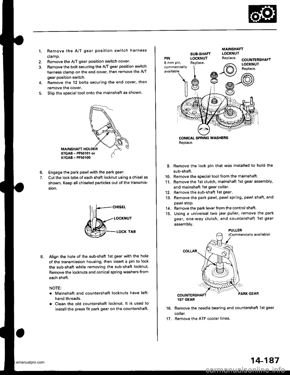
1. Remove the A/T gear position switch harness
cramp.
Remove the y'VT gear position switch cover.
Remove the bolt securing the ly'T gear position switch
harness clamp on the end cover, then remove the A/T
gear position switch.
Remove the 12 bolts securing the end cover. then
remove the cover.
Slip the special tool onto the mainshaft as shown.
6. Engage the park pawl with the park gear.
7. Cut the locktabs of each shaft locknut using a chisel as
shown. Keep all chiseled particles out of the transmis-
ston.
M=tt"
Align the hole of the sub-shaft 1st gear with the hole
of the transmission housing. then insert a pin to lock
the sub-shaft while removing the sub-shaft locknut.
Remove the locknuts and conical spring washers from
each shaft.
NOTE:
Mainshaft and countershaft locknuts have left-
hand threads.
Clean the old countershaft locknut. lt is used to
install the press fit park gear on the countershaft.
MAINSHAFT
PIN8 mm pin,
commercially
SUB-SHAFTLOCKNUTReplace.COUNTERSHAFTLOCKNUTReplace.
CONICAL SPNING WASHERSReplace.
9. Remove the lock pin that was installed to hold the
sub-shaft.
10. Remove the special tool from the mainshaft.
11. Remove the 1st clutch, mainshaft 1st gear assembly,
and mainshaft 1st gear collar.'12. Remove the sub-shaft 1st gear.
13. Remove the park pawl, pawl spring, pawl shaft. and
pawl stoP.
14. Remove the park lever from the control shaft.
15. Using a universal two jaw puller, remove the park
gear, one-way clutch, and countershaft 1st geal
assemblv.
{Commercially available)
1SY GEAR
Remove the needle bearing and countershaft 1st gear
co ar.
Remove the ATF cooler lines,
LOCKNUTReplace.
2\
Irot)
PULLER
11.
14-187
www.emanualpro.com
Page 773 of 1395
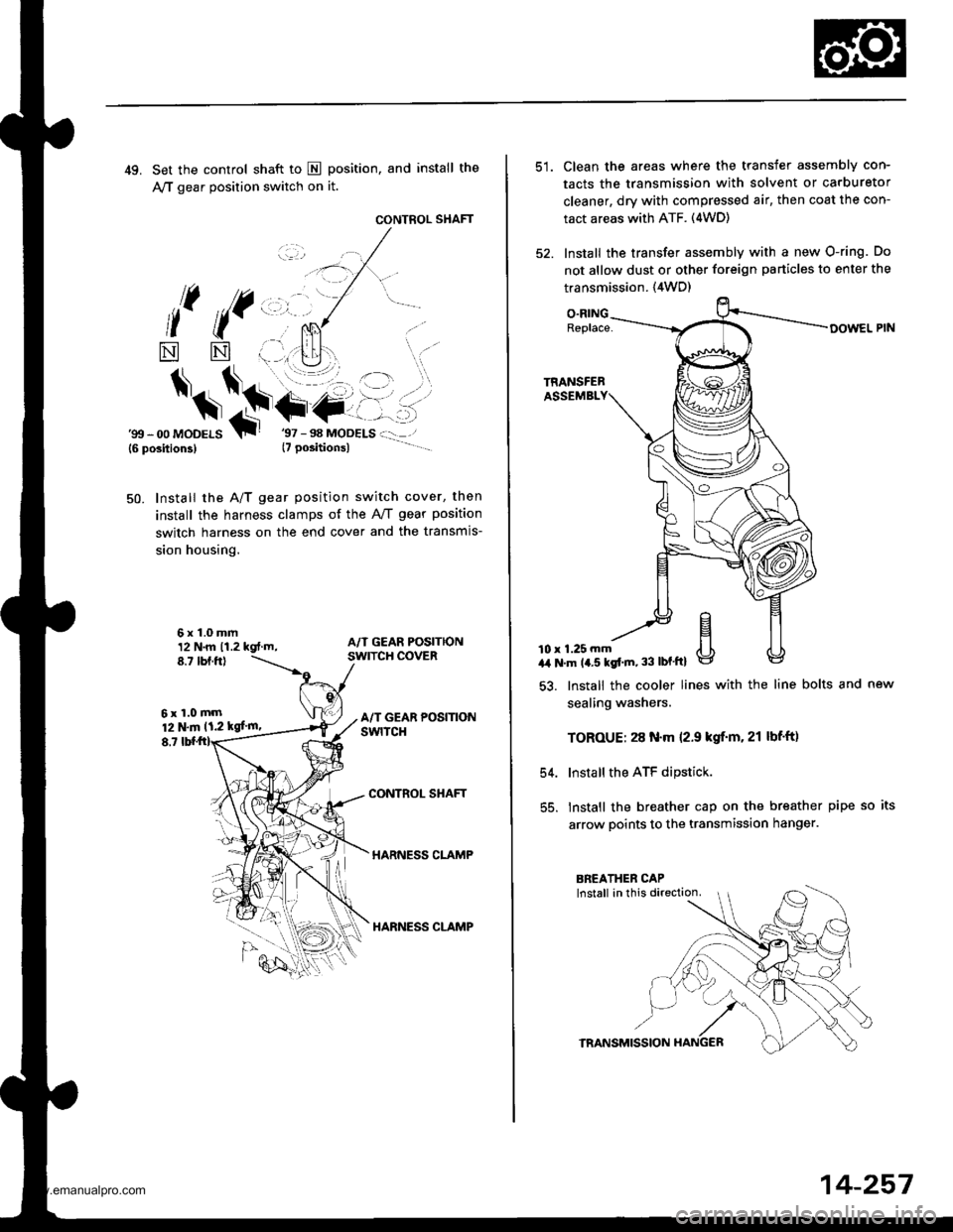
49. Set the control shaft to E position, and install the
A,/T gear position switch on it.
CONTROL SHAFT
l( ((,,, ,.
*
$*\.t+-
NN
6x1.0mm12 N.m 11.2 kgt.m,8.7 tbf.ftl
6xl.0mm12 N.m 11.2 kgf'm,
8,7
'gtt - 00 MoDELS{6 position3}T
Install the A/T gear position switch cover, then
install the harness clamps of the AviT gear position
switch harness on the end cover and the transmis-
sion housing.
50.
CONTROL SHAFT
HARNESS CLAMP
HARNESS CLAMP
Clean the areas where the transfer assembly con-
tacts the transmission with solvent or carburetor
cleaner, dry with compressed air, then coat the con-
tact areas with ATF. (4WD)
Install the transfer assembly with a new O-ring. Do
not allow dust or other foreign particles to enter the
transmission. {4WD)
O.RINGReplace-
10 r 1.25 mma,a N'm 14.5 kgt'm, 33 lbf'ftl
54.
55.
lnstall the cooler lines with the line bolts and new
sealing washers.
TOROUE: 28 N.m 12.9 kgif'm. 21 lbf'ft)
Install the ATF dipstick.
lnstall the breather cap on the breather pipe so its
arrow points to the transmission hanger.
TRANSMISSION
14-257
www.emanualpro.com