lamp HONDA CR-V 1999 RD1-RD3 / 1.G Repair Manual
[x] Cancel search | Manufacturer: HONDA, Model Year: 1999, Model line: CR-V, Model: HONDA CR-V 1999 RD1-RD3 / 1.GPages: 1395, PDF Size: 35.62 MB
Page 1140 of 1395
A/C FilterHeater Unit
Replacement
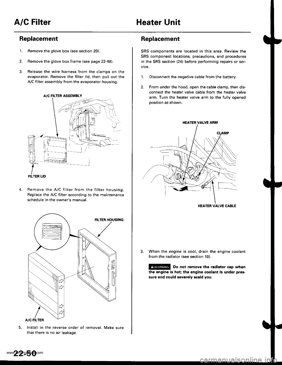
1.Remove the glove box (see section 20).
Remove the glove box frame {see page 22-4A).
Release the wire harness from the clamps on the
evaporator. Remove the filter lid, then pull out the
,VC filter assembly from the evaporator housing.
A/C FILTER ASSEMELY
Remove the A/C filter from the filter housing.
Replace the Ay'C filter according to the maintenance
schedule in the owner's manual.
Install in the reverse order of removal. Make sure
that there is no air leakage.
22-50
Replacement
SRS components are located in this area. Review the
SRS component locations, precautions, and procedures
in the SRS section {24) before performing repairs or ser-
1. Disconnect the negative cable from the battery.
2. From under the hood, open the cable clamp, then dis-
connect the heater valve cable from the heater valve
arm. Turn the heater valve arm to the fullv ooened
oosition as shown.
When the engine is cool, drain the engine coolant
from the radiator (see section 10).
@ Do not remove the rldiator cap when
the engine is hot; the engine coolant is under pres-
sure and could sevo.ely scald you.
HEATER VALVE ARM
HEATER VALVE CABLE
www.emanualpro.com
Page 1141 of 1395
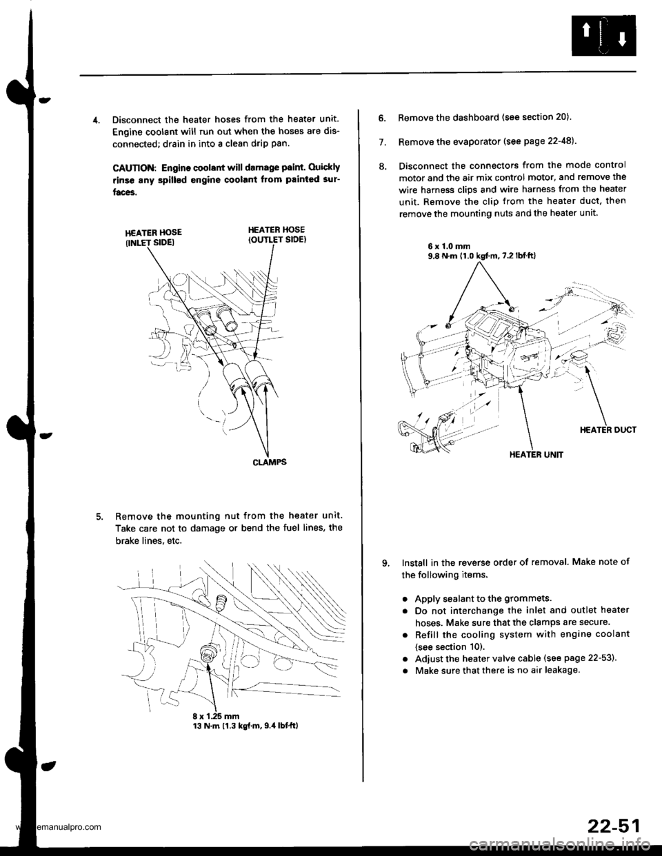
4. Disconnect the heater hoses from the heater unit.
Engine coolant will run out when the hoses are dis-
connected; drain in into a clean drip pan.
CAUTION: Engino coolant will damage p8int. Ouickly
rinse any spill€d engine coolant Itom painted sur-
faces.
HEATER HOSEIOUTLET SIDE)
Remove the mounting nut from the heater unit.
Take care not to damage or bend the fuel lines, the
brake lines. etc.
CLAMPS
13 N.m 11.3 kg{.m,9.4 lbtftl
22-51
7.
ll.
Remove the dashboard (see section 20).
Remove the evaporator (see page 22-48).
Disconnect the connectors from the mode control
motor and the air mix control motor, and remove the
wire harness clips and wire harness from the heater
unit. Remove the clip from the heater duct, then
remove the mounting nuts and the heater unit
6x1.0mm9,8 N.m (1.0 kgt m,7.2lblft)
qInstall in the reverse order of removal. Make note of
the following items.
a
a
a
a
Apply sealant to the grommets.
Do not interchange the inlet and outlet heater
hoses. Make sure that the clamps are secure.
Refill the cooling system with engine coolant
{see section 10).
Adiust the heater valve cable (see page 22-53).
Make sure that there is no air leakage.
HEATER UNIT
www.emanualpro.com
Page 1142 of 1395
Heater Unit
Overhaul
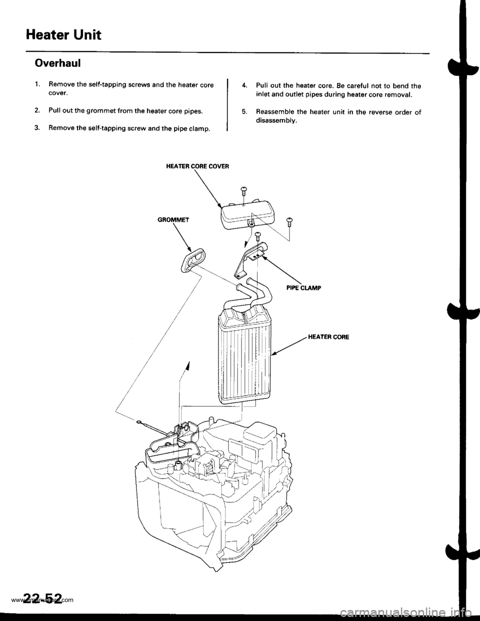
1. Remove the self-tapping screws and the heater corecover.
Pull out the grommet from the heater core pipes.
Remove the self-tapping screw and the pipe clamp.
HEATER CORE COVER
Pull out the heate. core. Be careful not to bend the
inlet and outlet pipes during heater core removal.
Reassemble the heater unit in the reverse order of
disassemblv.
HEATER CORE
22-52
www.emanualpro.com
Page 1143 of 1395
Temperature Control
Adjustment
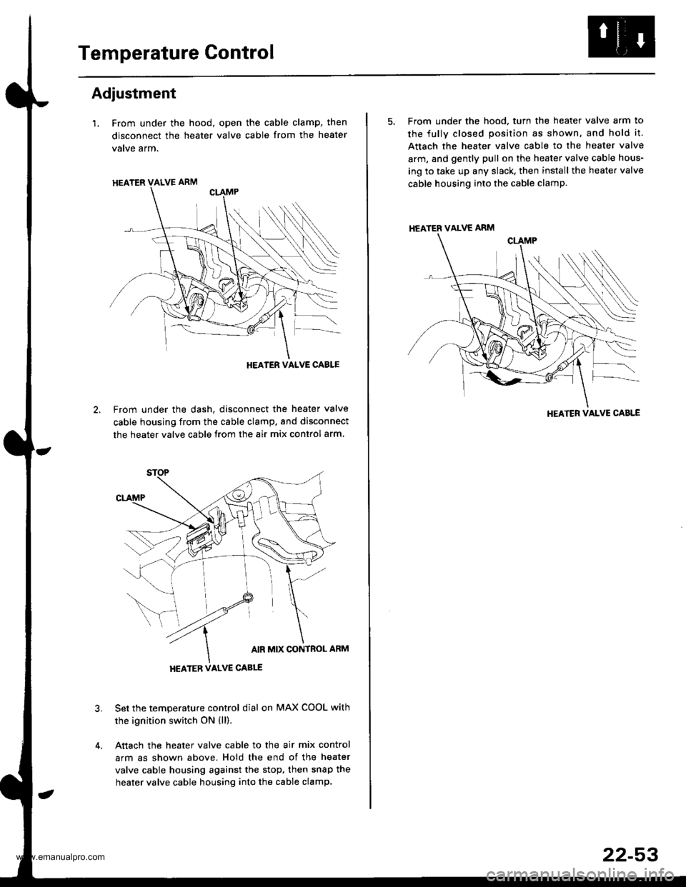
l. From under the hood, open the cable clamp, then
disconnect the heater valve cable from the heater
vatve arm.
From under the dash, disconnect the heater valve
cable housing from the cable clamp. and disconnect
the heater valve cable from the air mix contlol arm
Set the temperature control dial on MAX COOL with
the ignition switch ON (ll).
Attach the heater valve cable to the air mix control
arm as shown above. Hold the end of the heater
valve cable housing against the stop, then snap the
heater valve cable housing into the cable clamp.
HEATER VALVE ARM
HEATER VALVE CABLE
5. From under the hood. turn the heater valve arm to
the fullv closed position as shown, and hold it.
Attach the heater valve cable to the heater valve
arm, and gently pull on the heater valve cable hous-
ing to take up any slack, then install the heate. valve
cable housing into the cable clamp.
HEATER VALVE ARM
HEATER VALVE CABLE
22-53
www.emanualpro.com
Page 1157 of 1395
l-
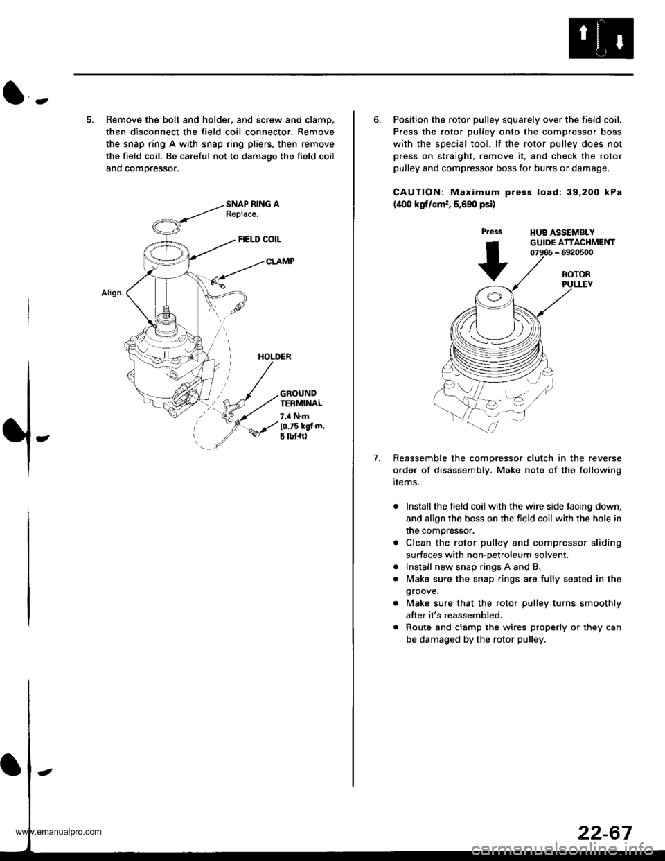
5. Remove the bolt and holder, and screw and clamp.
then disconnect the field coil connector. Remove
the snap ring A with snap ring pliers, then remove
the field coil. Be careful not to damage the field coil
and comoressor.
FIELD COIL
CLAMP
HOLDER
GROUNDTERMINAL
7,a N.m
10.75 kgt'm,5 tbt ftl
6. Position the rotor pulley squarely over the field coil.
Press the rotor pulley onto the compressor boss
with the special tool. lf the rotor pulley does not
press on straight, remove it, and check the rotor
pulley and compressor boss for burrs or damage.
CAUTION: Maximum pre3s load: 39,200 kPa
(400 kgf/cm,, 5,690 psi)
Press
+
HUB ASSEMBLYGUIDE ATTACHMENT07966 - 6920500
7.
ROTORPULLEY
Reassemble the comDressor clutch in the reverse
order of disassembly. Make note of the following
rrems.
Install the field coil with the wire side facing down,
and align the boss on the tield coil with the hole in
the compressor.
Clean the rotor pulley and compressor sliding
surfaces with non-oetroleum solvent.
lnstall new snap rings A and B.
Make sure the snap rings are fully seated in the
groove.
Make sure that the rotor pulley turns smoothly
after it's reassembled.
Route and clamp the wires properly or they can
be damaged by the rotor pulley.
a
a
www.emanualpro.com
Page 1217 of 1395
l-
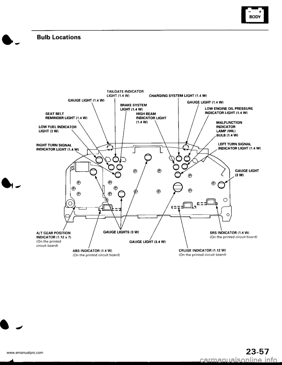
Bulb Locations
TAILGATE INDICATORLIGHT (,I.4 W) CHARGING SYSTEM LIGHT (1.4 WI
GAUGE LIGHT {1.4 WIGAUGE LIGHT I1,4 WIBRAKE SYSTEMLTGHT 11.4 WlLOW ENGINE OIL PRESSUREINDICATOR LIGHT {1./r W}SEAT BELTREMINDER LIGHT {1.' W'HIGH BEAMINDICATOR LIGHT
LOW FUEL INOICATOBLIGHT 13 WI
MALFUNCTIONINOICATORLAMP {MIL)BULB I1.4 WI
{1.4 Wl
RIGHT TURN SIGNALINDICATOR LIGHT I1.' WI
GAUGE LIGHTS 13 WI
LEFT TURN SIGNALINDICATOR LIGHT {1,4 W}
GAUGE LIGHT
t3 wl
SRS INDICATOR ('1./t W)(On the printed circuit board)
1,.
A/T GEAR POSITIONINDICATOR {1.12 x 7}(On the printed
circuit board)GAUGE LIGHT {3.' W}
ABS INDICATOR (1,4 W)
lOn the printed circuit board)cRutsE tNDtcAToR 11.r2 w)(On the printed circuit board)
f-= F -
J
23-57
www.emanualpro.com