HONDA CR-V 1999 RD1-RD3 / 1.G Workshop Manual
Manufacturer: HONDA, Model Year: 1999, Model line: CR-V, Model: HONDA CR-V 1999 RD1-RD3 / 1.GPages: 1395, PDF Size: 35.62 MB
Page 541 of 1395
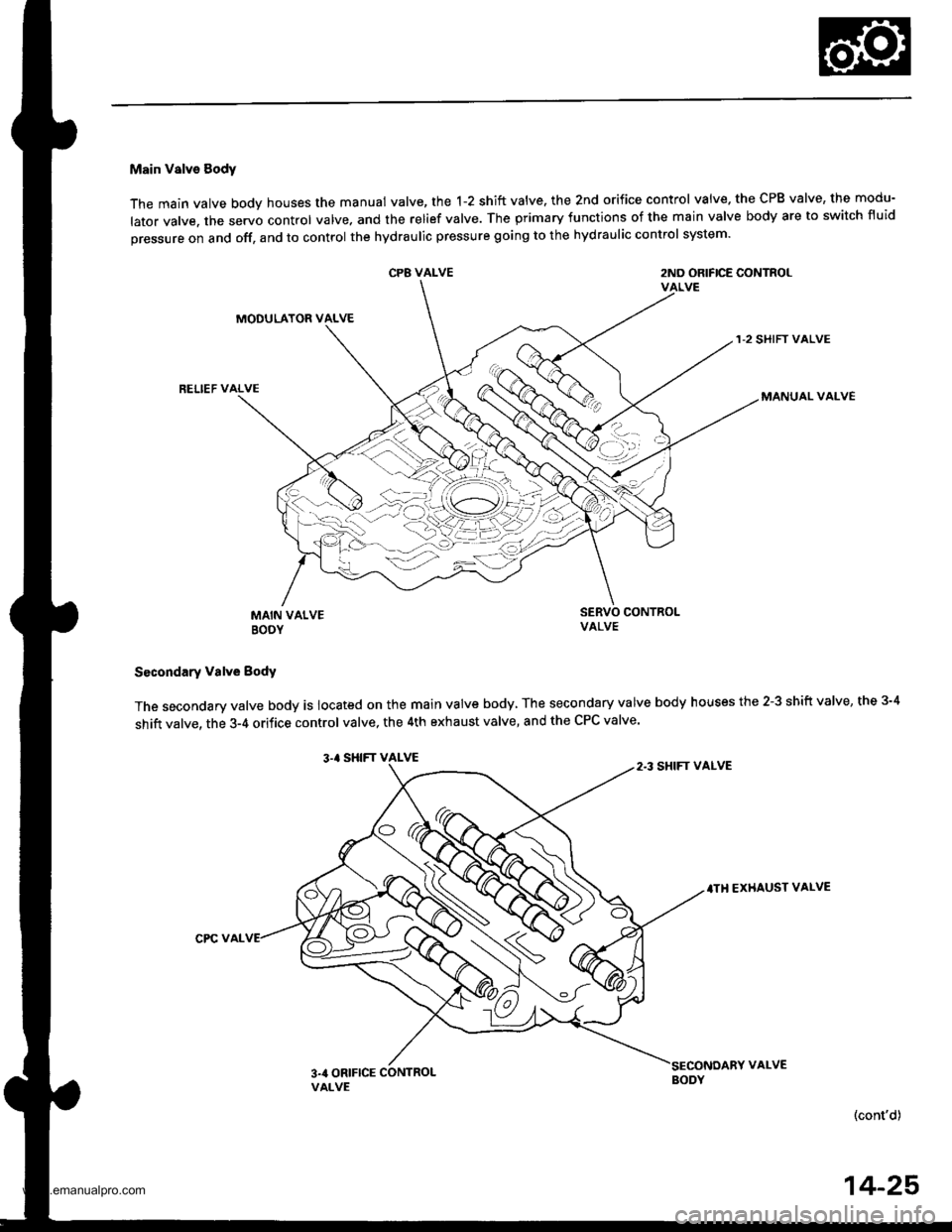
Main Valve Sody
The main valve body houses the manual valve, the 1-2 shift valve. the 2nd orifice control valve. the CPB valve, the modu-
lator valve. the servo control valve. and the relief valve. The primary functions of the main valve body are to switch fluid
pressure on and off, and to control the hydraulic pressure going to the hydraulic control system.
CP8 VALVE2ND ORIFICE CONTROLVALVE
MODULATOR VALVE
RELIEF VALVE
1-2 SHIFT VALVE
MANUAL VALVE
MAIN VALVEBOOY
SERVO CONTROI-VALVE
Secondary valve Body
The secondary valve body is located on the main valve body, The secondary valve body houses the 2-3 shift valve, the 3-4
shift valve, the 3-4 orifice control valve, the 4th exhaust valve, and the CPC valve'
3.' SHIFT VALVE
.TH EXHAUST VALVE
CPC VAL
(cont'd)
14-25
2.3 SHIFT VALVE
3na ORIFICE CONTROLVALVE
VALVE
www.emanualpro.com
Page 542 of 1395
Description
Hydraulic Control (cont'd)
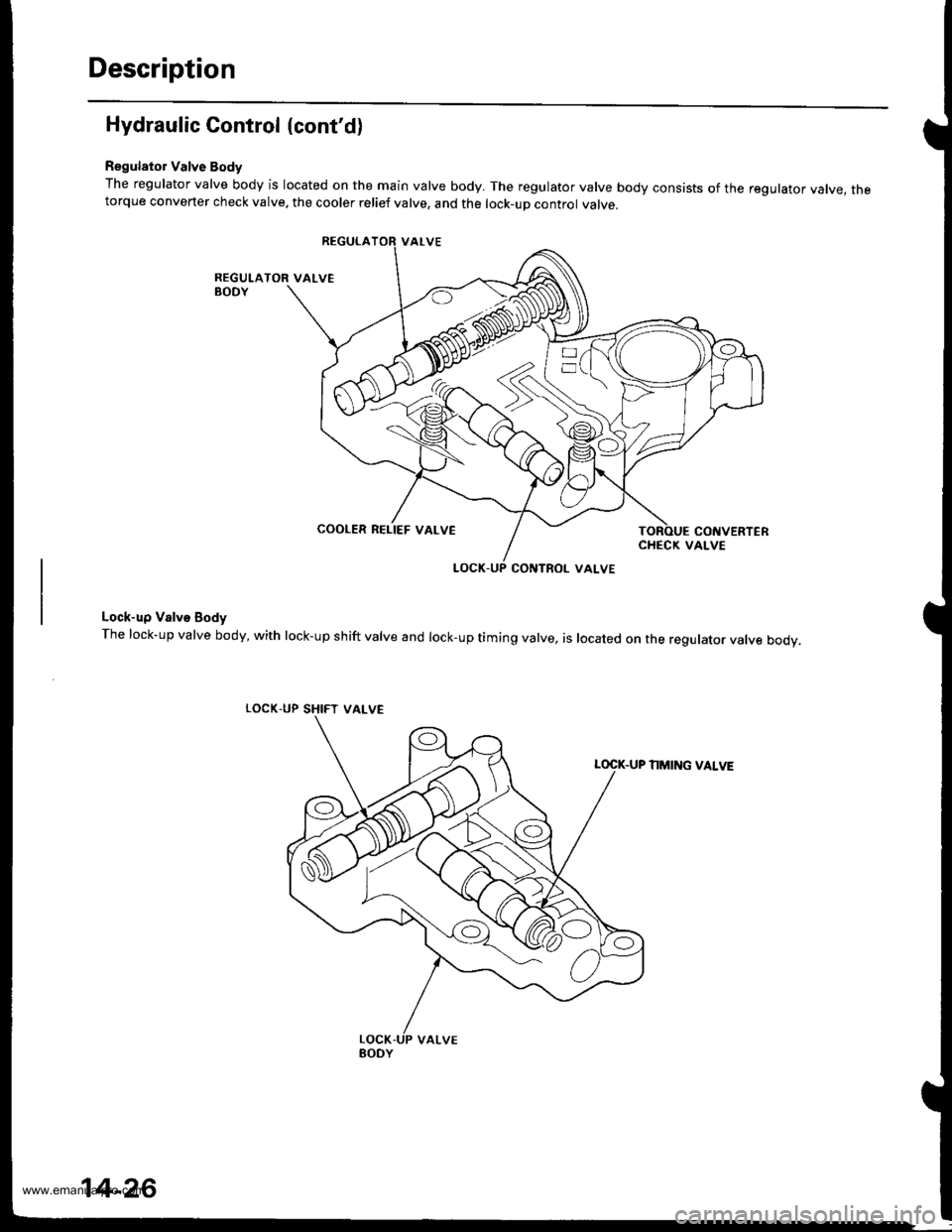
Regulator Valve Body
The regulator valve body is located on the main valve body. The regulator valve body consists of the regulator vatve, thetorque converter check valve. the cooler relief valve, and the lock-up control valve.
Lock-up Valve Body
The lock-up valve body, with lock-up shift valve and lock-up timing valve, is located on the regulator valve body.
LOCK.UP SHIFT
NMING VALVE
COOLER RELIEF VALVE
VALVE
14-26
www.emanualpro.com
Page 543 of 1395
Regulator Valve
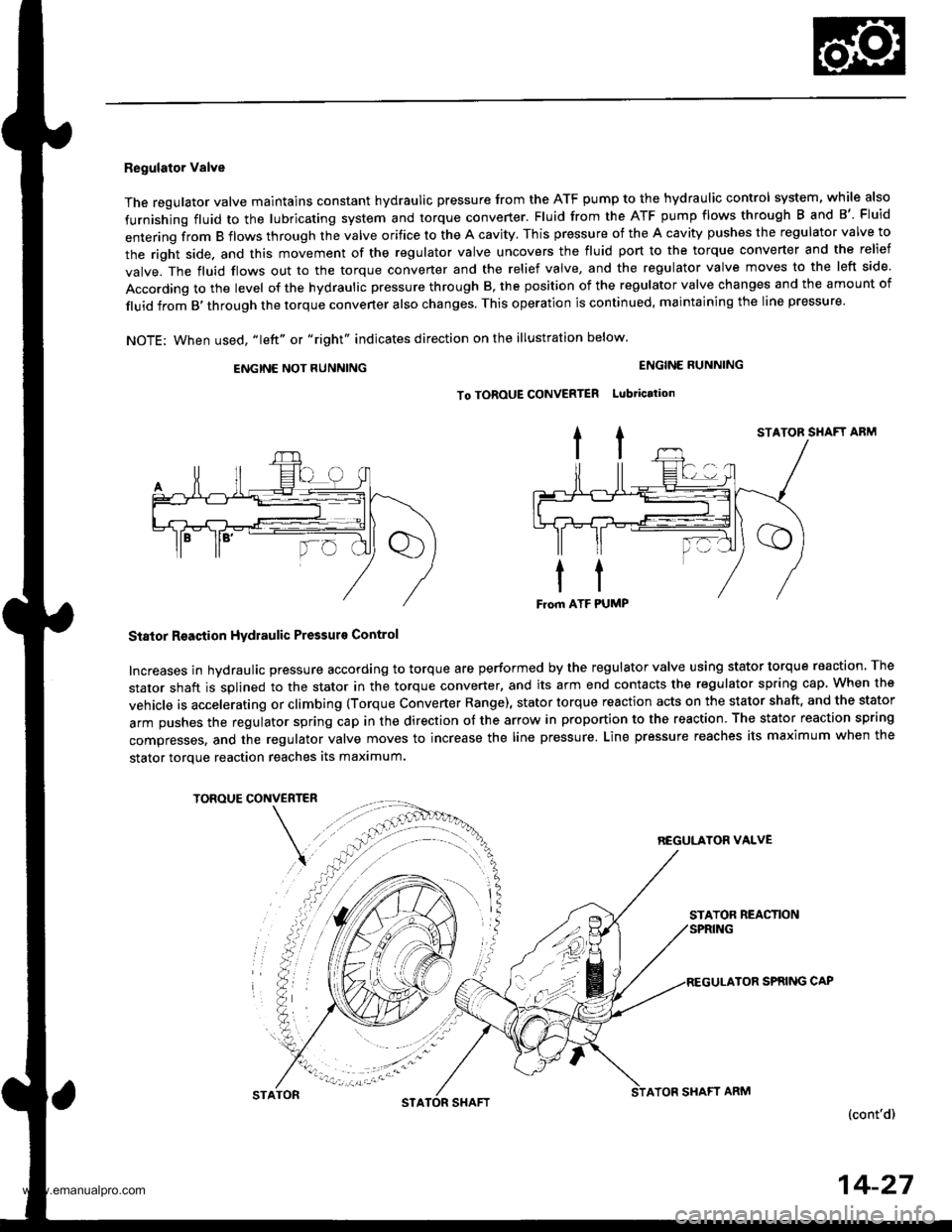
The regulator valve maintains constant hydraulic pressure from the ATF pump to the hydraullc control system, while also
furnishing fluid to the lubricating system and torque converter. Fluid from the ATF pump flows through B and B'. Fluid
entering from B flows through the valve orifice to the A cavity. This pressure of the A cavity pushes the regulator valve to
the right side. and this movement of the regulator valve uncovers the fluid port to the torque converter and the relief
valve. The fluid flows out to the torque converter and the relief valve, and the regulator valve moves to the left side.
According to the level of the hydraulic pressure through B, the position of the regulator valve changes and the amount of
fluid from B,through the torque converter also changes. This operation is continued, maintaining the line pressure.
NOTE; When used, "|eft" or "right" indicates direction on the illustration below.
ENGINE NOT RUNNING
STATOR SHAFT ABM
Stator Reaction Hydraulic Pressurs Control
Increases in hydraulic pressure according to torque are performed by the regulator valve using stator torque reaction. The
stator shaft is splined to the stator in the torque converter, and its arm end contacts the regulator spring cap When the
vehicle is accelerating or climbing (Torque Converter Range), stator torque reaction acts on the stator shaft, and the stator
arm pushes the regulator spring cap in the direction of the arrow in proportion to the reaction. The stator reaction spring
compresses, and the regulator valve moves to increase the line pressure. Line pressure reaches its maximum when the
stator torque reaction reaches its maximum.
TOROUE CONVERTER
REGULATON VALVE
STATOR REACTION
TOR SPRING CAP
(cont'd)
ENGINE RUNNING
To TOROUE CONVERTER Lubtication
STATONSTASHAFTATOF SHAFT ARM
14-27
www.emanualpro.com
Page 544 of 1395
Description
Hydraulic Control (cont'd)
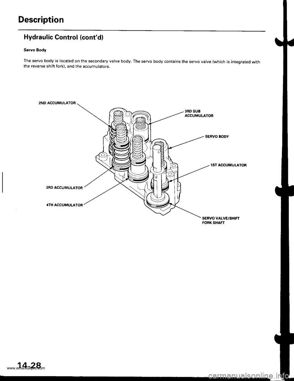
Servo Body
The servo body is located on the secondary valve body. The servo body contains the servo valve (which is integrated withthe reverse shift fork), and the accumulators.
2ND ACCUMULATOR
3RD SUBACCUMULATOR
SERVO BODY
1ST ACCUMULATOR
SERVO VALVE/SHIFTFORK SHAFT
14-28
www.emanualpro.com
Page 545 of 1395
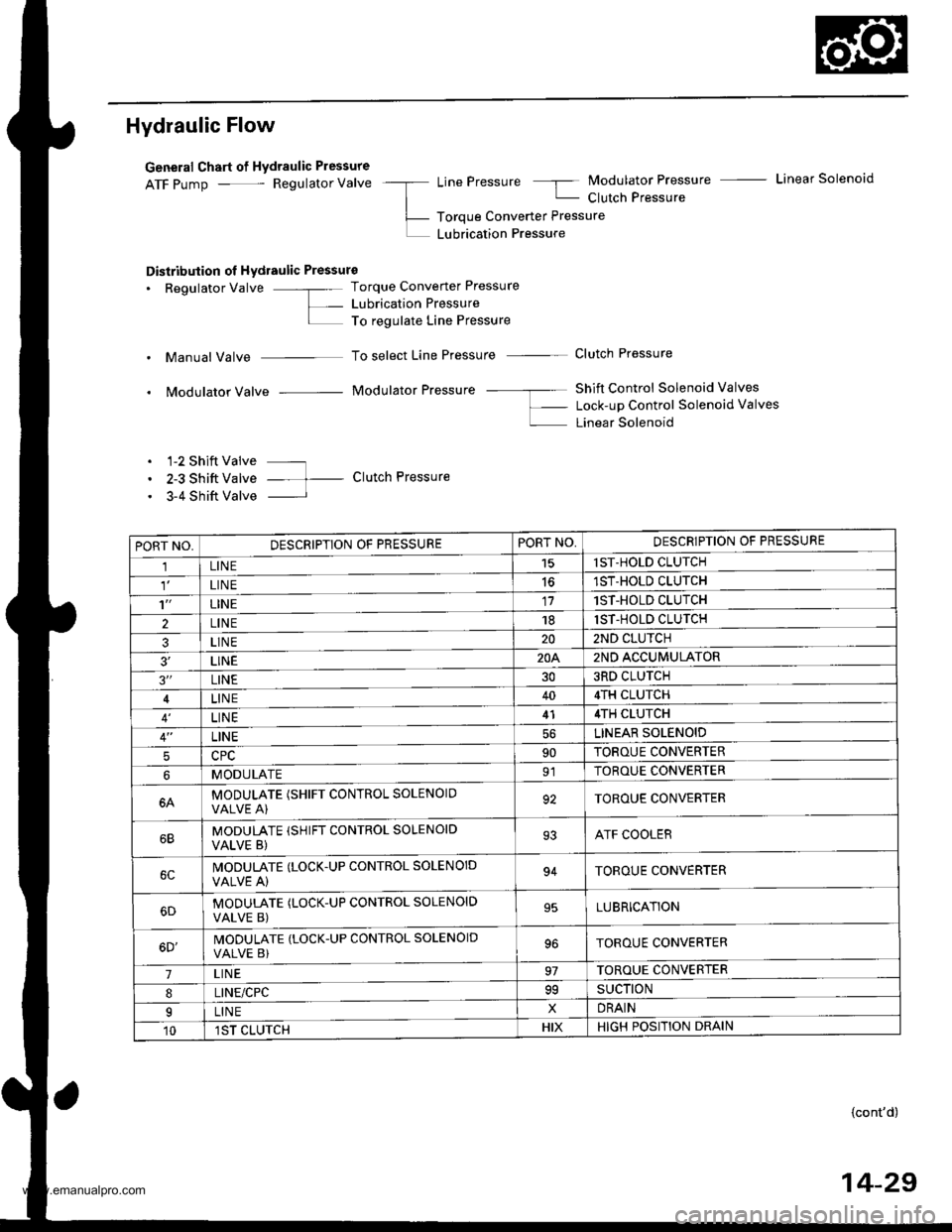
Hydraulic Flow
General Chart of Hydraulic Pressure
ATF pump - Regulator Valve -a LinePressure 5 Modulator Pressure - Linear Solenoid
| - Clutch Pressure
L- Toroue Converter Pressure
L LUbrication Pressure
Distribution ol Hydraulic Pressure
. Regulator Valve -"- Torque Converter Pressure
L- Lubrication PressureI To regulate Line Pressure
. Manual Valve To select Line Pressure - Clutch Pressure
. Modulator Valve Modulator Pressure -- ---- Shift Control Solenoid Valves
f- Lock-up Control Solenoid valves
L Linear Solenoid
. 1-2 Shift Valve ---
. 2-3 Shift Valve -- t- Clutch Pressure
. 3-4 Shift Valve I
PORT NO,DESCRIPTION OF PRESSUREPORT NO,DESCRIPTION OF PRESSURE
1LINE15lST-HOLD CLUTCH
LIN E1ST-HOLD CLUTCH
't'LINE171ST-HOLD CLUTCH
2LINE181ST-HOLD CLUTCH
3LINE202ND CLUTCH
3'�LINE20A2ND ACCUMULATOR
3"LINE303RD CLUTCH
LINE404TH CLUTCH
LINE414TH CLUTCH
LINELINEAR SOLENOID
590TOROUE CONVERTER
MODULATE91TOROUE CONVERTER
6AMODULATE (SHIFT CONTROL SOLENOIOVALVE A)92TOROUE CONVERTER
MODULATE (SHIFT CONTROL SOLENOID
VALVE B)93ATF COOLER
IVODULATE (LOCK.UP CONTROL SOLENOID
VALVE A)94TOROUE CONVERTER
MODUTATE (LOCK-UP CONTROL SOLENOID
VALVE B)95LUBRICATION
6D'MODULATE (LOCK-UP CONTROL SOLENOID
VALVE B)TOROUE CONVERTER
7LIN E97TOROUE CONVERTER
8LINE/CPC99SUCTION
ILINExDRAIN
101ST CLUTCHHIXHIGH POSITION DRAIN
{cont'd)
14-29
www.emanualpro.com
Page 546 of 1395
Description
Hydraulic Flow (cont'dl
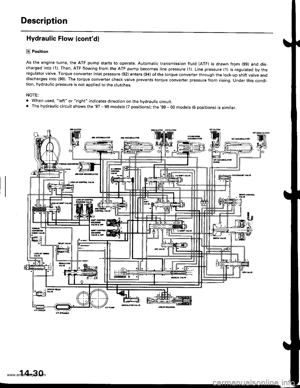
lll Position
As the engine turns, the ATF pump starts to operate. Automatic transmission fluid (ATF) is drawn from (99) and dis-charged into (1). Then, ATF flowing from the ATF pump becomes line pressure ('l). Line pressure (1) js regulated by theregulator valve. Torque converter inlet pressure {92) enters (94) of the torque conveTter through the lock-up shift valve anddischarges into (90) The torque converter check valve prevents torque converter pressure from rising. Under this condi-tion, hydraulic pressure is not applied to the clutches.
NOTE;
. When used. "|eft" o. "right" indicates direction on the hvdraulic circutt.. The hydraulic circuit shows the '97 - 98 models {7 positions}; the '99 - 00 models (6 positions) is similar.
'lF'.j.l
14-30
www.emanualpro.com
Page 547 of 1395
B Position
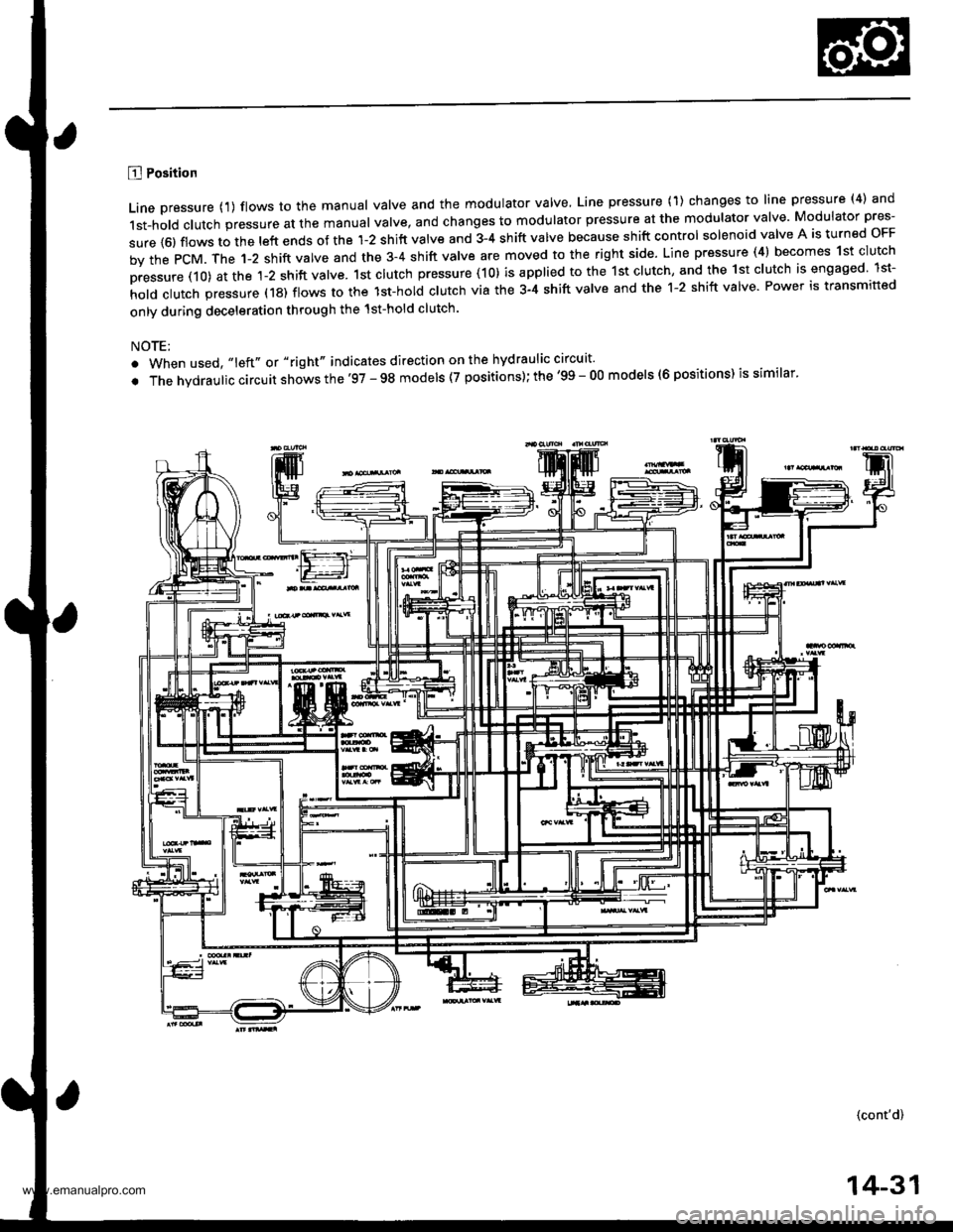
Line pressure {1) flows to the manual valve and the modulator valve, Line pressure (1) changes to line pressure (4) and
1st-hold clutch pressure at the manual valve, and changes to modulator pressure at the modulator valve Modulator pres-
sure {6) flows to the left ends of the 1-2 shift valve and 3-4 shift valve because shift control solenoid valve A is turned oFF
by the PcM. The 1-2 shift valve and the 3-4 shift valve are moved to the right side. Line pressure (4) becomes 1st clutch
pressure (10) at the 1-2 shift valve. 1st clutch pressure (10) is applied to the 1st clutch, and the 1st clutch is engaged lst-
hold clutch pressure (18) flows to the lst-hol; clutch via the 3-4 shift valve and the 1-2 shift valve Power is transmitted
only during deceleration through the 1st-hold clutch.
NOTE:
. When used, "left" or "right" indicates direction on the hydraulic circuit'
. The hvdraulic circuit shows the'97 - 98 models (7 positions); the '99 - O0 models (6 positions) is similar'
(cont'd)
14-31
www.emanualpro.com
Page 548 of 1395
Description
Hydraulic Flow (cont'dl
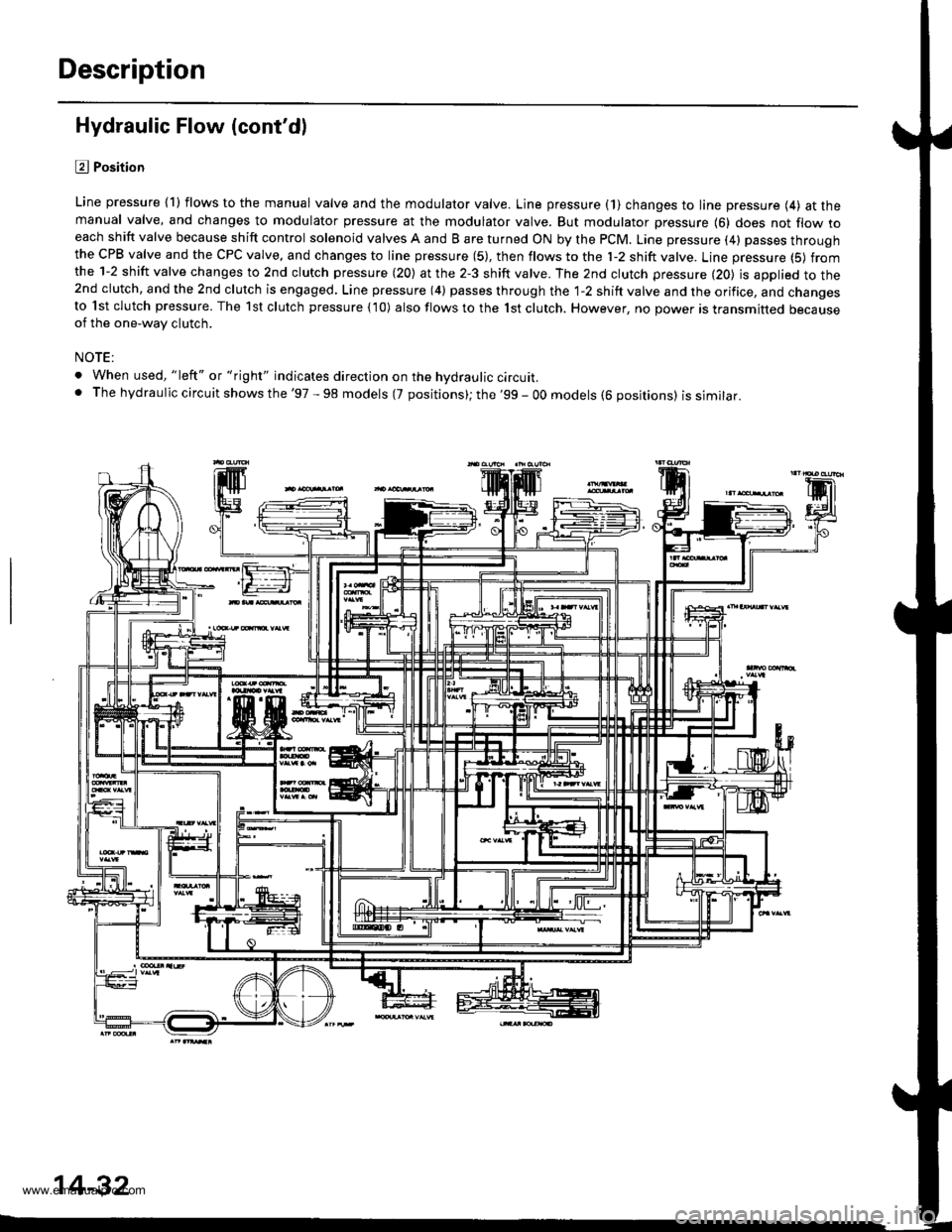
l?J Position
Line pressure {1) flows to the manual valve and the modulator valve. Line pressure (1} changes to line pressure (4) at themanual valve, and changes to modulator pressure at the modulator valve. But modulator pressure {6} does not flow toeach shift valve because shift control solenoid valves A and B are turned ON by the PCM. Line pressure (4) passes throughthe CPB valve and the CPC valve, and changes to line pressure (5), then flows to the 'l-2 shift valve. Line pressure (5) fromthe 1-2 shift valve changes to 2nd clutch pressure (20) at the 2-3 shift valve. The 2nd clutch pressure (20) is applied to the2nd clutch, and the 2nd clutch is engaged, Line pressure (4) passes through the 1-2 shift valve and the orifice, and changesto lst clutch pressure. The 1st clutch pressure {10) also flows to the 1st clutch. However, no power is transmitted becauseof the one-way clutch.
NOTE:
. When used, "left" or "right" indicates direction on the hvdraulic circuit.. The hydraulic circuit shows the '97 - 98 models (7 positions); the '99 - OO models (6 positions) issimilar.
14-32
www.emanualpro.com
Page 549 of 1395
![HONDA CR-V 1999 RD1-RD3 / 1.G Workshop Manual
E] or E Position (97 - 98 Models), and D Position (99 - 00 Modelsl
1. lst Gear
Fluid flow through the torque converter circuit is the same as in E] position. Line pressure flows to the manual valve HONDA CR-V 1999 RD1-RD3 / 1.G Workshop Manual
E] or E Position (97 - 98 Models), and D Position (99 - 00 Modelsl
1. lst Gear
Fluid flow through the torque converter circuit is the same as in E] position. Line pressure flows to the manual valve](/img/13/5778/w960_5778-548.png)
E] or E Position ('97 - 98 Models), and D Position ('99 - 00 Modelsl
1. lst Gear
Fluid flow through the torque converter circuit is the same as in E] position. Line pressure flows to the manual valve
and the modulator valve. Line pressure changes to modulator pressure (6) at the modulator valve and to line pressure
{4) at the manual valve. Modulator pressure (6) flows to the left end of the 1-2 shift valve and the 3-4 shift valve
because shift control solenoid valve A is turned oFF and B is turned oN by the PcM. The 1-2 shift valve is moved to
the right side. Line pressure {4) changes to 'lst clutch pressure (10} at the 1-2 shift valve and the orifice The 1st clutch
pressure (10) is applied to the 1st clutch and the 1st accumulator; the vehicle will move as the engine power is trans-
mitted.
NOTE:
. When used, "left" or "right" indicates direction on the hydraulic circuit.
. The hvd rau lic circuit shows th e '97 - 98 models (7 positions); the '99 - 00 models {6 positions) issimilar.
(cont'dl
14-33
www.emanualpro.com
Page 550 of 1395
Description
Hydraulic Flow (cont'dl
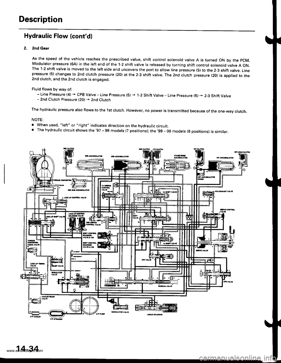
2nd Gsar
As the speed of the vehicle reaches the prescribed value. shift control solenoid valve A is turned ON by the pCM.Modulator pressure (6A) in the left end of the 1-2 shift valve is released by turning shift control solenoid valve A ON.The 1-2 shift valve is moved to the left side and uncovers the port to allow line pressure (5) to the 2-3 shift vatve. Linepressure (5) changes to 2nd clutch pressure (20) at the 2-3 shift valve, The 2nd clutch pressure {20) is appli€d to the2nd clutch. and the 2nd clutch is engaged.
Fluid flows by way of:- Line Pressure (4) + CPB Valve - Line Pressure (5) * 1-2 Shift Valve - Line pressure (S) * 2-3 Shift Valve- 2nd Clutch Pressure (20) - 2nd Clutch
The hydraulic pressure also flows to the lst clutch. However, no power is transmitted because of the one-wav ctutch.
NOTE:
. When used, "|eft" or "right" indicates direction on the hydraulic circurr_' The hydraulic circuit shows the'97 - 98 models (7 positions); the '99 - 00 models (6 positions) is similar,
14-34
www.emanualpro.com