Pin HONDA CR-V 1999 RD1-RD3 / 1.G Repair Manual
[x] Cancel search | Manufacturer: HONDA, Model Year: 1999, Model line: CR-V, Model: HONDA CR-V 1999 RD1-RD3 / 1.GPages: 1395, PDF Size: 35.62 MB
Page 445 of 1395
Transfer Assembly
lnstallation
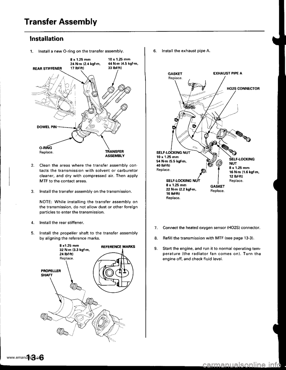
1. Install a new O-ring on the transfer assembly.
8 x 1.25 mm24 N.m (2.4 kgt m,17 rbt.ftl
10 x 1.25 mm44 N.m (4.5 kgJ.m,
2.
DOWEL PIN
Replace.TRANSFEBASSEMBLY
Clean the areas where the transfer assembly con
tacts the transmission with solvent or carburetor
cleaner, and dry with compressed air. Then apply
MTF to the contact areas.
Installthe transfer assembly on the transmission.
NOTE: While installing the transfer assembly on
the transmission, do not allow dust or other foreign
particles to enter the transmission.
lnstall the rear stiffener.
Install the propeller shaft to the transfer assembly
by aligning the reference marks,
8 x1.25 mm32 N.m 13.3 kg{.m,24 tbf.ftl
REFERENCE MARKS
6. Install the exhaust pipe A,
GASKETEXHAUST PIPE A
HO2S CONNECTOR
10 x 1 .25 mm54 N.m (5.5 kgt m,40 tbtfttReplace.
SELF.LOCKING
NUT8 x 1.25 mm16 N.m {1.6 kgf.m,12 tbt.ft)Replace.8 x 1.25 mmzzN.m l2.2kg!-m,16 rbf.trtReplace.
7.Connect the heated oxygen sensor (HO2S) connector.
Relill the transmission with MTF (see page 13-3).
Start the engine, and run it to normal operating tem-
perature (the radiator tan comes on). Turn the
engine off. and check fluid level.
8.
9.
www.emanualpro.com
Page 447 of 1395
Transmission Assembly
Removal (cont'dl
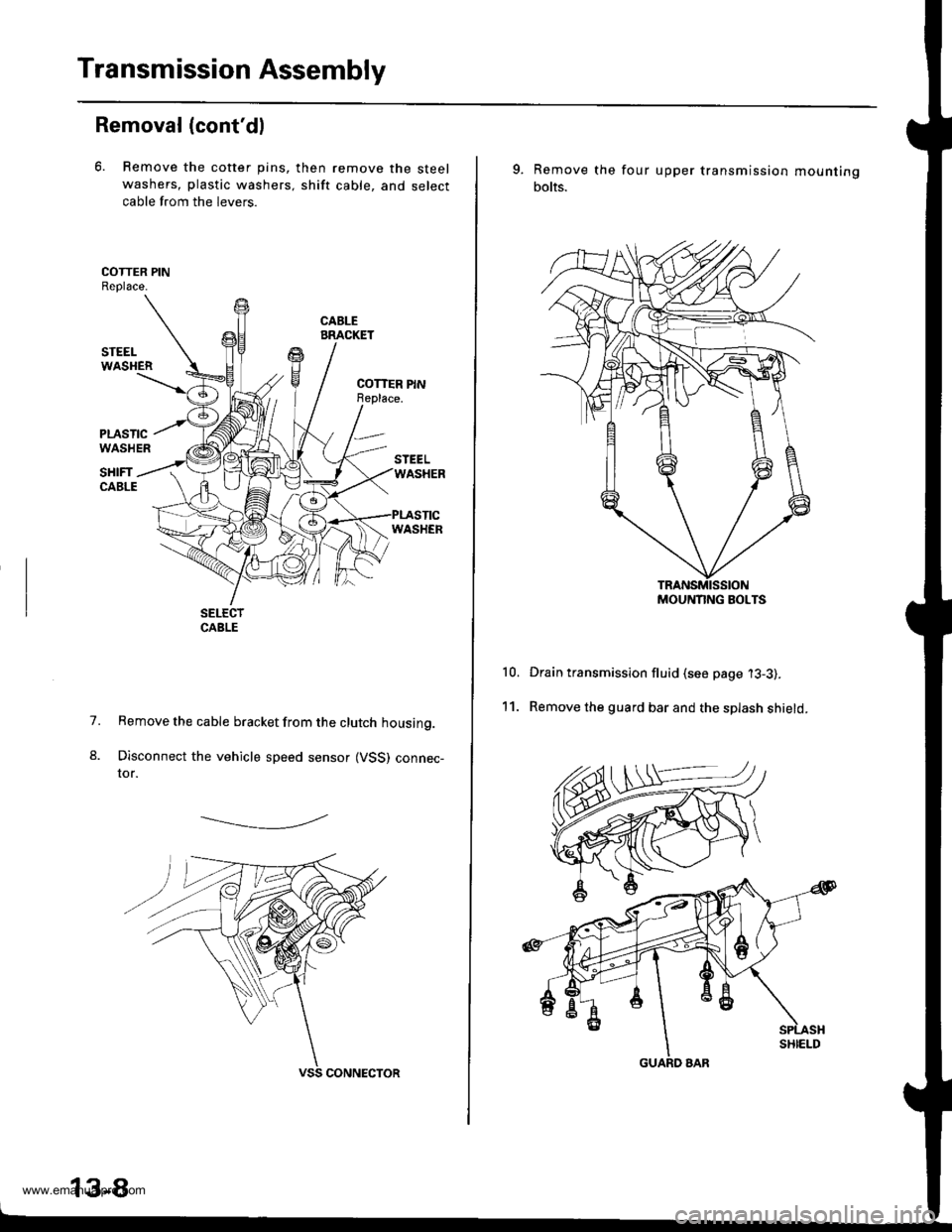
6. Remove the cotter pins,
washers, plastic washers.
cable from the levers.
then remove the steel
shift cable, and select
1.
8.
Remove the cable bracket from the clutch housing.
Disconnect the vehicle speed sensor (VSS) connec-tor.
-------------.2
13-8
9. Remove the
bolts.
four upper transmission mou nting
10.
11.
Drain transmission fluid (see page '13-3).
Remove the guard bar and the splash shield.
MOUNNNG BOLTS
www.emanualpro.com
Page 448 of 1395
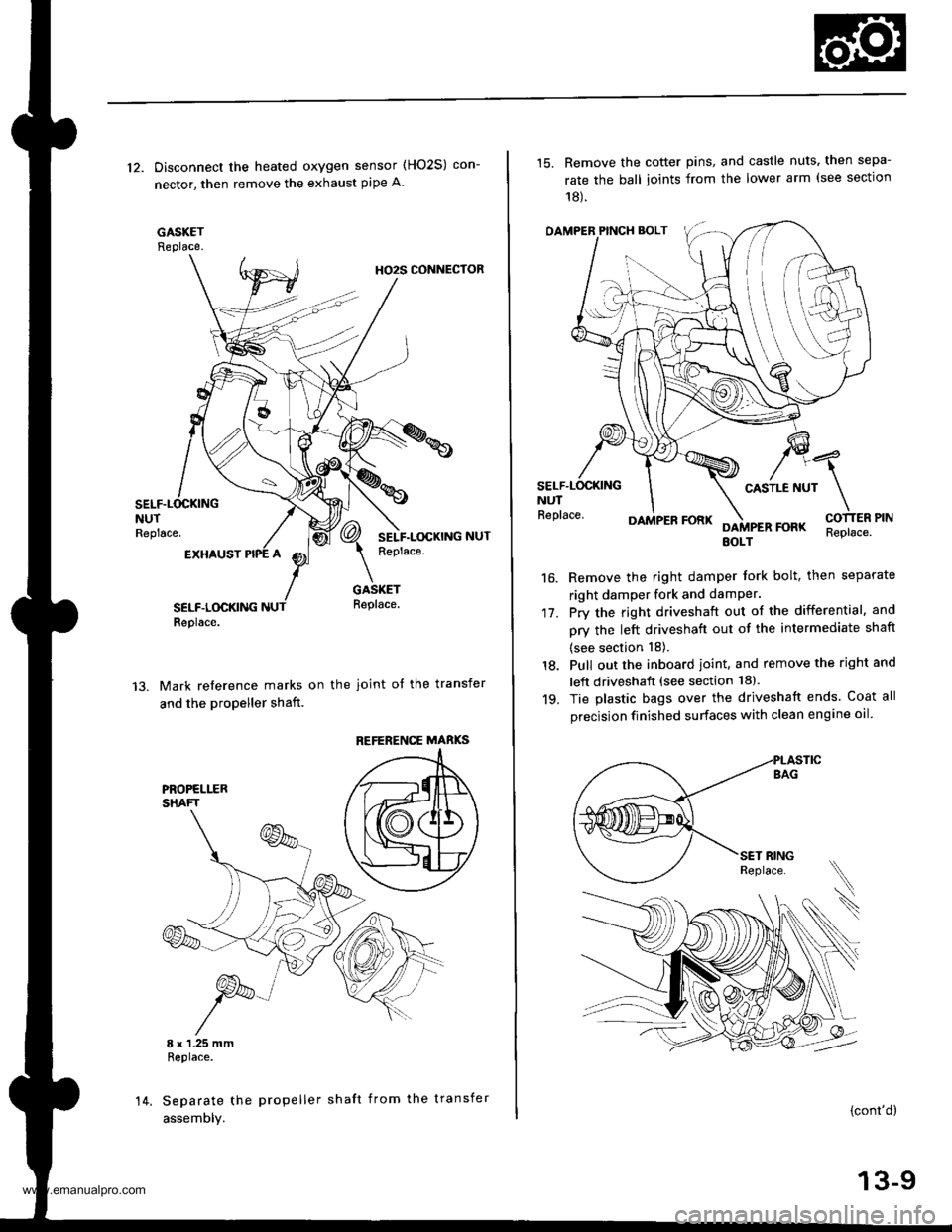
12. Disconnect the heated oxygen sensor (HO2S) con-
nector, then remove the exhaust pipe A.
GASKETReplace.
HO2S CONNECTOR
NUTReplace.
EXHAUST
SELF.LOCKINGReplace.
GASKETReplace.
Mark reference marks on the joint of the transfer
and the propeller shaft.
8 x 1.25 mmReplace.
Separate the propeller shaft from the transfer
assemDly.
REFERENCE MABKS
14.
15. Remove the cotter pins, and castle nuts. then sepa-
rate the ball ioints from the lower arm (see sectlon
18).
OAMPER PINCH BOLT
CASTLE NUTNUTReplace.
17.
16.
DAMPER FORKFOFKEOLTReplace.
Remove the right damper tork bolt, then separate
right damper fork and damPer.
Pry the right driveshaft out of the differential, and
pry the left driveshaft out of the intermediate shaft
(see section 18).
Pull out the inboard ioint, and remove the right and
left driveshaft (see section 18).
Tie plastic bags over the driveshatt ends. Coat all
precision finished surfaces with clean engine oil
18.
19.
\
{cont'd}
13-9
www.emanualpro.com
Page 452 of 1395
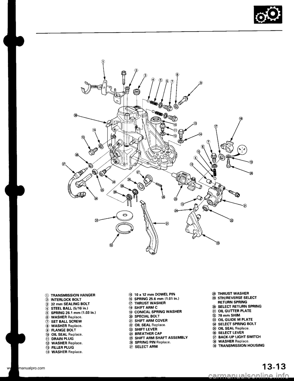
C) TRANSMISSION HANGER
O INTERLOCK BOLT
O 32 mm SEALING BOLT
@ STEEL BALL {5/16 in.)
€) SPRING 26.1 mm {1.03 in.l
@ wasHER Replace.
O sET BALL scREw
@ WASHER Replace.
€) FLANGE BOLT
@ oll SEAL Replace.
@ DRAIN PLUG
@ WASHER Replace.
@ FILLER PLUG
@ WASHER Replace.
(9 10 x 12 mm DOWEL PIN(D SPRING 25.6 mm 11.01 in.l
€' THRUST WASHER
@} SHIFT ARM C(3 CONICAL SPRING WASHER
@ SPECTAL BOLT
8] SHIFT ARM COVER
@ OIL SEAL Replace.
€! SHIFT LEVER
@I BREATHER CAP(2! SHIFT ARM SHAFT ASSEMBLY
@ SPRING PIN Replace.O SELECT ARM
€!} THRUST WASHER
@ sTH/REVERSE SELECTRETURN SPRING
@ SELECT RETURN SPRING
€) OIL GUTTER PLATE
@ 78 mm SHIM
@ OIL GUIOE M PLATE
@ SELECT SPRING BOLT
@ OIL SEAL Replace.
@ SELECT LEVER
O BACK.UP LIGHT SWITCH
@ WASHER Replace.OO TRANSMISSION HOUSING
13-13
www.emanualpro.com
Page 454 of 1395
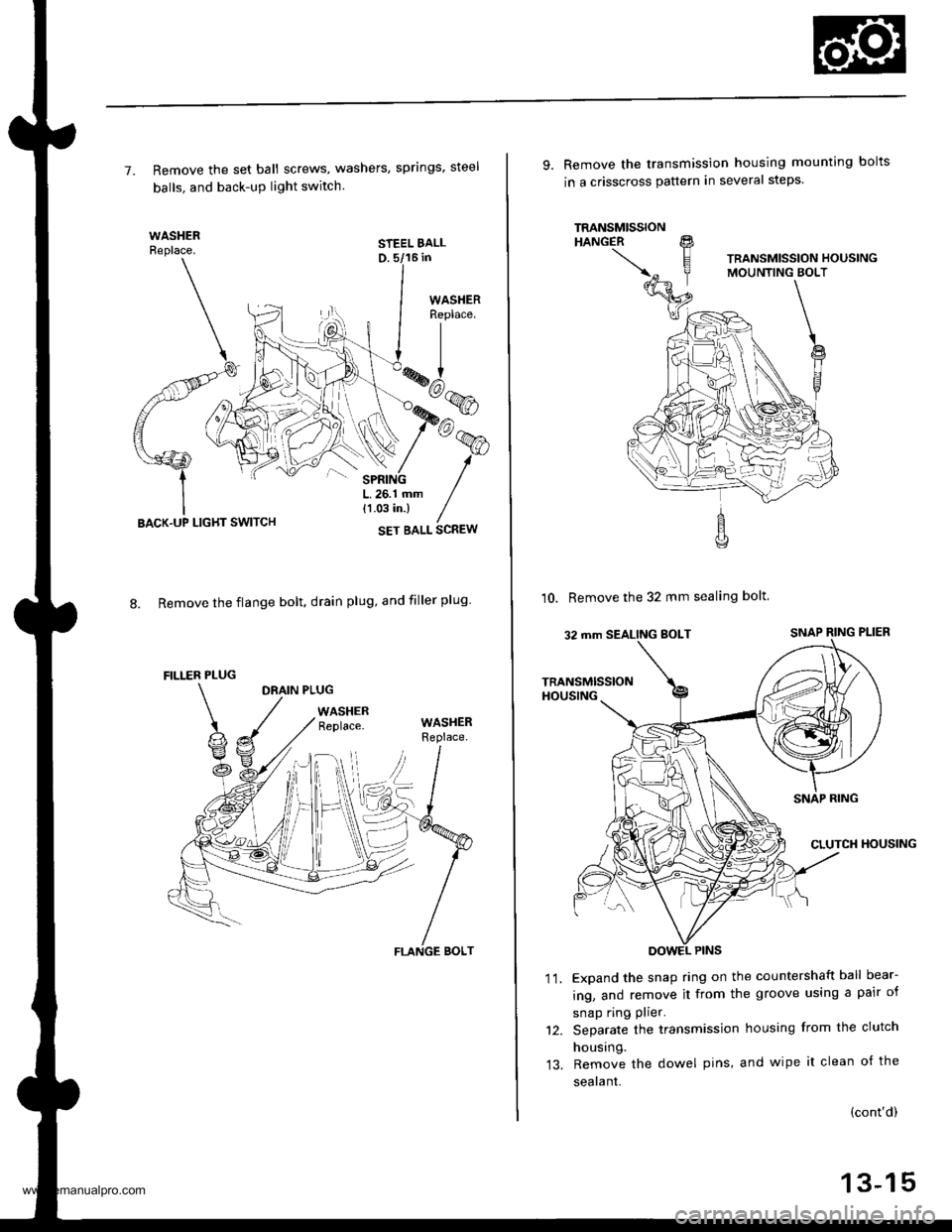
7. Remove the set ball screws, washers, springs, steel
balls. and back-uP light switch.
STEEL BALLD. 5/16 in
8. Remove the flange bolt. drain plug, and filler plug
DRAIN PLUG
WASHERReplace.
LIGHT SWITCH
FILLER PLUG
WASHERReplace.
FLANGE BOLT
9. Remove the transmission housing mounting bolts
in a crisscross pauern in several steps.
10. Remove the 32 mm sealing bolt
Expand the snap ring on the countershaft ball bear-
ing, and remove it from the groove using a pair of
snap ring plier.
Separate the transmission housing from the clutch
housing.
Remove the dowel pins, and wipe it clean of the
sealant.
'I t.
(cont'd)
13-15
www.emanualpro.com
Page 455 of 1395
Transmission Assembly
Disassembly (cont'dl
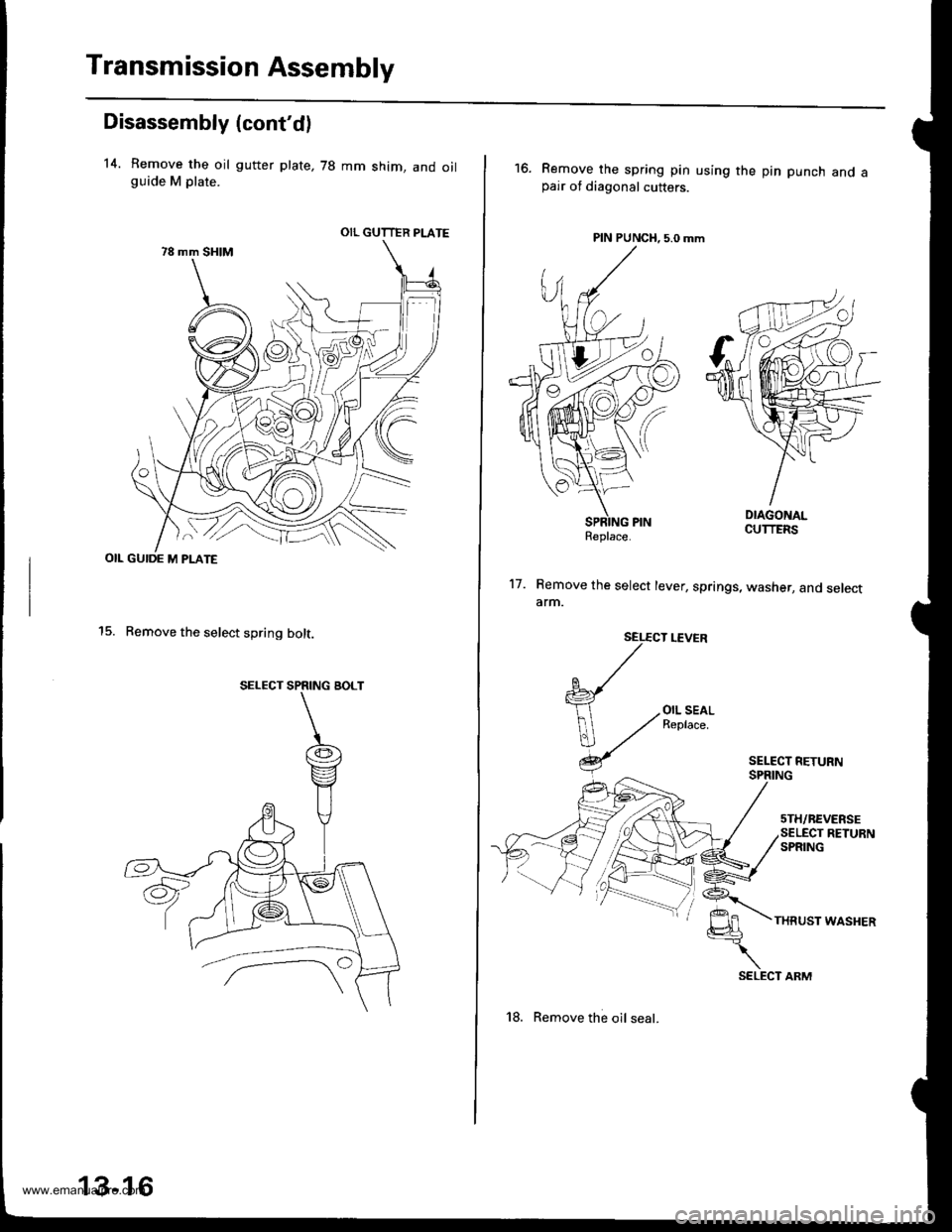
14. Remove the oil gutter plate, 78 mm shim, and oilguide M plate.
OIL GUIDE M PLATE
15. Remove the select spring bolt.
OIL GUTTER PLATE
SELECT SPRING BOLT
13-16
18. Remove the oil seal.
16.Remove the spring pin using the pin punch and apair of diagonal cutters.
PIN PUNCH, 5.0 mm
17. Remove the select lever, springs, washer, and selectarm.
SEL€CT LEVER
{
V
OIL SEALReplace.
THRUST WASHER
Replace.
SELECT ARM
www.emanualpro.com
Page 458 of 1395
2.
Clearance InsPection
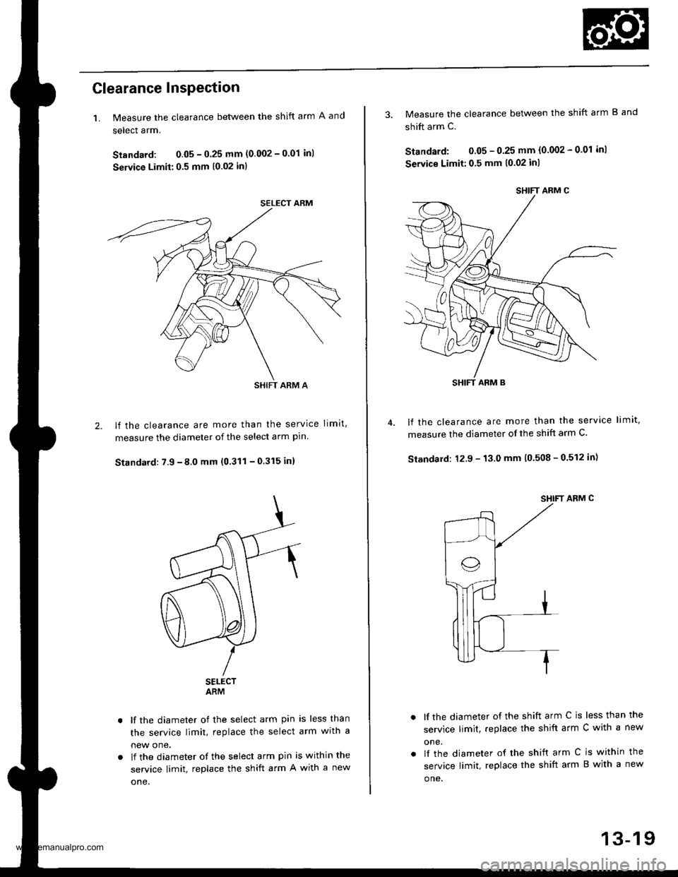
1. Measure the clearance between the shift arm A and
select arm.
Standard: 0.05 - 0 25 mm (0.002 - 0'01 inl
Service Limit:0.5 mm (0.02 in)
lf the clearance are more than the service limit,
measure the diameter of the select arm pln
Standard: 7.9 - 8.0 mm (0.311 - 0.315 in)
SELECTARM
lf the diameter of the select arm pin is less than
the service limit, replace the select arm wrtn a
new one.
lf the diameter of the select arm pin is within the
service limit, replace the shift arm A with a new
one.
SELECT ARM
SHIFT ARM A
SHIFT ARM C
SHIFT ARM B
3. Measure the clearance between the shift arm B and
shift arm c.
Standard: 0.05 - 0.25 mm (0.002 - 0.01 inl
Seryice Limit:0,5 mm (0.02 inl
lf the clearance are more than the service limit,
measure the diameter of the shift arm C.
Standard: 12.9 - 13.0 mm (0 508 - 0.512 in)
SHIFT ARM C
lf the diameter of the shift arm C is less than the
service limit, replace the shift arm C with a new
one.
lf the diameter of rhe shift arm C is within the
service limit, replace the shift arm B with a new
o ne.
13-19
www.emanualpro.com
Page 459 of 1395
Reverse Shift Holder
Clearance Inspection
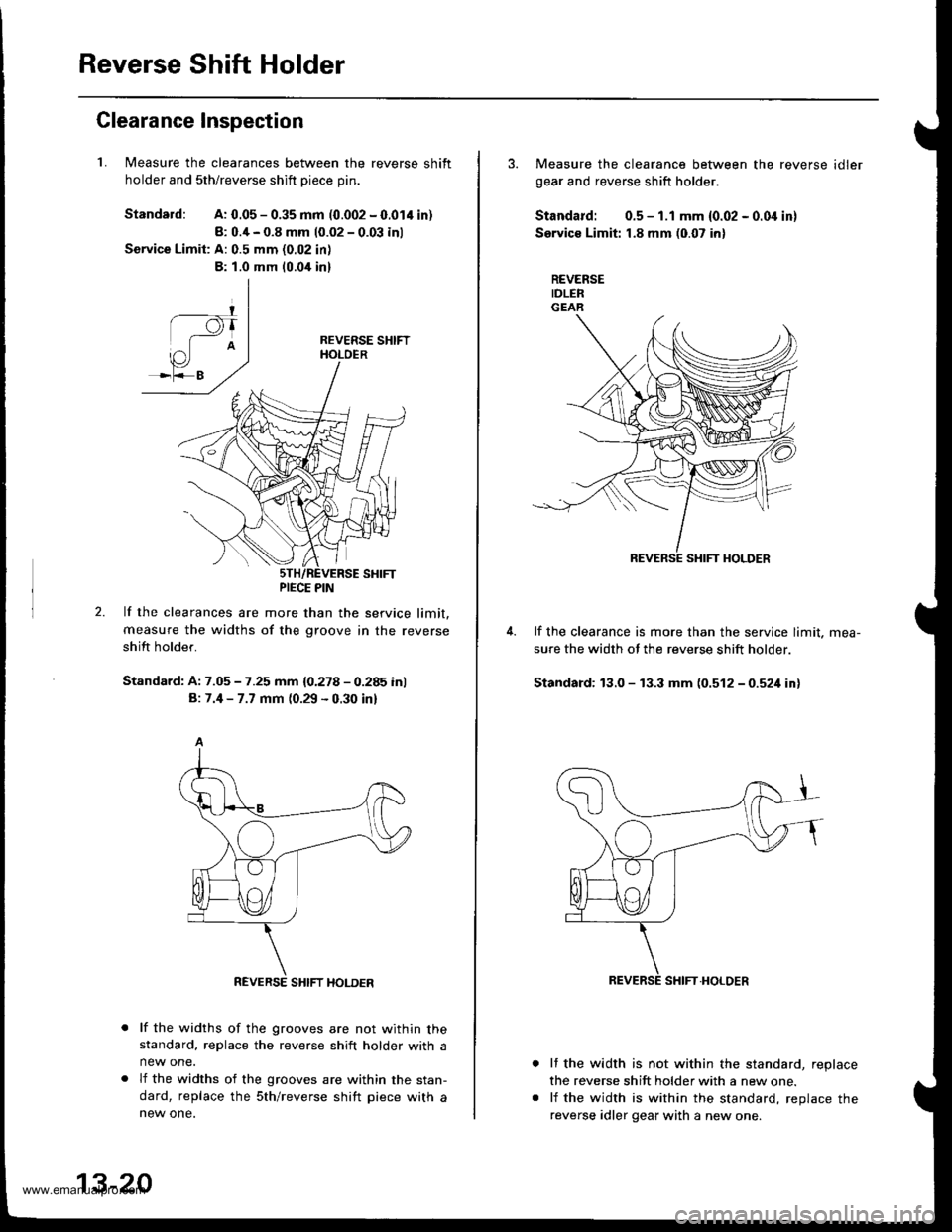
1.Measure the clearances between the reverse shift
holder and sth/reverse shift Diece Din.
Standard:A: 0.05 - 0.35 mm (0.002 - 0.014 in)
8: 0.4 - 0.8 mm 10.02 - 0.03 inl
Service Limit: A: 0.5 mm (0.02 in)
B: 1.0 mm 10.0,[ in]
2.lf the clearances are more than the service limit.
measure the widths of the groove in the reverse
shift holder.
Standard: A: 7.05 - 7.25 mm {0.278 - 0.285 inl
B: 7.4 - 7.7 mm (0.29 - 0.30 inl
lf the widths of the grooves are not within thestandard, replace the reverse shift holder with a
new one.
lf the widths of the grooves are within the stan-
dard, replace the sth/reverse shift piece with anew one.
PIECE PIN
REVERSE SHIFT HOLDER
13-20
3. Measure the clearance between the reverse idler
gear and reverse shift holder.
Standard: 0.5 - 1.1 mm {0.02 - 0.0i1 in}
Service Limit: 1.8 mm (0.07 in)
REVERSEIDLERGEAR
lf the clearance is more than the service limit. mea-
sure the width ot the reverse shift holder.
Standard: 13.0 - 13.3 mm (0.512-0521inl
It the width is not within the standard, replace
the reverse shift holder with a new one.
lf the width is within the standard, reolace the
reverse idler gear with a new one.
www.emanualpro.com
Page 460 of 1395
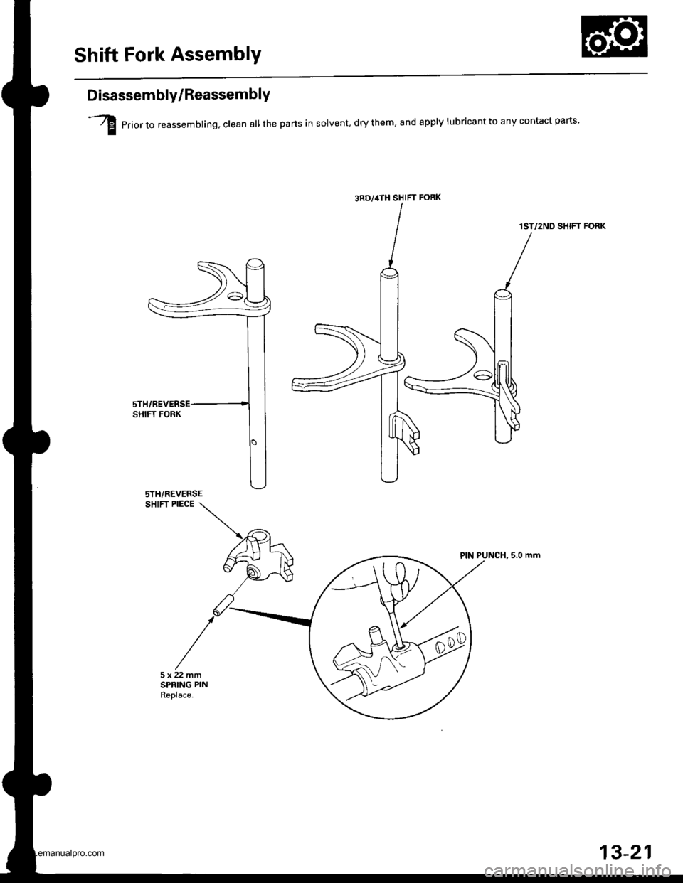
Shift Fork Assembly
Disassembly/ReassemblY
I erior,o reassembling, clean all the pans in solvent, dry them, and apply lubricant to any contact parts
1ST/2ND SHIFT FORK
SHIFT PIECE
PIN PUNCH, 5.0 mm
3RD/,|TH SHIFT FoRK
5TH/REVERSE
13-21
www.emanualpro.com
Page 477 of 1395
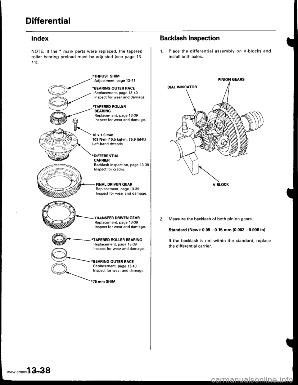
Differential
lndex
NOTE: lf the * mark parts were replaced, the tapered
roller bearing preload must be adjusted (see page 13-
41).
*THRUST SHIMAdiustment, Page 13'41
+BEARING OUTER RACEBeplacement, page 13 40Inspect for wear and damage.
*TAPERED ROLLERBEARINGReplacement, page l3-39Inspect for wear and damage.
10 x 1.0 mm103 N.m {10.5 kgf m, 75.9 lbf.ft}Left-hand threads
CARRIERBacklash inspection, page 13 38lnspect for cracks.
FINAL DRIVEN GEARReplacement, page 13-39Inspect for wear and damage
TRANSFER DRIVEN GEARReplacement, page 13-39Inspect {or wear and damage.
,,4\
W-
*TAPERED ROLLER BEARINGBeplacement, page 13'39Inspect for wear and damage.
IEEARING OUTER RACEReplacement, page 13-40Inspect for wear and damage.
.75 mm SHIM
13-38
Backlash Inspection
1. Place the differential
install both axles.
assembly on V-blocks and
PINION GEARS
V-BLOCK
2. Measure the backlash ot both pinion gears.
Standard (Newl: 0.05 - 0.15 mm (0.002 - 0.006 inl
lf the backlash is not within the standard, reolace
the differential carrier.
www.emanualpro.com