Pin HONDA CR-V 1999 RD1-RD3 / 1.G Owner's Guide
[x] Cancel search | Manufacturer: HONDA, Model Year: 1999, Model line: CR-V, Model: HONDA CR-V 1999 RD1-RD3 / 1.GPages: 1395, PDF Size: 35.62 MB
Page 178 of 1395
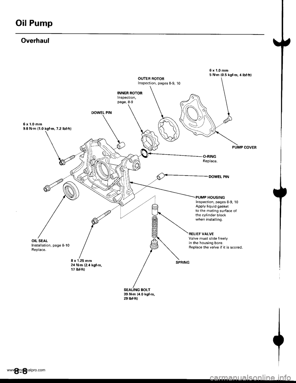
Oil Pump
Overhaul
6xl.0mm9.8 N m (1.0 kg,t m, 7.2 lbf ftl
6x1.0mm5 N.m {0.5 kgt m. 4lbtft}OUTER ROTORInspection, pages 8-9, 1O
PUMP COVER
lnspection, pages 8-9, 10Apply liquid gasketto the mating surface ofthe cylinder blockwhen anstalling.
REI-IEF VALVEValve must slide freelyin the housing bore.Replace the valve if it is scored.
8 x 1.25 mm2{ N.m (2.4 kgf m,17 tbf.fi)
DOWEL PIN
8-8
www.emanualpro.com
Page 180 of 1395
Oil Pump
13.
Removal/lnspection/lnstallation (cont'd)
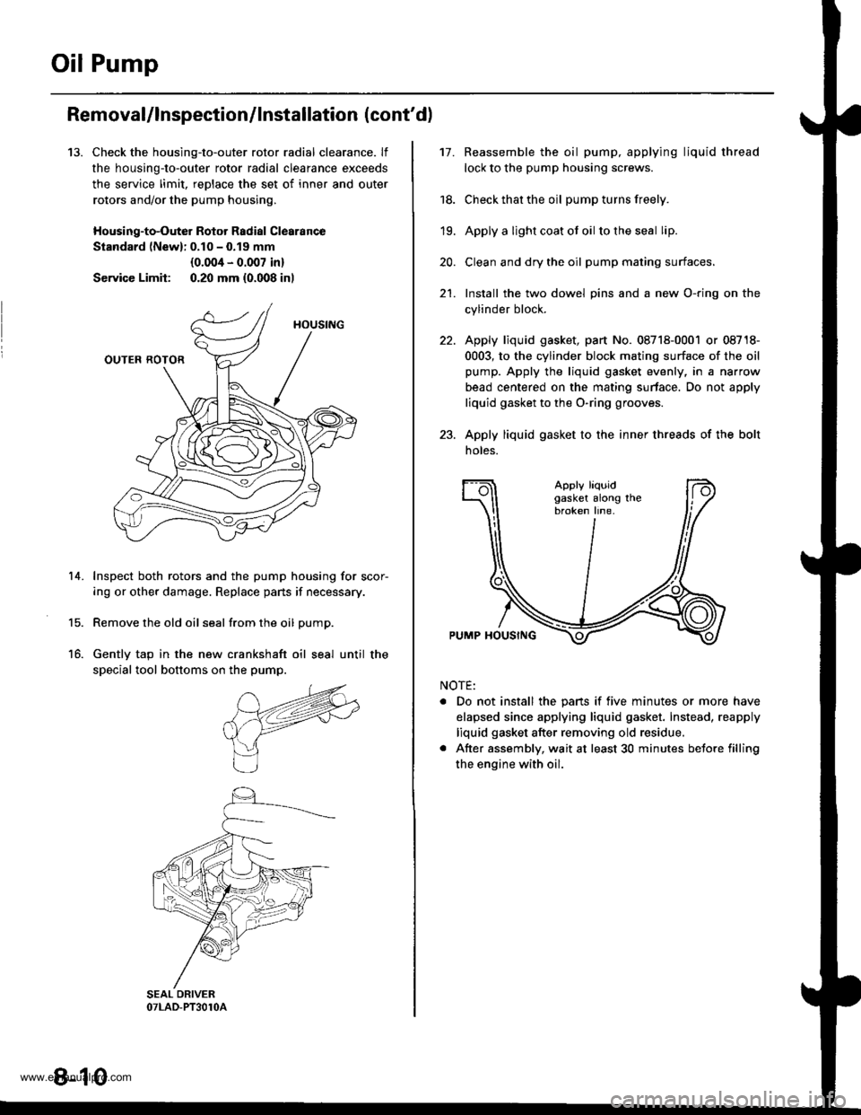
Check the housing-to-outer rotor radial clearance. lf
the housing-to-outer rotor radial clearance exceeds
the service limit, reDlace the set of inner and outer
rotors and/or the pump housing,
Housing-to-Outer Rotor Radial Clearance
Standard lNewl: 0.10 - 0.19 mm
{0.004 - 0.007 in}
Service Limit: 0.20 mm {0.008 inl
Inspect both rotors and the pump housing for scor-
ing or other damage. Replace pans if necessary.
Remove the old oil seal from the oil pump.
Gently tap in the new crankshaft oil seal until the
special tool bottoms on the pump.
14.
15.
16.
8-10
17.Reassemble the oil pump, applying liquid thread
lock to the pump housing screws.
Check that the oil pump turns freely.
Apply a light coat ot oil to the seal lip.
Clean and dry the oil pump mating surfaces.
Install the two dowel pins and a new O-ring on the
cylinder block.
Apply liquid gasket, part No. 08718-0001 or 08718-
0003, to the cylinder block mating surface of the oil
pump. Apply the liquid gasket evenly, in a narrow
bead centered on the mating surface. Do not apply
liquid gasket to the O-ring grooves.
Apply liquid gasket to the inner threads of the bolt
noles.
18.
19.
20.
21.
Apply liquidgasket along thebroken line.
PUMP HOUSING
NOTE:
. Do not install the pans if five minutes or more have
elapsed since applying liquid gasket. Instead, reapply
liquid gasket after removing old residue.
. After assembly, wait at least 30 minutes betore filling
the engine with oil.
www.emanualpro.com
Page 181 of 1395
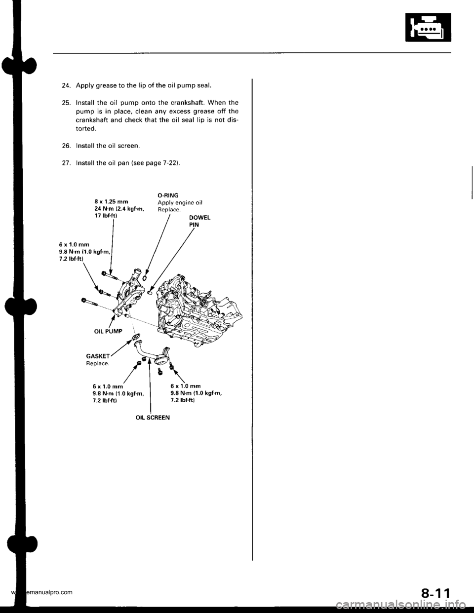
24.Apply grease to the lip of the oil pump seal.
Install the oil pump onto the crankshaft. When the
pump is in place, clean any excess grease off the
crankshaft and check that the oil seal lip is not dis-
torted.
lnstall the oil screen.
Install the oil pan {see page 7-22).2't .
8 x 1.25 mm24 N.m 12.4 kgf.m,'17 tbf.ft)
O-RINGApply engine oilReplace.
6x1.0mm9.8 N.m {1.0 kgf.m,1 .2lbfitl
DOWELPIN
6x1.0mm9.8 N.m (1.0 kgf.m.7.2 tbtftl
OIL PUMP
6x1.0mm9.8Nm(1.0kgf.m,7.2 tbt ft)
OIL SCBEEN
8-11
www.emanualpro.com
Page 196 of 1395
Thermostat
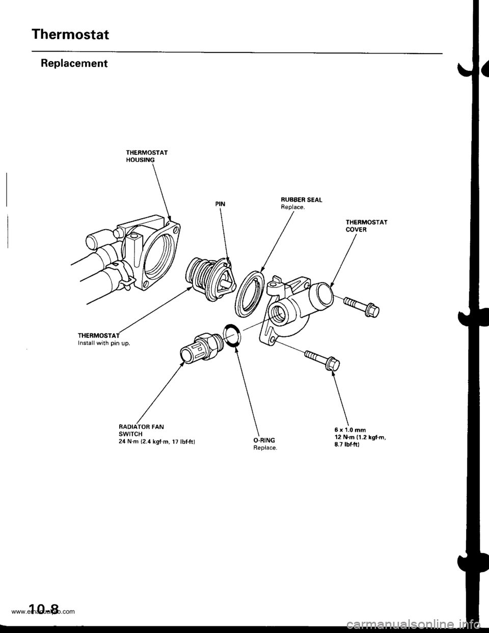
Replacement
THERMOSTAInstall with pin up.
THERMOSTATHOUSING
RUBBER SEALReplace.
RADIATOB FANswtTcH24 N.m {2.4 kgtm, l7 lbt.ftl
THERMOSTATCOVER
12 N.m (1.2 kgl.m,8.7 tbtftl
6 x '1.0 mm
10-8
www.emanualpro.com
Page 199 of 1395
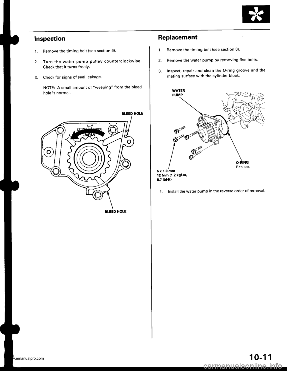
Inspection
1.
2.
Remove the timing belt (see section 6)
Turn the water pump pulley counterclockwise.
Check that it turns freely.
Check for signs of seal leakage.
NOTE: A small amount ol "weeping" from the bleed
hole is normal.
BIIED HOLE
Replacement
1. Remove the timing belt (see section 6).
2. Remove the water pump by removing five bolts
3, Inspect, repair and clean the O-ring groove and the
mating surface with the cylinder block.
Replace.6x1.0mm't2 N.m 11 2 kgf m.
8.7 tbf.ftl
4. lnstall the water pump in the reverse order of removal.
-
I
I
10-1 1
www.emanualpro.com
Page 271 of 1395
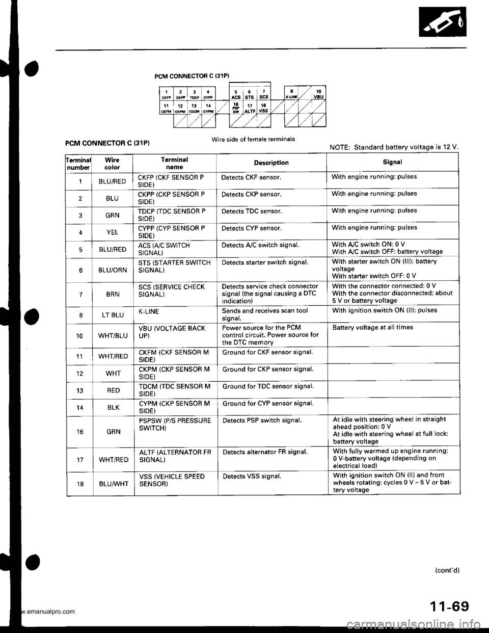
PCM CONNECTOR C (31PI
ferminalnumberWirecolorTerminalnameDoscriptionSignal
'tBLUiREDCKFP (CKF SENSOR PSIDE)Detects CKF sensor.With engine running: pulses
2BLUCKPP (CKP SENSOR PSIDE)Detects CKP sensor.With engine running: pulses
3GRNTDCP (TDC SENSOR PSIDE)Detects TDC sensor.With engine running: pulses
4YELCYPP (CYP SENSOR PSIDE)Detects cYP sensor.With engine running: pulses
5BLU,frEDACS (A/C SWTTCHSIGNAL)Detects A,/C switch signal.With AJC switch ON: 0 VWith A,/C switch OFF: battery voltage
BLU/ORNSTS (STARTER SWITCHSIGNAL)
Detects starter switch signal.With starter switch ON (lll): bafteryvoltageWith staner switch OFF: 0 V
7BRNSCS (SERVICE CHECKSIGNAL)
Detects service check connectorsignal (the signal causing a DTCindication)
With the connector connected: 0 V
With the connector disconnected: about
5 V or battery voltage
8LT BLUK-LINESends and receives scan toolsrgnal.With ignition switch ON (ll): pulses
10WHT/BLUVBUUP)
(VOLTAGE BACKPower source tor the PCMcontrol circuit. Power source for
the DTC memory
Battery voltage at all times
11WHT/REDCKFM (CKF SENSOR MSIDE)Ground for CKF sensor signal.
12WHTCKPM (CKP SENSOR I\4SIDE)Ground lor CKP sensor signal.
13REDTDCM (TDC SENSOR MSIDE}Ground for TDC sensor signal.
14BLKCYPM (CKP SENSOR MSIDE}Ground for CYP sensor signal.
16GRN
PSPSW (P/S PRESSUREswtTcH)Detects PSP switch signal.At idle with steering wheel in straightahead position:0 VAt idle with steering wheel at full lock:
battery voltage
17WHT/REDALTF (ALTERNATOR FRSIGNAL)
Detects alternator FR signal.With fully warmed up engine running:
0 V-battery voltage {depending onelectrical load)
18BLUA/VHTVSS (VEHICLE SPEEDSENSOR)Detects VSS signal.Wirh ignition switch ON (ll) and frontwheels rotating: cycles 0 V - 5 V or bat-tery voltage
Wire side of femaie terminalsPCM CONNECTOR C {31PINOTE: Standard battery voltage is 12 V.
(cont'd)
www.emanualpro.com
Page 283 of 1395

Fuel Cut-off Control
. During deceleration with the throttle valve closed, current to the fuel injectors iscutoffto improvefuel economyat
speeds over 970 rpm ('97 - 98 models), 920 rpm ('99 - 00 modelsl.
. Fuel cut-off action also takes place when engine speed exceeds 6,500 rpm ('97 - 98 models), 6900 rpm ('99 - 00
models), regardless of the position of the throttle valve, to protect the engine from over-rewing.
With Ay'T model. the PCM cuts the fuel at engine speeds over 5,000 rpm when the vehicle is not moving.*'�
4,./C Comoressor Clutch Relav
When the ECM/PCM receives a demand for cooling from the air conditioning system, it delays the compressor from
being energized, and enriches the mixture to assure a smooth transition to the Ay'C mode.
Evaporative Emission (EVAP) Purge Control Solenoid Valve
When the engine coolant temperature is above 154"F (68'C), the ECM/PCM controls the EVAP purge control solenoid
valve which controls vacuum to the EVAP purge control canister,
Alternator Control
The system controls the voltage generated at the alternator in accordance with the electrical load and driving mode.
which reduces the engine load to improve the fuel economy.
PCM Fail-saf e/Back-up Functions
1. Fail-safe Function
When an abnormality occurs in a signal from a sensor, the ECM/PCM ignores that signal and assumes a pre-pre
grammed value for that sensor that allows the engine to continue to run.
2. Back-up Function
When an abnormality occurs in the ECM/PCM itself, the fuel injectors are controlled by a back-up circuit independent
of the system in order to permit minimal driving.
3. Self-diagnosis Function IMalfunction Indicator Lamp (MlL)l
When an abnormality occurs in a signal from a sensor, the ECM/PCM supplies ground for the MIL and stores the DTC
in erasable memory. When the ignition is initially turned on {ll), the ECM/PCM supplies ground for the MIL for two
seconds to check the MIL bulb condition.
4. Two Trio Detection Method
To prevent false indications, the Two Trip Detection Method is used for the HO2S*1, fuel metering-related. idle control
system, ECT sensor and EVAP control system self-diagnostic functions. When an abnormality occurs, the ECM/PCM
stores it in its memory. When the same abnormality recurs after the ignition switch is turned OFF and ON (ll) again,
the ECM/PCM informs the driver by lighting the MlL. However, to ease troubleshooting, this function is cancelled
when you jump the service check connector, The MIL will then blink immediately when an abnormality occurs.
5. Two (or Three) Driving Cycle Detection Method {'97 model)
A "Driving Cycle" consists of starting the engine, beginning closed loop operation, and stopping the engine. lf misfir-
ing that increases emissions or EVAP control system malfunction is detected during two consecutive driving cycles.
or TWC deterioration is detected during three consecutive driving cycles, the ECM/PCM turns the MIL on. However, to
ease troubleshooting, this function is cancelled when you jump the service check connector. The MIL will then blink
immediately when an abnormality occurs.
*1: '97 - 98 models*2: '99 - 00 models
5.
www.emanualpro.com
Page 377 of 1395
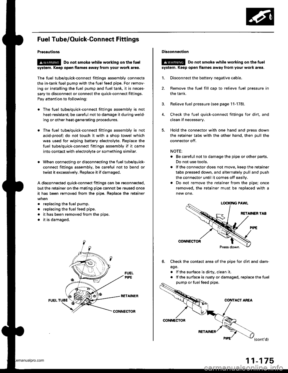
Fuel Tube/Ouick-Gonnect Fittings
Procautions
@ Do not smoke whils working on the fuel
syst6m, Koop open flames away from your work ar9a.
The fuel tube/quick-connect fittings assembly connects
the in-tank fuel pump with the fuel feed pipe. For remov-
ing or installing the fuel pump and fuel tank, it is neces-
sary to disconnect or connect the quick-connect fittings.
Pay attention to following;
. The fuel tube/quick-connect fittings assembly is not
heat-resistant; be careful not to damage it during weld-
ing or other heat-generating procedures.
. The fuel tube/quick-connect fittings assembly is not
acid-proof; do not touch it with a shop towel which
was used for wiping battery electrolyte. R€place the
fuel tube/quick-connect fittings assembly if it came
into contact with electrolyte or somethino similar.
. When connecting or disconnecting the fuel tube/quick-
connect fittings assembly, be careful not to bend or
twist it excessively, Replace it if damaged,
A disconnected quick-connect fittings can be reconnected,
but the retainer on the mating pipe cannot be reused once
it has been removed from the pipe. Replace tha retainer
. replacing the fuel pump.
. replacing the fuelfeed pipe,
. it has been removed from the Dioe,
. it is damaged.
RCTAINERFUEL TUBE
CONNECTOR
CONNECTOR
RETAINER
11-175
Disconnection
!@ Do not smoke while working on the fuel
syst6m. Keep open flames away from your work area.
1. Disconnect the battery negative cable.
2. Remove the fuel fill cap to relieve fuel pressure in
the tank.
3. Relieve fuel pressure (see page 11-178).
4. Check the fuel quick-connect fittings for dirt, and
clean if necessary.
5. Hold the connector with one hand and press down
the retainer tabs with the other hand. then pull the
connector off.
NOTE:
. Be careful not to damage the pipe or other parts.
Do not use tools,
. lf the connector does not move, keep the retainer
tabs pressed down, and alternately pull and push
the connector until it comes off easily.
. Do not remove the retainer from the pipe; once
removed, the retainer must be replaced with a
new one.
LOCKII{G PAWL
RETANEN TAB
@NNCCTOR
Press down.
6. Check the contact area of the pipe for dirt and dam-
age.
. lf the surface is dirW, clean it
. lf the surface is rusty or damaged, replace the fuel
pump or fuel feed pipe,
CONTACT ANEA
{cont'd}
www.emanualpro.com
Page 380 of 1395
Fuel Supply System
System Description
The fuel supply system consists of a fuel tank, in-tank
high-pressure fuel pump. PGM-Fl main relay, fuel filter,
fuel pressure regulator, fuel injectors, and fuel delivery
and return lines. This system delivers pressure-regulat-
ed fuel to the fuel injectors and cuts the fuel delivery
when the engine is not running.
Fuel Pressure
Relieving
Before disconnecting fuel pipes or hoses, release pres-
sure from the system by loosening the 12 mm banjo
bolt on the too of the fuel filter.
Do not smoke while working on the fuel system.
Ke€p open flames or sparks away from your work
area,
Be sure to relieve fuel pressure while the ignition
switch is off.
Write down the frequencies for the radio's preset
buttons.
Disconnect the battery negative cable from the bat-
tery negative terminal.
Remove the fuel fill cap.
Use a box end wrench on the 12 mm banjo bolt at
the fuel filter while holding the fuel filter with anoth-
er wrench.
Place a rag or shop towel over the '12 mm banjo bolt.
Slowly loosen the 12 mm banjo bolt one complete
rurn 12 mm BANJoBOLT
1.
SHOP TOWEL
NOTE: Replace the washers whenever the 12 mm
banio bolt is loosened or removed.
11-178
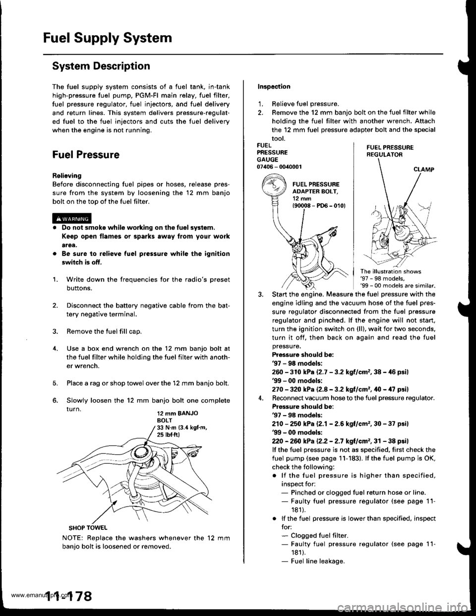
Inspection
1, Relieve fuel pressure.
2. Remove the 12 mm banjo bolt on the fuel filter while
holding the fuel filter with another wrench. Attach
the 12 mm fuel pressure adapter bolt and the special
tool.
FUEL PRESSUREREGULATON
FUELPRESSUREGAUGE07406 - 0040001
The illustration shows'97 - 98 models,'99 - 00 models are similar.
Start the engine. Measure the fuel pressure with the
engine idling and the vacuum hose of the fuel pres-
sure regulator disconnected from the fuel pressure
regulator and pinched. lf the engine will not start,
turn the ignition switch on (ll), wait for two seconds,
turn it off, then back on again and read the fuel
pressure.
Pressure should be:'97 - 98 mod€ls:
260 -31O kPa 12.7 - 3.2 kgf/cm,, 38 - 46 psil'99 - 0O models:
270 - 32O kPa Q.A - 3.2 kgf/cm'�, ifo - /U psil
Reconnect vacuum hose to the fuel pressure regulator.
Prgs3ure should be:'97 - 98 models:
210 - 25O kPa 12.1- 2.6 kgf/cm'�, 30 - 37 psi)'99 - 00 models:
22O -26iJ kPa 12.2 - 2.7 kgt/cm'�, 31 - 38 psi)
lf the fuel pressure is not as specified, first check the
fuel pump (see page 11- 183). lf the fuel pump is OK,
check the following:
. lf the fuel pressure is higher than specified,
inspect for:- Pinched or clogged fuel return hose or line.- Faulty fuel pressure regulator (see page 11-
181).
. lf the fuel pressure is lower than specified. inspect
for:- Clogged fuel filter.- Faulty fuel pressure regulator (see page 11-
1811.- Fuel line leakage.
www.emanualpro.com
Page 383 of 1395
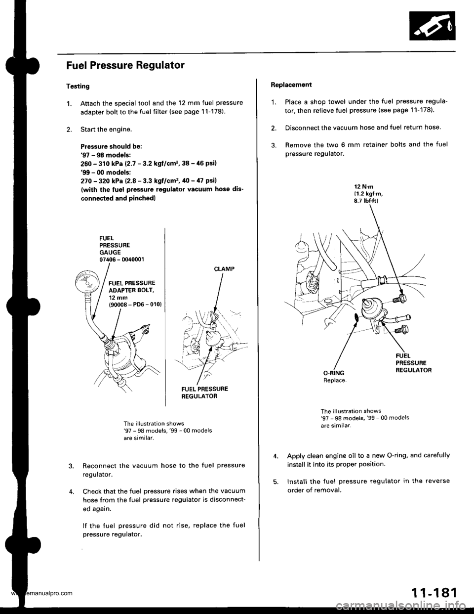
Fuel Pressure Regulator
Tesiing
1. Attach the special tool and the 12 mm fuel pressure
adapter bolt to the fuel filter (see page 1l-178)
2. Start the engine.
Prasgure should be:'97 - 98 models;
260 - 310 kPa (2.7 - 3.2 kgl/cm'�,38 -,16 psi)'9!t - 00 models:
27O - 32o kPa l2-8 - 3.3 kgf/cm'�, 40 - /l7 psil
(with the lugl pressure rsgulator vacuum hose dis-
connested and pinched)
FUELPRESSUREGAUGE07406 - 0040001
FUEL PRESSURENEGULATOR
The illustration shows'97 - 98 models,'99 -00 modelsare similar.
Reconnect the vacuum hose to the fuel pressure
regulalor.
Check that the fuel pressure rises when the vacuum
hose from the fuel pressure regulator is disconnect-
ed agarn.
lf the fuel pressure did not rise, replace the fuel
pressure regulator.
4.
CLAMP
Replacement
'1. Place a shop towel under the fuel pressure regula-
tor, then relieve fuel pressure (see page 11-1781.
2. Disconnect the vacuum hose and fuel return hose.
3. Remove the two 6 mm retainer bolts and the fuel
pressure reguralor.
12 N.m(1.2 kgf.m,8.7 tbf.ft)
The illustration shows'97 - 98 models, '99 00 models
are similar.
Apply clean engine oil to a new O-ring. and carefully
install it into its proper position.
Install the fuel pressure regulator in the reverse
order of removal,
Replace.
1 1-181
www.emanualpro.com