Pin HONDA CR-V 1999 RD1-RD3 / 1.G Service Manual
[x] Cancel search | Manufacturer: HONDA, Model Year: 1999, Model line: CR-V, Model: HONDA CR-V 1999 RD1-RD3 / 1.GPages: 1395, PDF Size: 35.62 MB
Page 384 of 1395
Fuel Supply System
Fuel Filter
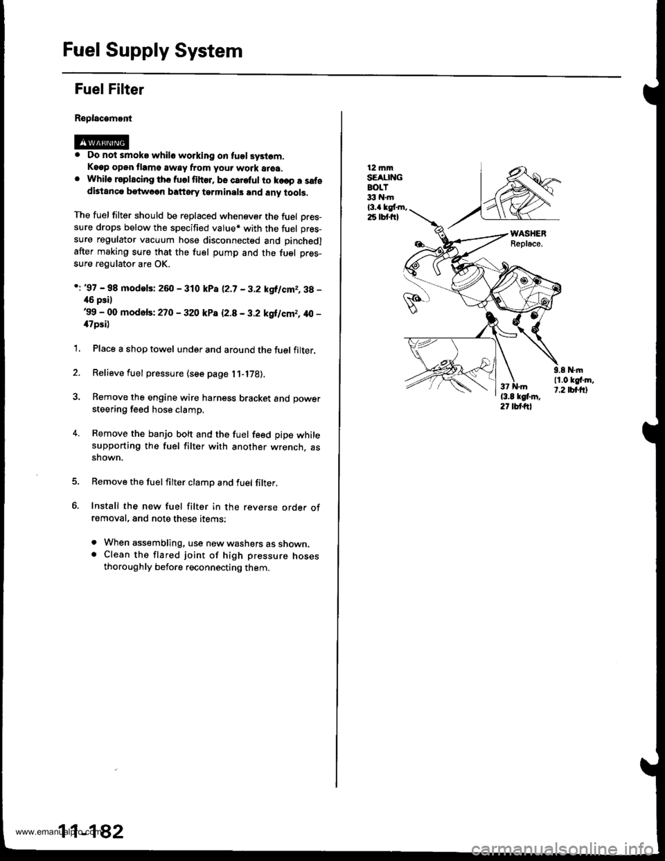
Replacamont
. Do not smoke whilo working on tuol syslom,Keep open flame away from your work area.. While rsplscing ths fuolfihor. bo careful to ko€p a safedistanca betweon baftsry tarminals and any tools,
The fuel filter should be replaced whenever the fuel Dres-sure drops below the specified value* with the fuel pres-
sure regulator vacuum hose disconnected and pinchedl
after making sure that the fuel pump and the fuel pres-
sure regulator are OK.
i: '97 - 98 modelsi 260 - 310 kPa 12.7 - 3.2 kgllcm2,3g -
46 psil'99 - 00 mod6fs: 270 - 320 kP8 12.8 - 3.2 kgilcm2, 40 -
il7psi)
1, Place a shop towel under and around the fuel filter.
2. Relieve fuel pressure (see page l1-l7B).
3. Remove the engine wire harness bracket and power
steering feed hose clamp.
4. Remove the banjo bolt and the fuel feed pipe whilesupporting the fuel filter with another wrench. assnown.
Remove the fuelfilter clamp and fuel filter,
Install the new fuel filter in the reverse orde. ofremoval, and note these items:
. When assembling, use new washers as shown.. Clean the flared joint of high pressure nosesthoroughly before reconnecting them.
11-182
12 mmSEAUNGBOLT33 hl.m
l3.a kgt m,25 lbt frl
9.8 N.|n11.0 kgf'm,t.2 tbt.ftl
www.emanualpro.com
Page 403 of 1395
Positive Grankcase Ventilation (PGVI System
Description
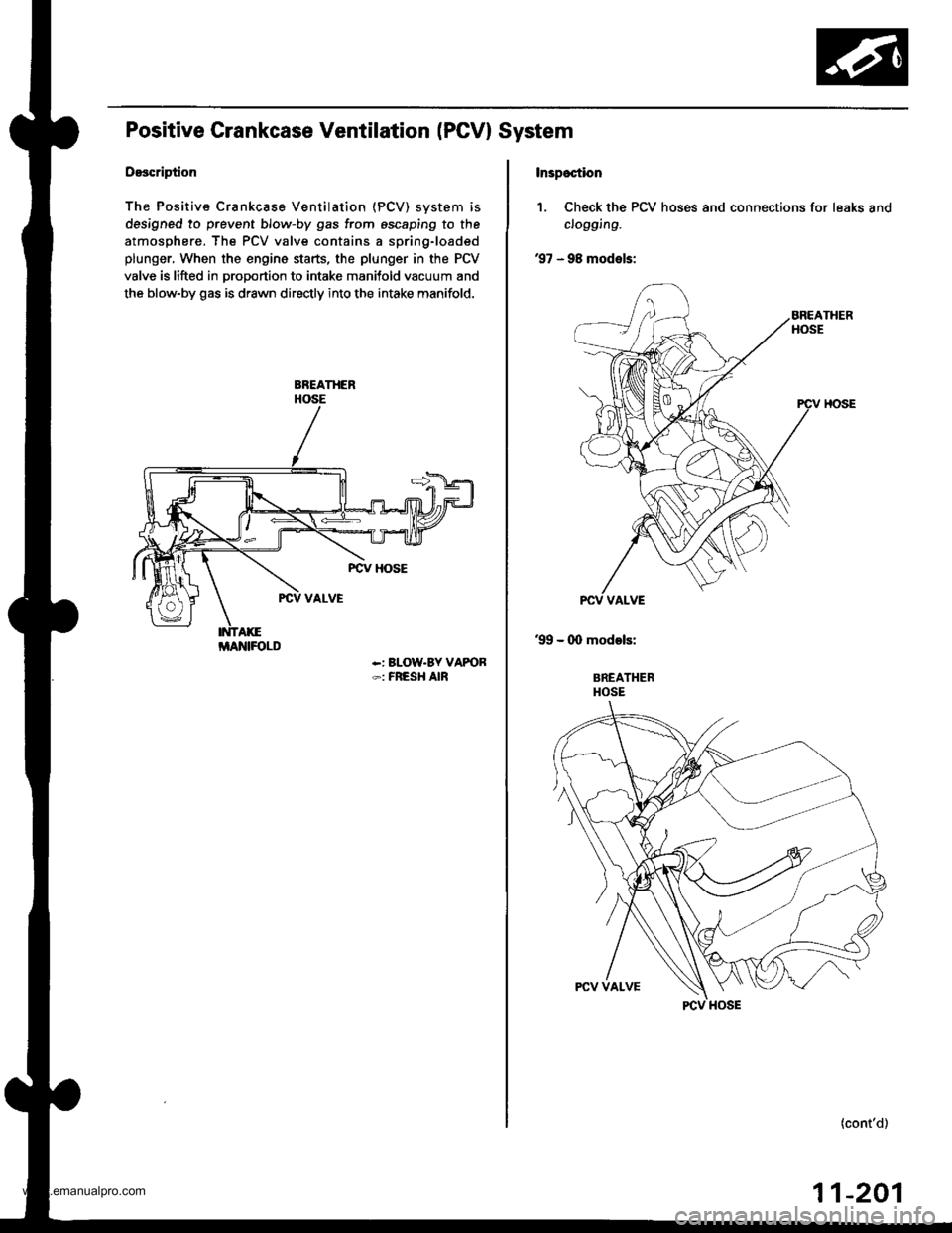
The Positive Crankcase Ventilation (PCV) svstem is
designed to prevent blow-by gas from escaping to the
atmosphere. The PCV valve contains a spring-loaded
plunger, When the engine starts, the plunger in the PCV
valve is lifted in proportion to intake manitold vacuum and
the blow-by gas is drawn directly into the intake manifold.
-: BLOW.BY VAPOR-: FRESH AIR
i/lAlrllFOLD
Inspoction
1. Check the PCV hoses and connections for leaks and
clogging.
'97 - 98 models:
'99 - (X) models:
BREATHERHOSE
(cont'd)
11-201
www.emanualpro.com
Page 404 of 1395
Emission Control System
Positive Crankcase Ventilation (PCV) System (cont'dl
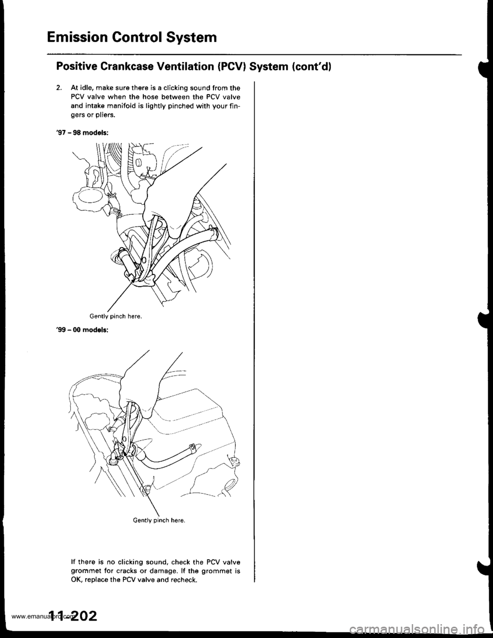
2. At idle, make sure there is a clicking sound from the
PCV valve when the hose between the PCV valve
and intake manifold is lightly pinched with your fin-
gers or pliers.
'97 - 98 models:
'99 - 00 modelsi
lf there is no clicking sound, check the PCV valvegrocrmet for cracks or damage, lf the grommet is
OK, reDlace the PCV valve and recheck.
Gently pinch here.
Gently pinch here.
11-202
www.emanualpro.com
Page 405 of 1395
EVAP PURGE CONTROL SOLENOID VALVE DUTY CONTROLLED AFTER
STARTING ENGINE
ENGINE COOLANT TEMPERATURE ABOVE 154"F (68'C)
Evaporative Emission (EVAP) Controls
Description:
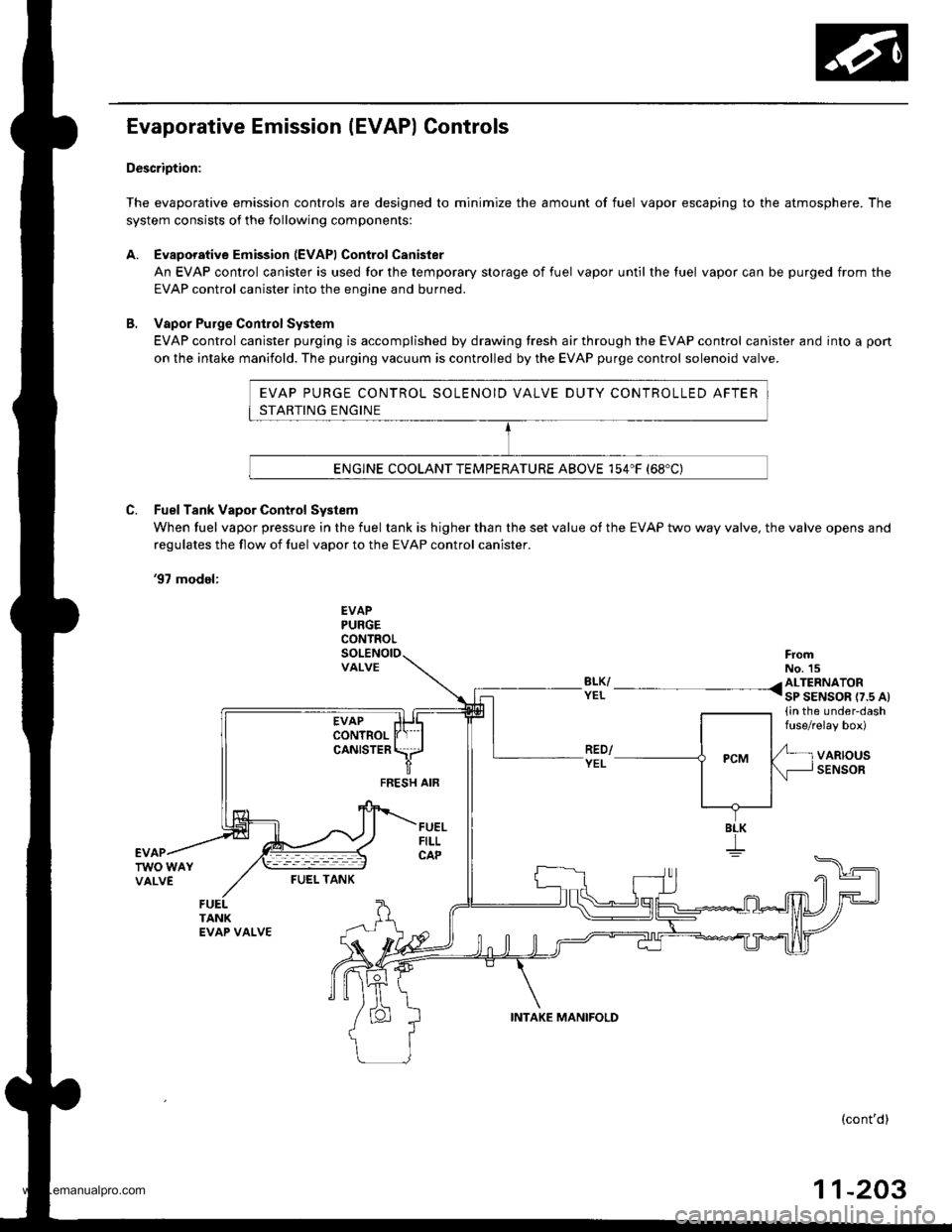
The evaporative emission controls are designed to minimize the amount of fuel vapor escaping to the atmosphere. The
system consists of the following components:
A. Evaporative Emission (EVAPI Control Canister
An EVAP control canister is used for the temporary storage of fuel vapor until the luel vapor can be purged from the
EVAP control canister into the enqine and burned.
B. Vapor Purge ConirolSystem
EVAP control canister purging is accomplished by drawing fresh air through the EVAP control canister and into a pon
on the intake manifold. The purging vacuum is controlled by the EVAP purge control solenoid valve.
C. Fuel Tank Vapor Control System
When fuel vapor pressure in the fuel tank is higher than the set value of the EVAP two way valve, the valve opens and
regulates the flow ot fuel vapor to the EVAP control canister.
'97 model:
EVAPPURGECONTROL
VALVEFromNo. 15BLK/ /ALTERNATORYEL I sP SENSOR r7.s At(in the under-dashfuse/relay box)
VARIOUSSENSORFEESH AIF
BLK
I
FUEI- TANK
(cont'd)
11-203
INTAKE MANIFOLD
www.emanualpro.com
Page 430 of 1395
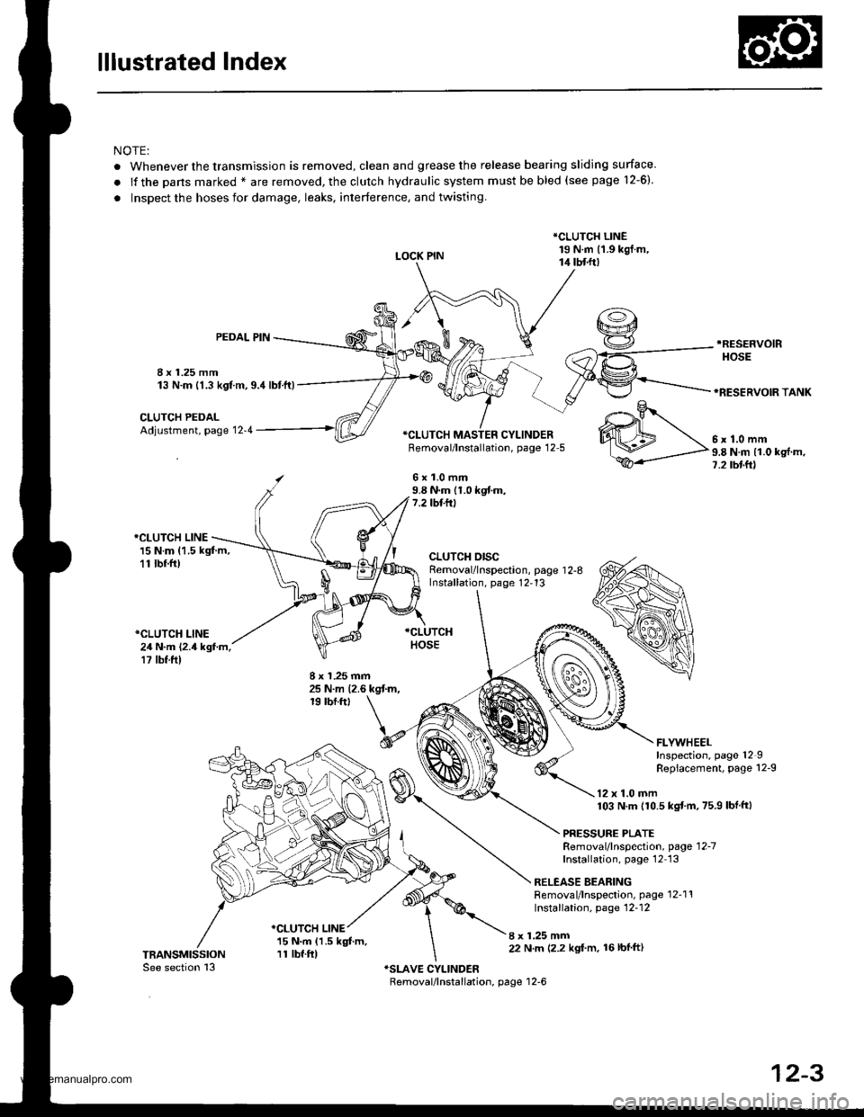
lllustrated Index
NOTE:
. Whenever the transmission is removed, clean and grease the release bearing sliding surface
.lfthepansmarked*areremoved,theclutchhydraulicsystemmustbebled(seepage1\
2-6).
. Inspect the hoses for damage. leaks. interference, and twisting.
LOCK PIN
*CLUTCH LINE19 N.m (1.9 kgj.m,14 tbtft)
8 x 1.25 mm13 N.m {1.3 kgf m,9.4lbtft)
PEDAL PIN.RESEFVOIR
HOSE
*RESERVOIR TANK
CLUTCH PEDALAdjustment, page 12-4*CI-UTCH MASTER CYLINDERFemoval/lnstallation, page 12-5
6x1.0mm9.8 N.m (1.0 kgf.m,7.2 tbf.ft)
*CLUTCH LINE15 N.m (1.5 kgt m,11 tbr.ft)
*CLUTCH LINE24 N.m {2.4 kgf.m,17 tbf.ft)
CLUTCH DISCRemoval/lnspection, page 1 2-8Installation, page 12,13
8 x 1.25 mm25 N.m {2.6 kgt m,19 rbf.ftt
I x 1.25 mm22 N.m 12.2 kgl'm, 16lbfft)
.o-.9r
WM\,".0--
ffi-P"8Nmlloks{m'
FLYWHEELInspection, page 12IRepiacement, page 12-9
12 x 1.0 mm103 N.m (10.5 kgtm,75.9 lbf ftl
PRESSURE PLATERemoval/lnspection, page'12-7
Installation, page'12 13
RELEASE BEARINGRemoval/lnspection, page 12-1'!Installation, page 12-12
*CLUTCH LINE15 N.m (1.5 kgt m,11 tbf.ft)
12-3
www.emanualpro.com
Page 432 of 1395
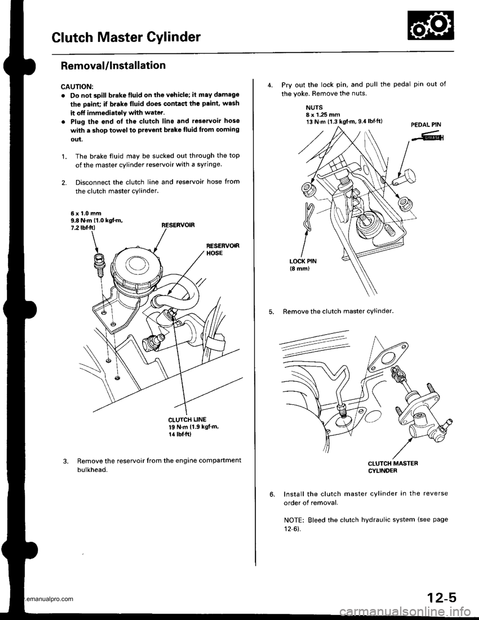
Glutch Master Cylinder
Removal/lnstallation
CAUTION:
. Do not spill brake fluid on the vehicle; it may damage
the paint; if brake tluid does contact the paint. wash
it off immediately with water.
. Plug the end ol the clutch line and leservoir hose
with a shop towel to prevent brake tluid trom coming
out.
The brake fluid may be sucked out through the top
of the master cylinder reservoir with a syringe.
Disconnect the clutch line and reservoir hose from
the clutch master cylinder,
't.
9.8 N.m 11.0 kst m,7.2 tbf.ftl
CLUTCH LINE
19 N'm 11 9 kgJ m'
14 lbf.frl
Remove the reservoir from the engine compartment
bulkhead.
13 N.m t1.3 kgt.m,g.il lbtft)
4. Prv out the lock pin, and pull the pedal pin out of
the voke. Remove the nuts.
NUTSI x 1.25 mm
5, Remove the clutch master cylinder.
CLUTCH MASTERCYLINDEF
Install the clutch master cylinder in the reverse
order of removal.
NOTE: Bleed the clutch hydraulic system {see page
12-61.
12-5
www.emanualpro.com
Page 434 of 1395
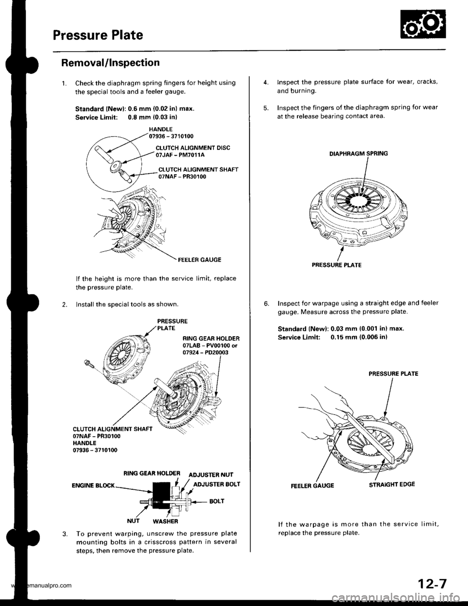
Pressure Plate
Removal/lnspection
1.Check the diaphragm spring fingers for height using
the special tools and a feeler gauge.
Standard lNewl: 0.6 mm {0.02 in) max.
Service Limit: 0.8 mm (0.03 in)
HANDLE07936 - 3710100
CLUTCH ALIGNMENT DISCOTJAF - PM7O11A
CI.UTCH ALIGNMENT SHAFT07NAF - PR30100
FEELER GAUGE
lf the height is more than
the pressure Plate.
the service limit, replace
2. lnstall the sDeciallools as shown.
RING GEAR HOLDER ADJUSTER NUT
ENGINE BLOCKADJUSTER BOLT
BOLT
NUT WASHER
To prevent warping, unscrew the pressure plate
mounting bolts in a crisscross pattern in several
steps. then remove the pressure plate.
4. Inspect the pressure plate surface for wear, cracks,
and burning.
5. Inspect the fingers of the diaphragm spring for wear
at the release bearing contact area.
Inspect for warpage using a straight edge and feeler
gauge. Measure across the pressure plate.
Standard lNew): 0.03 mm 10.001 in) max.
Service Limit: 0.15 mm (0.006 inl
6.
FEELER GAUGE
lf the warpage is more than the service limit,
replace the pressure plate.
PRESSURE PLATE
PRESSURE PLATE
12-7
www.emanualpro.com
Page 435 of 1395
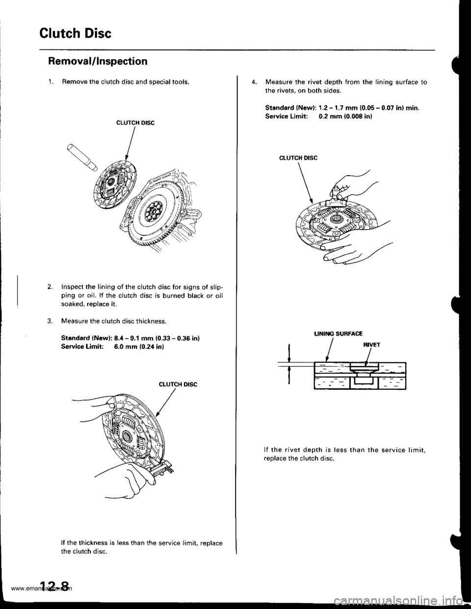
Glutch Disc
Removal/lnspection
'1. Remove the clutch disc and specialtools.
CLUTCH DISC
Inspect the lining of the clutch disc for signs of slip-ping or oil. lf the clutch disc is burned black or oil
soaked, replace it.
Measure the clutch disc thickness.
Standard (New): 8.,1- 9.1 mm (0.33 - 0.36 in)
Service Limh: 6.0 mm (0.2,1 in)
CLUTCH DISC
lf the thickness is less than the service limit, reDlace
the clutch disc.
12-8
4. Measure the rivet depth from the lining surface to
the rivets, on both sides.
Standard (New): 1.2 - 1.7 mm 10.05 - 0.07 in) min.
Service Limit: 0.2 mm {0.008 inl
lf the rivet depth is less than
replace the clutch disc.
the service limit,
LINI G SURFACE
www.emanualpro.com
Page 437 of 1395
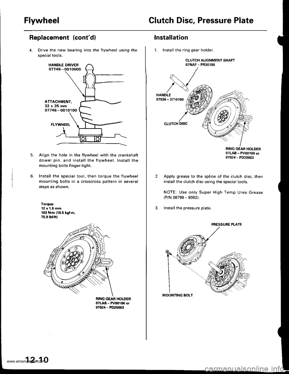
FlywheelClutch Disc, Pressure Plate
Replacement (cont'dl
Drive the new bearing
specialtools.
HANOLE DRIVER07749-
ATTACHMET{T-32x35mm07746 -O010100
FLYWHECI-
Align the hole in the flywheel with the crankshaft
dowel pin, and install the flywheel. Install the
mounting bolts finger-tight.
Install the special tool, then torque the flywheel
mounting bolts in a crisscross pattern in several
steps as shown.
Torque:12 x 1.0 mmr03 N.m (10.5 kgl.ln,75.9 tbtftl
into the flywheel using the
12-10
Installation
1. Install the ring gear holder.
CLUTCH ALIGNMENT SHAFT07NAF - PR30100
CLUTCH DISC
RING GEAR HOLDER07LAB _ pvoot(x) or07924 _ PD20003
Apply grease to the spline of the clutch disc, then
install the clutch disc using the special tools.
NOTE: Use only Super High Temp Urea Grease(P/N 08798 - 9002).
lnstall the pressure plate.
PRESSURE PLATE
www.emanualpro.com
Page 438 of 1395
Release Bearing
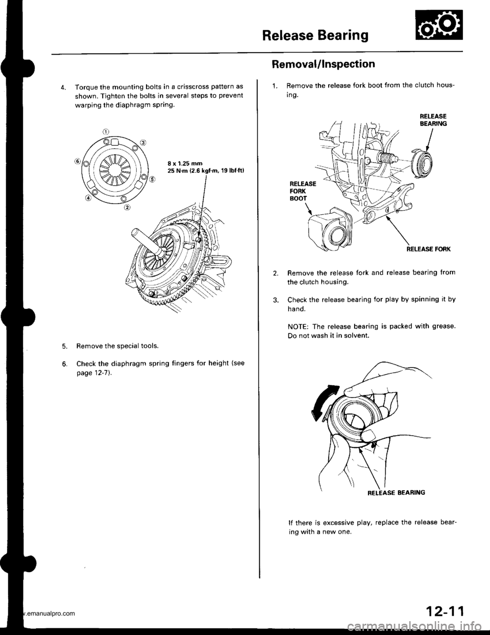
4. Torque the mounting bolts in a crisscross pattern as
shown. Tighten the bolts in several steps to prevent
warping the diaphragm spring.
8 x 1.25 mm25 N.m (2.6 kgf.m, 19lbfft)
Remove the special tools.
Check the diaphragm spring fingers for height (see
page 12-7]'.
5.
6.
Removal/lnspection
1. Remove the release fork boot from the clutch hous-
Ing.
RELEASEBEABING
RELEASEFORKBOOT
\
RELEASE FORK
Remove the release fork and release bearing from
the clutch housing.
Check the release bearing for play by spinning it by
ha nd.
NOTE: The release bearing is packed with grease.
Do not wash it in solvent.
lf there is excessive play, replace the release bear-
ing with a new one.
12-11
www.emanualpro.com