Pin HONDA CR-V 1999 RD1-RD3 / 1.G User Guide
[x] Cancel search | Manufacturer: HONDA, Model Year: 1999, Model line: CR-V, Model: HONDA CR-V 1999 RD1-RD3 / 1.GPages: 1395, PDF Size: 35.62 MB
Page 102 of 1395
Engine Removal/lnstallation
Removal (cont'd)
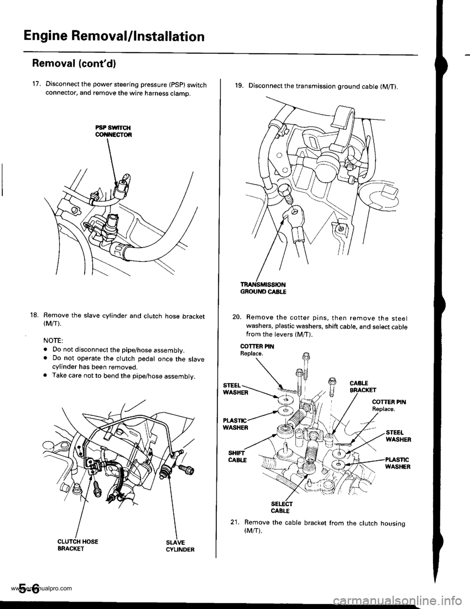
17. Disconnect the power steering pressure {psp} switchconnector, and remove the wire harness clamo.
Remove the slave cylinder and clutch hose bracket(Mrr).
NOTE:
. Do not disconnect the pipe/hose assembly.. Do not operate the clutch pedal once the slavecylinder has been removed.. Take care not to bend the pipe/hose assembly.
5-6
18.
19. Disconnect the transmission ground cable (M/T).
Remove the cotter pins, then remove the steelwashers, plastic washers, shift cable, and select cablefrom the levers (M/T).
sElEcrCABI."E
21. Remove the cable bracket from the clutch housing(M/T).
GROUND CABI."E
www.emanualpro.com
Page 104 of 1395
Engine RemovaUlnstallation
OOI{TROL PI
Removal (cont'dl
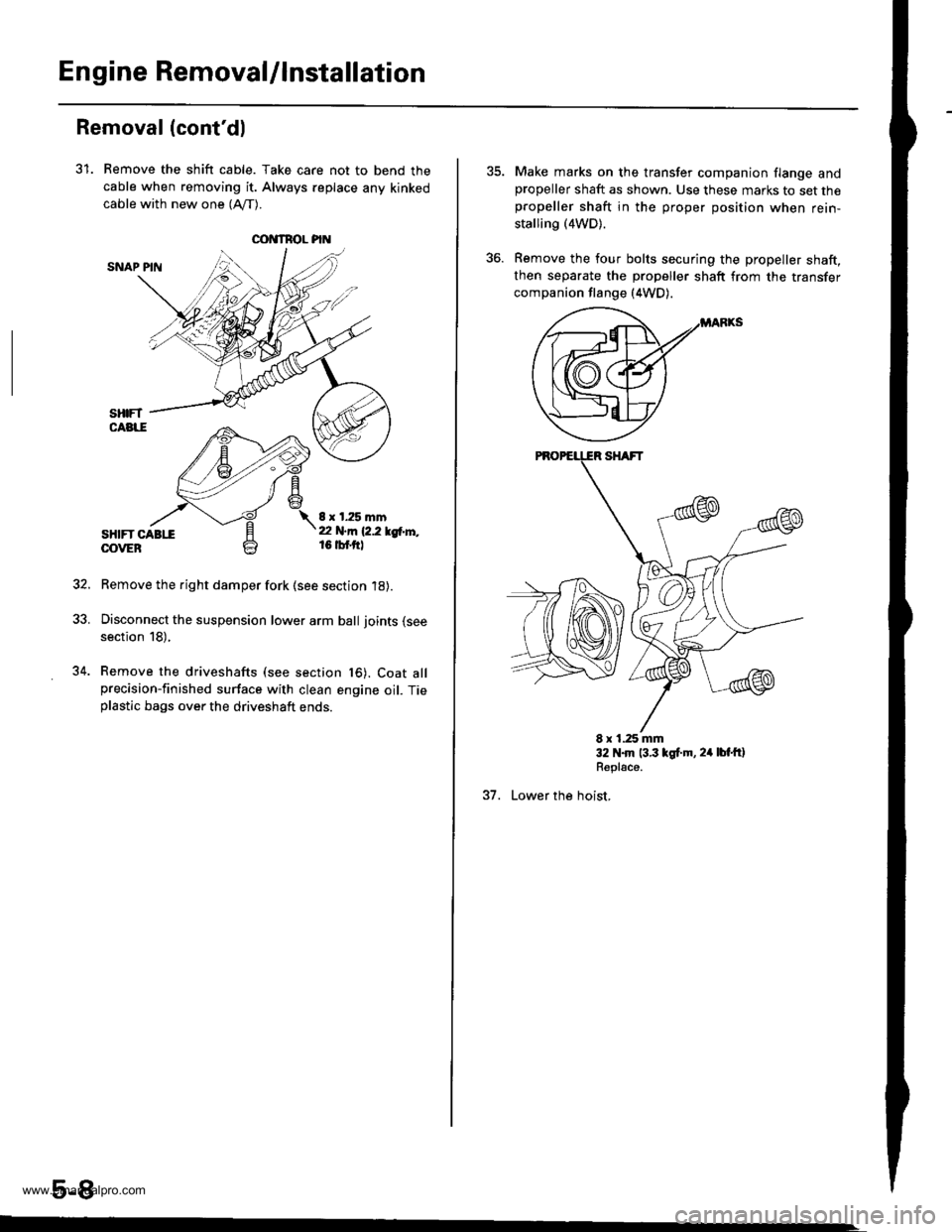
31. Remove the shift cable. Take care not to bend the
cable when removing it. Always replace any kinked
cable with new one (Afl-).
SNAP PIN
sHtFT CABttOOVEB
8 x 1.25 mmt2 N.m 12.2 lgtr'l'',,16 tbf.ftl
Remove the right damper fork (see section 18).
Disconnect the suspension lower arm ball joints (see
section 18),
Remove the driveshafts (see section t6). Coat allprecision-finished surface with clean engine oil. Tieplastic bags over the driveshaft ends.
5-8
34.
Make marks on the transfer companion flange andpropeller shaft as shown. Use these marks to set thepropeller shaft in the proper position when rein-
stalling (4WD).
Remove the four bolts securing the propeller shaft,then separate the propeller shaft from the transfer
companion flange (4WD).
E x 1.25 mm32 N.m 13.3 lgt.m, 24 lbt'ftlRepl€ce.
37. Lower the hoist,
www.emanualpro.com
Page 118 of 1395
Valve Seals
Replacement (cylinder head removal not required)
The procedure shown below applies when using the in-
car valve spring compressor (Snap-on YA8845 with
YA8845-2A 7/8" auachment). Use approved eye protec-
tion.
1. Turn the crankshaft so that the No. 1 and the No. 4
pistons are at top dead center (TDC).
2. Remove the cylinder head cover.
3. Remove the distributor.
4. Loosen and disconnect the timing belt from the
camshaft pulleys.
5. Remove the camshaft holder bolts. then remove the
camshaft holders, the camshafts and rocker arms.
lntake Valve Seals
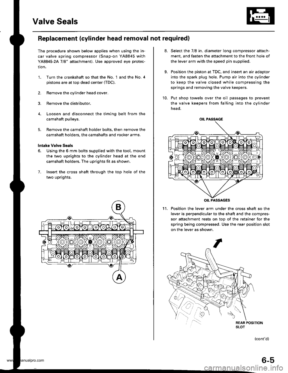
6. Using the 6 mm bolts supplied with the tool, mount
the two uprights to the cylinder head at the end
camshaft holders. The uprights fit as shown.
7. Insert the cross shaft through the top hole of the
two uprights,
at.
9.
Select the 7/8 in. diameter long compressor attach-
ment, and fasten the attachment to the front hole of
the lever arm with the speed pin supplied.
Position the piston at TDC, and insen an air adaptor
into the spark plug hole. Pump air into the cylinder
to keep the valve closed while compressing the
springs and removing the valve keepers.
10. Put shop towels over the oil passages to prevent
the valve keepers from falling into the cylinder
head.
Position the lever arm under the cross shaft so the
lever is perpendicular to the shaft and the compres-
sor attachment rests on top of the retainer for the
spring being compressed. Use the rear position slot
on the lever as shown,
't1.
OIL PASSAGE
OIL PASSAGES
(cont'd)
6-5
www.emanualpro.com
Page 119 of 1395
Valve Seals
12.
Replacement (cylinder head removal not requiredl (cont'dl
Using an upward motion on the lever arm, compress
the valve spring and remove the keepers from the
valve stem. Slowly release pressure on the spring.
Repeat step 11 for the other valve in that cylinder.
Remove the valve seals (see page 6-24).
Installthe valve seals (see page 6-29).
lnstall the springs, the retainers and the keepers in
reverse order of removal.
'17. Repeat steps 9 to 16 for the other three cylinders.
Exhaust valve Seals
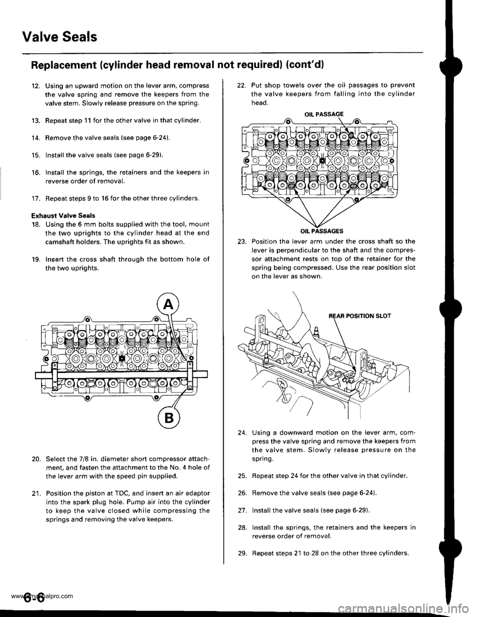
18. Using the 5 mm bolts supplied with the tool, mount
the two uprights to the cylinder head at the end
camshaft holders. The uprights fit as shown.
19. Insert the cross shaft through the bottom hole of
the two uprights.
Select the 7/8 in. diameter short compressor attach
ment, and fasten the attachment to the No. 4 hole of
the lever arm with the speed pin supplied.
Position the piston at TDC, and insert an air adaptor
into the spark plug hole. Pump air into the cylinder
to keep the valve closed while compressing the
springs and removing the valve keepers.
13.
14.
15.
16.
20.
t1
22. Put shop towels over the oil passages to prevent
the valve keepers from falling into the cylinder
neao.
23. Position the lever arm under the cross shaft so the
lever is perpendicular to the shaft and the compres-
sor attachment rests on top of the retainer for the
spring being compressed. Use the rear position slot
on the lever as shown.
Using a downward motion on the lever arm, com-
press the valve spring and remove the keepers from
the valve stem. Slowly release pressure on the
spring.
Repeat step 24 for the other valve in that cylinder.
Remove the valve seals (see page 6-24).
Install the valve seals (see page 6-29).
Install the springs, the retainers and the keepers in
reverse order of removal.
Repeat steps 21 to 28 on the other three cylinders.
24.
21.
28.
29.
o-o
www.emanualpro.com
Page 127 of 1395
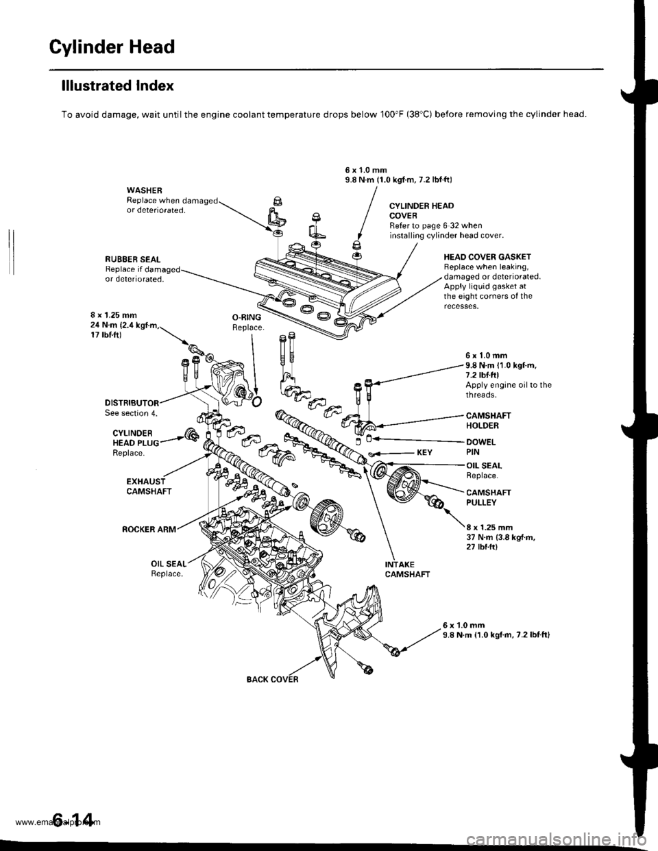
Gylinder Head
lllustrated Index
To avoid damage, wait until the engine coolant temperature drops below 100'F (38'C) before removing the cylinder head.
6x1.0mm9.8 N.m (1.0 kgI.m, 7.2 lbf.ft)WASHERReplace when damagedor deteriorated,CYLINDER HEADCOVEBReter to page 6 32 wheninstalling cylinder head cover.
HEAO COVER GASKETBeplace when leaking,damaged or deteriorated.Apply liquid gasket atthe eight corners of the
RUBEER SEALReplace ifor deteriorated,
8 x 1.25 mm24 N.m (2.4
17 tbtft)
See section 4.
CYLINDEBHEAD PLUGReplace-
---..-@0+---.."...-
s<-- KEY
6x1.0mm9.8 N.m (1.0 kgf.m.7.2 tbf.foApply engine oil to thethreads.
CAMSHAFTHOLDER
DOWELPIN
OIL SEALReplace.
CAMSHAFTPULLEY
8 x 1.25 mm37 N.m {3.8 kgf.m,27 tbtft)
OIL SEALReplace.
6x1.0mm9.8 N.m (1.0 kgl.m, 7.2lbtftl
6-14
www.emanualpro.com
Page 128 of 1395
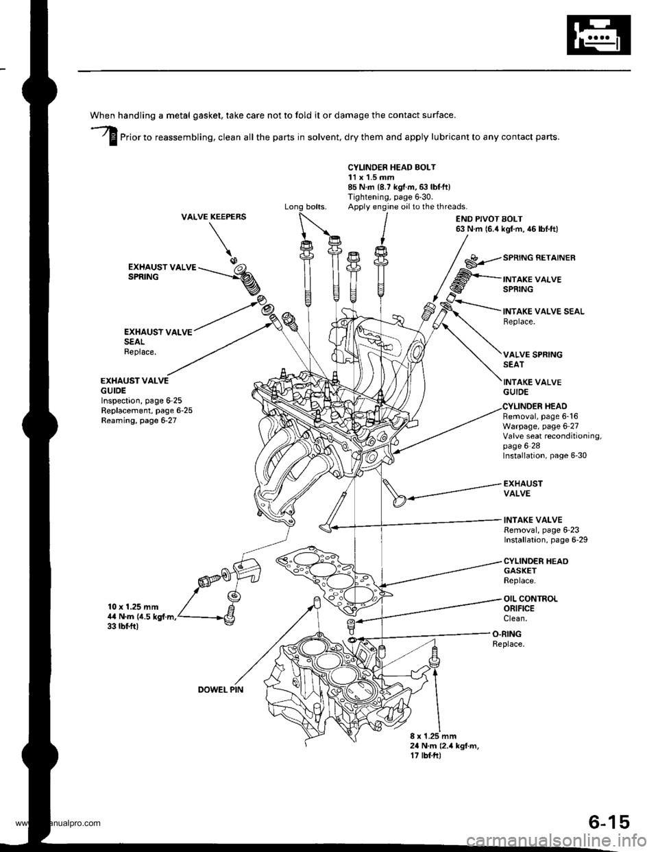
-?E
handling a metal gasket. take care not to fold it or damage the contact surface.
Prior to reassembling, clean all the parts in solvent, dry them and apply lubricant to any contact parts.
CYLINDER HEAD BOLT11 x 1.5 mm85 N.m {8.7 kgf.m,6:} lbf.ft)Tightening, page 6'30.Apply engine oilto the threads.VALVEKEEPERS
\
END PIVOT BOLT63 N.m 16.4 kgl m, 46 lbf.ft)
EXHAUSY VALVESEALReplace.
EXHAUST VALVEGUIDEInspection, page 6-25Replacem6nt, page 6-25Reaming, page 6-27
10 x 1.25 mm4,0 N.m {i1.5 kgf.m.33 rbf.ft)
GASKETReplace.
OIL CONTROLORIFICEClean.
EXHAUST VALVESPRING
SPRING BETAINER
INTAKE VALVESPRING
INTAKE VALVE SEALReplace.
VALVE SPRINGSEAT
INTAKE VALVEGUIDE
Removal, page 6-16Warpage, page 6 27Valve seat reconditioning,page 6 28Installation, page 6-30
EXHAUSTVALVE
INTAKE VALVERemoval, page 6-23Installation, page 6-29
CYLINDER HEAO
HEAD
O.RINGReplace.
8 x 1.25 mm24 N.m (2.4 kgf.m,17 tbf.ft)
DOWEL PIN
6-15
www.emanualpro.com
Page 143 of 1395
Cylinder Head
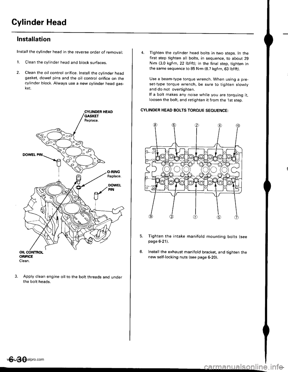
Installation
Installthe cylinder head in the reverse order of removal:
1. Clean the cylinder head and block surfaces.
2. Clean the oil control orifice. Install the cylinder headgasket, dowel pins and the oil control orifice on thecylinder block. Always use a new cylinder head gas-ket.
CYLII{DER HEADGASKETR€place.
DOWEL PIN
O.RINGRoplace.
DOWELPIN
OIL CONTBOLORIFICEClean.
Apply clean engine oil to the bolt threads and underthe bolt heads.
4. Tighten the cylinder head bolts in two steps. In thefirst step tighten all bolts, in sequence, to about 29
N.m {3.0 kgf.m,22 lbf.ft); in the finat step, tighten inthe same sequence to 85 N.m (8.7 kgf.m,63 lbf.ft).
Use a beam-type torque wrench. When using a pre-
set-type torque wrench, be sure to tighten slowly
and do not overtighten.
lf a bolt makes any noise while you are torquing it,loosen the bolt, and retighten it from the 1st step.
CYLINDER HEAD BOLTS TOROUE SEOUENCE:
Tighten the intake manifold mounting bolts (see
page 6-21).
Install the exhaust manifold bracket. and tighten thenew self-locking nuts (see page 6-20).
6-30
www.emanualpro.com
Page 145 of 1395

Cylinder Head
Installation (cont'dl
'13. Align the marks on the cylinder head plug to thecylinder head upper surface, then install the cylin
der head plug in the end of the cylinder head.
CYLINOER HEADPLUGReplace.
lnstallthe back cover.
To set the camshafts at TDC position for the No. lpiston, align the holes in the camshafts with theholes in the No. l camshaft holders and insert 5.0mm pin punches in the holes. Install the keys into
the camshaft grooves.
37 N m (3.8 *gl.m, 27 lbt.tr)
9.8 N.m (1.0 kgtm,7.2|hrftl
Push the camshaft pulleys onto the camshafts. thentighten the retaining bolts to the torque specified.
6-32
14.
KEYS
I x 1.25 mm
6x1.0mm
Install the timing belt (see page 6-1 1).
Adjust the valve clearance (see page 6-3).
Thoroughly clean the head cover gasket and thegroove.
lnstall the head cover gasket in the groove of thecylinder head cover. Seat the head cover gasket in
the recesses for the camshaft first, then work it into
the groove around the outside edges. Make sure thehead cover gasket is seated securely in the corners
of the recesses with no gap.
17.
'18.
19.
www.emanualpro.com
Page 147 of 1395
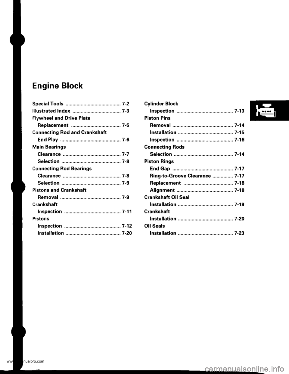
Engine Block
Speciaf Tools .............7-2
lllustrated lndex ................................... 7-3
Flywheel and Drive Plate
Replacement ..,.,....7-5
Connecting Rod and Grankshaft
End Play .................7-6
Main Bearings
Cfearance ...............7 -7
Selection ................7-8
Connecting Rod Bearings
Clearance ...............7-8
Selection ................7-9
Pistons and Crankshaft
Removal .................7-9
Crankshaft
Inspection .............. 7-11
Pistons
fnspection ..............7-12
fnstaflation .............7-20
Cylinder Block
Inspection ..............7-13
Piston Pins
Removal ..,.......,,..... 7-14
Installation ............. 7-15
Inspection .............. 7-16
Connecting Rods
Selection ................7 -14
Piston Rings
End Gap .................7 -17
Ring-to-Groove Clearance ............... 7 -17
Replacement .........7-18
Alignment .............. 7-18
Crankshaft Oil Seal
lnstallation ............. 7-19
Crankshaft
lnstalfation .............7-20
Oil Seals
fnstalfation ....,..,.....7-23
www.emanualpro.com
Page 148 of 1395
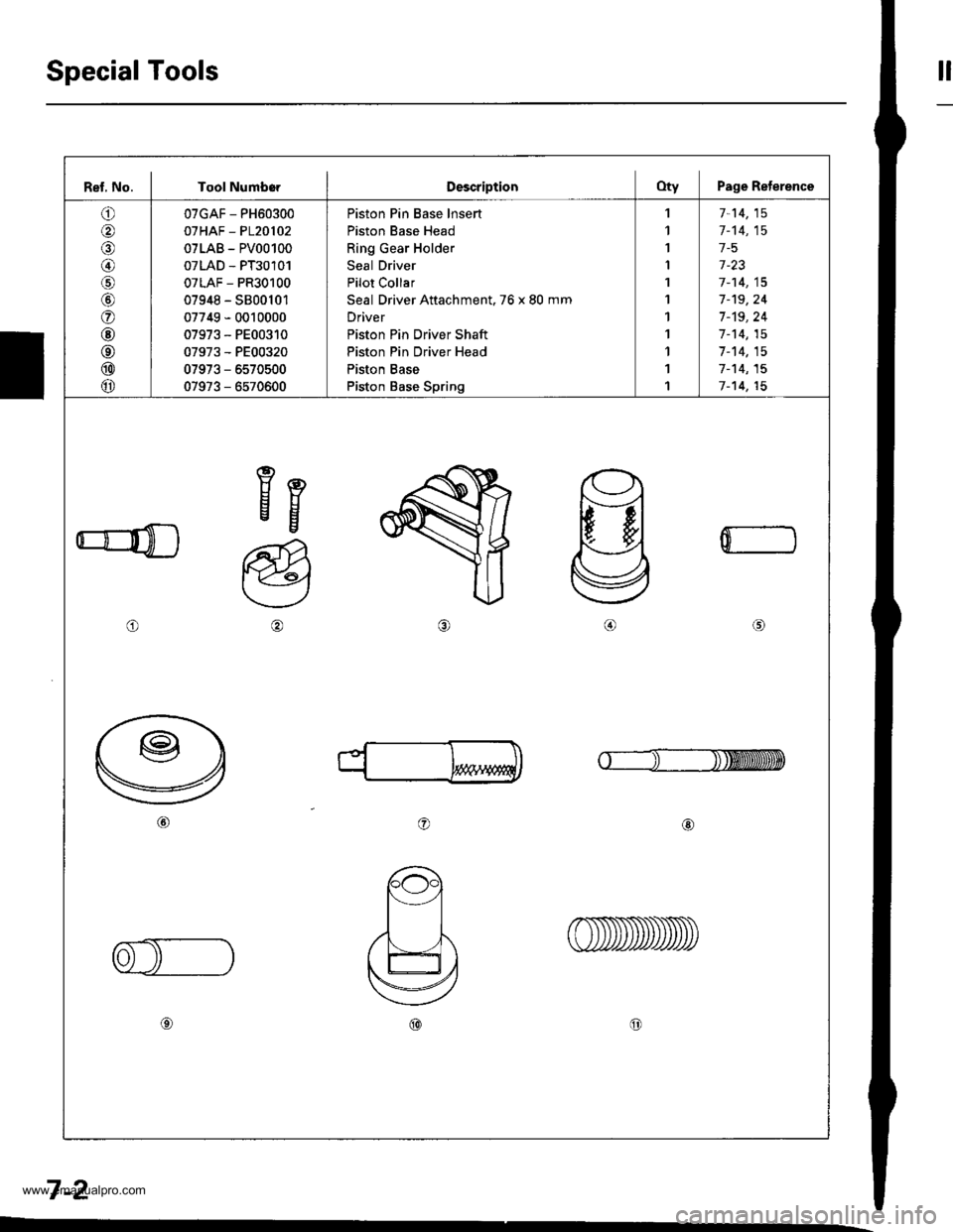
Special Toolstl
Ref, No. I Tool NumborDescriptionOty Page Reterence
o
@
@/6
@
o
@
@
@
@
07GAF - PH60300
07HAF - P120102
07LAB - PV00100
07LAD - PT30101
07LAF - PR30100
07948 - S800101
07749 - 0010000
07973 - PE00310
07973 - PE00320
07973 - 6570500
07973 - 6570600
Piston Pin Base lnsert
Piston Base Head
Ring Gear Holder
Seal Driver
Pilot Collar
Seal Driver Attachment. 76 x 80 mm
Driver
Piston Pin Driver Shaft
Piston Pin Driver Head
Piston Base
Piston Base Spring
,l
1
I
I
1
1
1
1
1
1
1
7-14,15
1-'t4,15
1-5
1-23
7-14,15
7-'t9,24
7 -'t9, 24
1-14,15
7-14,15
7-'t4,15
7-14,15
eEEg
o
a@
0
o@
7-2
www.emanualpro.com