drain plug HONDA CR-V 1999 RD1-RD3 / 1.G Workshop Manual
[x] Cancel search | Manufacturer: HONDA, Model Year: 1999, Model line: CR-V, Model: HONDA CR-V 1999 RD1-RD3 / 1.GPages: 1395, PDF Size: 35.62 MB
Page 103 of 1395
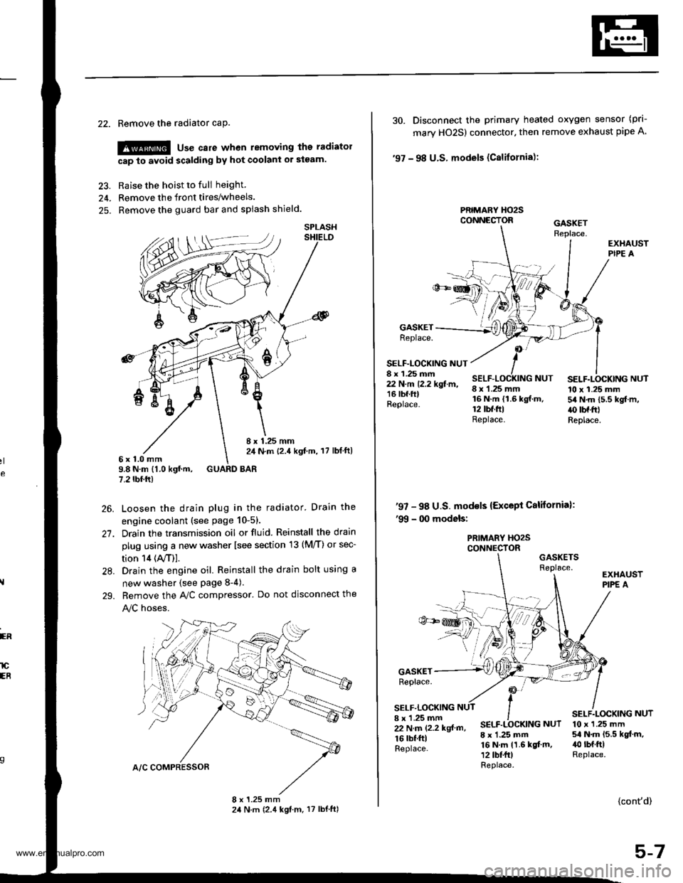
22. Remove the radiator caP.
!@ use care when removing the radiatol
cap to avoid scalding by hot coolani or steam.
23. Raise the hoist to full height
24. Remove the front tires/wheels.
25. Remove the guard bar and splash shield.
8 x 1.25 mm2,1 N.m {2.4 kgf,m, 17 lbl ft)6x1.0mm9.8 N.m {1.0 kgf.m, GUARD BAR7.2 tbf.rr)
Loosen the drain plug in the radiator. Drain the
engine coolant (see page 10-51.
Drain the transmission oil or fluid. Reinstall the drain
plug using a new washer lsee section 13 (M/T) or sec-
tion 14 (ly'T)].
Drain the engine oil. Reinstall the drain bolt using a
new washer {see page 8-4).
Bemove the A,/C compressor. Do not disconnect the
!y'C hoses.
SPLASH
26.
27.
28.
29.
ER
lCEB
30. Disconnect the primary heated oxygen sensor (prl-
mary HO2S) connector. then remove exhaust pipe A
'97 - 98 U.S. models (Cslifornia):
PRIMARY HO2SCONNECTOR
GASKETReplace.
SELF-LOCKING NUT8 x 1.25 mm22 N.m 12.2 kgf.m,16 lbf.ftlReplace.
8 x 1.25 mm16 N.m {1.6 kgf.m.12 tbt.ftlReplace.
SELF.LOCKING NUT10 x 1.25 mm54 N.m 15.5 kgf.m,.() tbf.frlReplace.
NUT
'97 - 98 U.S. mod€ls {Except California):'99 - 00 models:
PRIMARY HO2SCONNECTORGASKETSReplace.
GASKETReplace.
SELF.LOCKING8 x 'l.25 mm22 N.m (2.2 kgf m,
16 rbf.ftlReplace.
SELF.LOCKING NUT
8 x 1.25 mm16 N.m 11.6 kgf.m,12 tbt fr)Replace.
10 x 1.25 mm54 N.m 15.5 kgt.m,40 rbt.ftlReplace.
{cont'd)
5-7
www.emanualpro.com
Page 129 of 1395
Gylinder Head
Removal
Engine removal is not required for this procedure.
l!@ Make sure iacks and safety stands are
placed properly, and hoist blackels ale attachgd to the
correct position on the engine.
NOTE:
o Use fender covers to avoid damaging painted sur-
faces.
o To avoid damage, unplug the wiring connectors care-
fully while holding the connector portion.
. To avoid damaging the cylinder head, wait until the
engine coolant temperature drops below 100"F (38'C)
before loosening the retaining bolts.
. Mark all wiring and hoses to avoid misconnection.
Also, be sure that they do not contact other wiring or
hoses, or interfere with other parts.
2.
4.
5.
1.Disconnect the negative terminal from the battery.
Drain the engine coolant (see page 10-5). Remove
the radiator cap to speed draining.
Remove the intake air duct and air cleaner housing(see page 5-2).
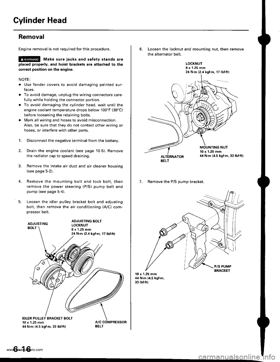
Remove the mounting bolt and lock bolt, then
remove the power steering (P/S) pump belt and
pump (see page 5-4).
Loosen the idler pulley bracket bolt and adjusting
bolt, then remove the air conditioning (A,/C) com,
pressor belt.
ADJUSTINGBOLT
ADJUSTING BOLTLOCKNUT8 x 1.25 mm24 N m {2.4 ksf.m, 17 lbttt}
IOLER PULLEY BBACKET BOLT10 x 1.25 mm44 N.m {4.5 kgtm, 33 lbf ft)
tt aAo-Io
6. Loosen the locknut and mounting nut, then remove
the alternator belt.
LOCKNUT8 x 1.25 mm24 N.m (2.4 kgf.m, 17 lbt.ftl
10 x 1.25 mm44 N.m (4.5 kgt.m. 33 lbf.ft)
7. Remove the P/S OUmo bracket.
l0 x 1.25 mm44 N.m (4.5 kgf.m,33 rbf.ft)
BELT
www.emanualpro.com
Page 174 of 1395
Engine Oil
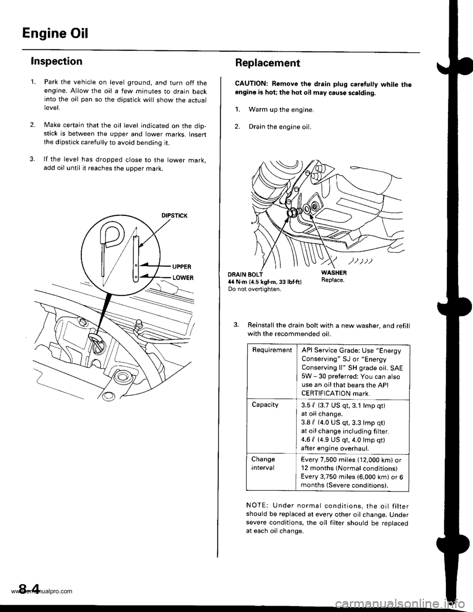
Inspection
2.
1.Park the vehicle on level ground, and turn off theengine. Allow the oil a few minutes to drain backinto the oil pan so the dipstick will show the actuallevet,
Make certain that the oil level indicated on the dip-stick is between the upper and lower marks. Insertthe dipstick carefully to avoid bending it.
lf the level has dropped close to the lower mark,add oil until it reaches the upper mark.
8-4
Replacement
CAUTION: Remove the drain plug caretuly white theengino is hot; the hot oil may cause scalding.
1. Warm up the engine.
2. Drain the engine oil.
WASHERR€place.ORAIN BOL4il N.m {4.5 kgtm,33 lbf.ft)Do not overtighten.
3. Reinstall the drain bolt with a new washer, and refill
with the recommended oil.
RequirementAPI Service Grade: Use "Energy
Conserving " SJ or "Energy
Conserving ll" SH grade oil. SAE
5W - 30 preferred: You can also
use an oil that bears the API
CERTIFICATION mark.
Capacity3.5 { (3.7 US qt,3.1 lmp qt)
at oil change.
3.8 / (4.0 US qt,3.3 lmp qr)
at oil change including filter.
4.6 { (4.9 US qt, 4.0 lmp qt)
after engine overhaul.
Change
Inlerval
Every 7,500 miles (12,000 km) or12 months (Normal conditions)
Every 3,750 miles (6,000 km) or 6months (Severe conditions).
NOTE: Under normal conditions, the oil filtershould be replaced at every other oil change. Undersevere conditions, the oil filter should be replacedat each oil change.
www.emanualpro.com
Page 192 of 1395
Radiator
1.
2.
3.
4.
Replacement
CONDENSERFAN,/SHROUDASSEMBLY
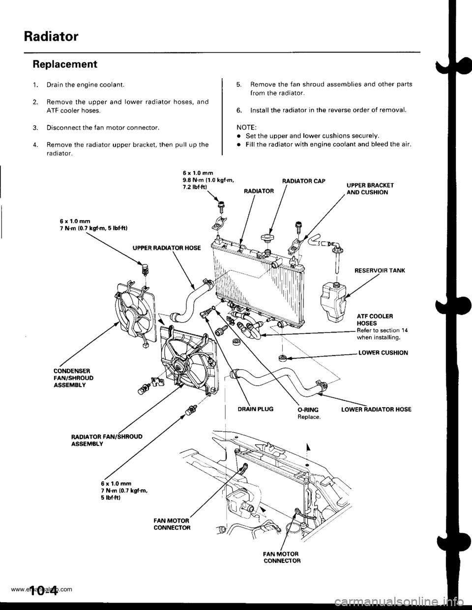
Drain the engine coolant.
Remove the upper and lower radiator hoses, and
ATF cooler hoses.
Disconnect the fan motor connector.
Remove the radiator upper bracket, then pull up the
raotalor,
5. Remove the fan shroud assemblies and other parts
from the radiator.
6. lnstall the radiator in the reverse order of removal.
NOTE:
. Set the upper and lower cushions securely.
. Fill the radiator with engine cooiant and bleed the air.
RADIATOR CAP
RADIATOR
6x1.0mm9.8 N.m 11.0 kgf.m,7.2 tbl.trl
6x1.0mm7 N.m (0.? kgd.m, 5 lbl.ftl
UPPER MDIATOR HOSE
Reler to section 14when installing.
DRAIN PLUG
LOWER CUSHION
LOWERTOR HOSE
RADIATORASSEMBLY
6x1.0mm7 N.|n 10.7 kgt.m,5 tbt.ftl
rriItriiii
10-4
www.emanualpro.com
Page 193 of 1395
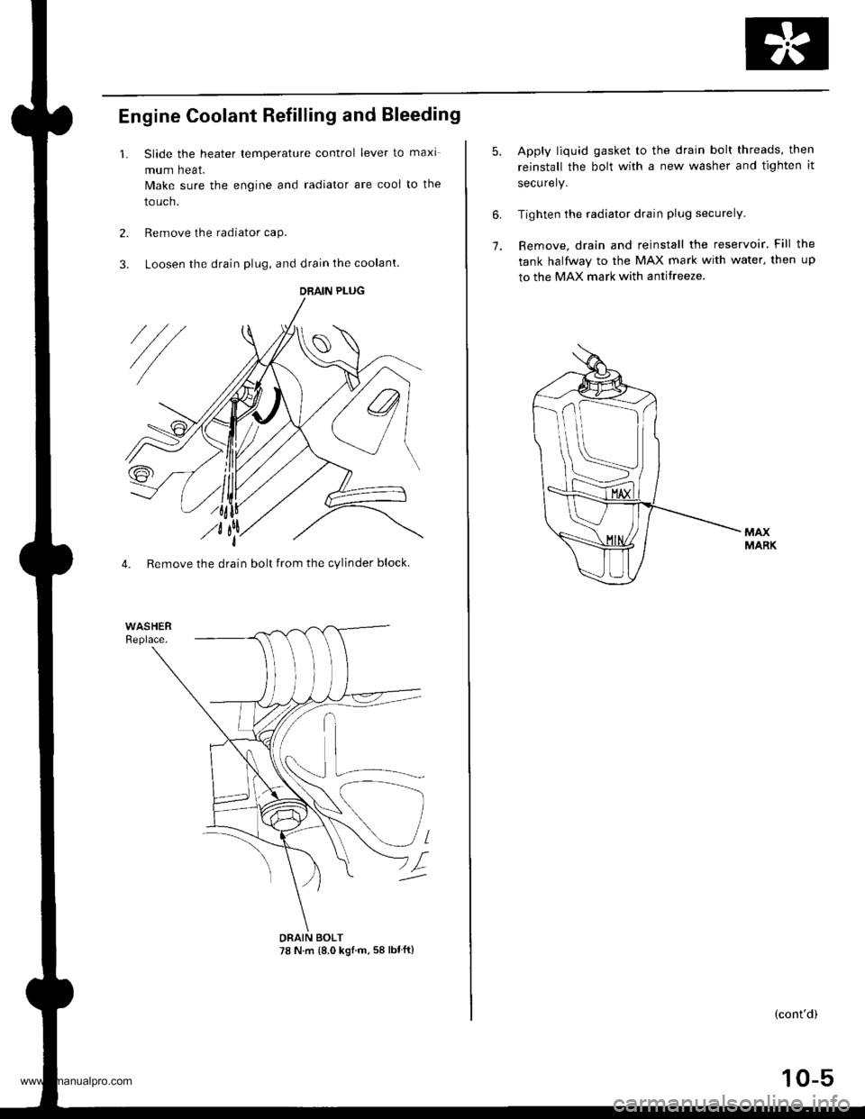
Engine Coolant Refilling and Bleeding
1. Slide the heater lemperature control lever to maxi
mum heat.
Make sure the engine and radiator are cooi to the
touch.
2. Remove the radiator caP.
3. Loosen the drain plug, and drain the coolant.
4. Remove the drain bolt from the cylinder block.
DRAIN PLUG
DRAIN BOLT78 N.m {8.0 ksl.m, 58 lbtft}
10-5
6.
7.
Apply liquid gasket to the drain bolt threads, then
reinstall the bolt with a new washer and tighten it
securely.
Tighten the radiator drain plug securely.
Remove, drain and reinstall the reservoir' Fill the
tank halfway to the MAX mark with water, then up
to the MAX mark with antitreeze.
(cont'd)
www.emanualpro.com
Page 442 of 1395
MaintenanceBack-up Light Switch
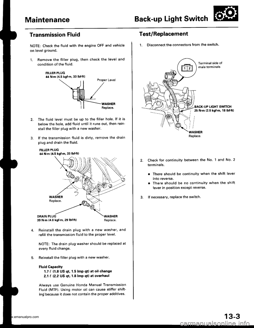
Transmission Fluid
NOTE: Check the fluid with the engine OFF and vehicle
on level ground.
1. Remove the filler plug. then check the level and
condition of the fluid.
FILLER PLUG44 N.m {4.5 kgf.m. 33 lbf ftl
ll
Ptopet Level
\--ril /
HllllllTl /
Hllllrlll /_rf-F{--rno."."
ll| | Replaco.
The fluid level must be up to the filler hole. lf it is
below the hole, add fluid until it runs out. then rein-
stall the tiller plug with a new washer.
lf the transmission fluid is diny, remove the drain
plug and drain the fluid.
FILLEB PLUGa,a N.m 14.5 kgf..n. 33 lbt'ftl
DRAIN PLUG39 N m (4.0 kgf.m, 29 lbf'ft)WASHERReplace.
Reinstall the drain plug with a new washer. and
refill the transmission fluid to the proper level.
NOTE: The drain plug washer should be replaced at
every fluid change.
Reinstall the filler plug with a new washer.
Fluid Capacity
1.7 / {1.8 US qt, 1.5 lmp qtl at oil change
2.1 ! 12.2 US qt, 1.A lmp qtl at overhaul
Alwavs use Genuine Honda Manual Transmission
Fluid (MTF). Using motor oil can cause stiffer shift-
ind because it does not contain the proper additives.
Test/Replacement
1. Disconnect the connectors from the switch.
Terminal side oImale lerminals
BACK.UP LIGHT SWTTCHr 25 N.m 12.5 kgt m, 18 lbf.ftl
WASHERReplace.
Check for continuity between the No. 1 and No. 2
terminals.
. There should be continuity when the shift lever
tnto reverse.
. There should be no continuity when the shift
lever in position except reverse,
lf necessary, replace the switch.
13-3
www.emanualpro.com
Page 444 of 1395
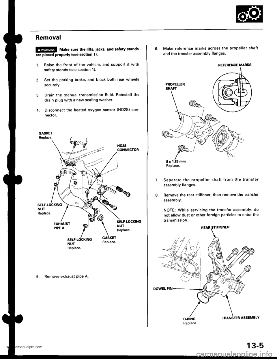
Removal
!@@ Make sure the lifts, i8cks. and safety stands
are placed properly {see section 1}.
1. Raise the front of the vehicle, and support it with
safety stands (see section 1).
2. Set the parking brake, and block both rear wheels
securely.
3. Drain the manual transmission fluid Reinstall the
drain plug with a new sealing washer.
4. Disconnect the heated oxygen sensor (HO2S) con-
nector.
SELF.L(rcKNGNUTReplace.
SELF-LOCKI'{GNUTReplac€.
5. Remove exhaust oipe A.
6. Make reference marks across the propeller shaft
and the transfer assembly flanges'
Separate the propeller shaft from the transfer
assembly flanges,
Remove the rear stiffener, then remove the transfer
assembly.
NOTE: While servicing the transfer assembly, do
not allow dust or other foreign particles to enter the
transmission.
7.
REFEREI{CE i'ARKS
Replace.
Replace.
13-5
www.emanualpro.com
Page 452 of 1395
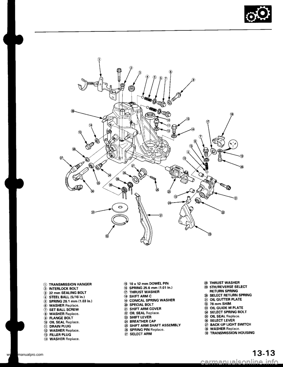
C) TRANSMISSION HANGER
O INTERLOCK BOLT
O 32 mm SEALING BOLT
@ STEEL BALL {5/16 in.)
€) SPRING 26.1 mm {1.03 in.l
@ wasHER Replace.
O sET BALL scREw
@ WASHER Replace.
€) FLANGE BOLT
@ oll SEAL Replace.
@ DRAIN PLUG
@ WASHER Replace.
@ FILLER PLUG
@ WASHER Replace.
(9 10 x 12 mm DOWEL PIN(D SPRING 25.6 mm 11.01 in.l
€' THRUST WASHER
@} SHIFT ARM C(3 CONICAL SPRING WASHER
@ SPECTAL BOLT
8] SHIFT ARM COVER
@ OIL SEAL Replace.
€! SHIFT LEVER
@I BREATHER CAP(2! SHIFT ARM SHAFT ASSEMBLY
@ SPRING PIN Replace.O SELECT ARM
€!} THRUST WASHER
@ sTH/REVERSE SELECTRETURN SPRING
@ SELECT RETURN SPRING
€) OIL GUTTER PLATE
@ 78 mm SHIM
@ OIL GUIOE M PLATE
@ SELECT SPRING BOLT
@ OIL SEAL Replace.
@ SELECT LEVER
O BACK.UP LIGHT SWITCH
@ WASHER Replace.OO TRANSMISSION HOUSING
13-13
www.emanualpro.com
Page 454 of 1395
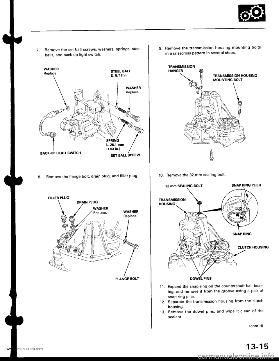
7. Remove the set ball screws, washers, springs, steel
balls. and back-uP light switch.
STEEL BALLD. 5/16 in
8. Remove the flange bolt. drain plug, and filler plug
DRAIN PLUG
WASHERReplace.
LIGHT SWITCH
FILLER PLUG
WASHERReplace.
FLANGE BOLT
9. Remove the transmission housing mounting bolts
in a crisscross pauern in several steps.
10. Remove the 32 mm sealing bolt
Expand the snap ring on the countershaft ball bear-
ing, and remove it from the groove using a pair of
snap ring plier.
Separate the transmission housing from the clutch
housing.
Remove the dowel pins, and wipe it clean of the
sealant.
'I t.
(cont'd)
13-15
www.emanualpro.com
Page 509 of 1395
Transmission Assembly
Reassembly lcont'd)
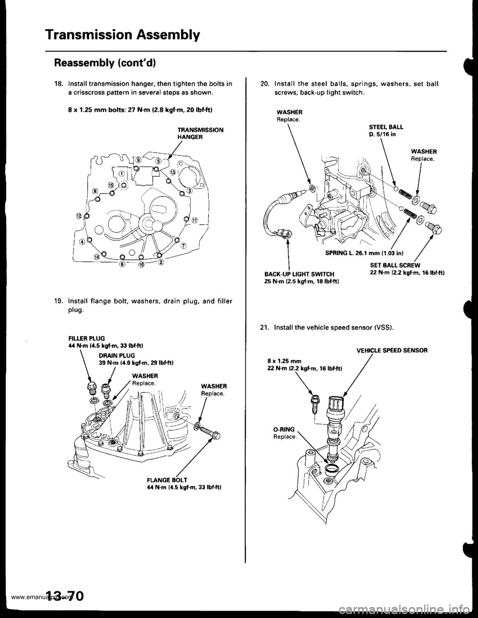
18. Installtransmission hanger, then tighten the bolts in
a crisscross pattern in several steps as shown.
8 x 1.25 mm bolis: 27 N.m 12.8 kgf.m,20 lbf'ft}
TRANSMISSIONHANGER
19.Install flange bolt,
plug.
washers, drain plug. and filler
FILLER PLUG4,r N.m (a.5 kgl.m,33lbtftl
DRAIN PLUG39 N.m {4.0 kg{.m,29lbtftl
WASHERReplace.WASHER
13-70
20. Install the steel balls, springs. washers, set ball
screws, back-up light switch.
WASHERReplace.
STEEL BALLD,5/16 in
21. Installthe vehicle speed sensor (VSS).
VEHICI."E SPEED SENSOR
8 x 1.25 mm22 N.m 12.2 kgl.m, 16 lbt.ftl
SPRING L.26.1 mm 11.03 inl
www.emanualpro.com