check engine HONDA CR-V 2000 RD1-RD3 / 1.G Workshop Manual
[x] Cancel search | Manufacturer: HONDA, Model Year: 2000, Model line: CR-V, Model: HONDA CR-V 2000 RD1-RD3 / 1.GPages: 1395, PDF Size: 35.62 MB
Page 401 of 1395
Emission Control System
System Description
The emission control system includes, a Three Way
Catalytic Converter {TWC), Positive Crankcase Ventilation
(PCV) svstem and Evaporative Emission (€VAP) Control
system. The emission control system is designed to meet
federal and state emission standards.
Tailpipe Emission
Inspsction
!@ Do not smoke during this procsdura. Keep
any open tlame away from your work area.
1. Start the engine. Hold the engine at 3,000 rpm with
no load (in Park or neutral) until the radiator fan
comes on, then let it idle,
Connect a tachometer.
Check and, if necessary, adjust the idle speed, (see
page 11-169, 170).
Warm up and calibrate the CO meter according to the
meter manufacturer's instructions.
Check idle CO with the headlights, heater blower, rear
window defogger, cooling fan, and air conditioner off.
(Canada) Pull the parking brake lever up. Start the
engine, then check that the headlights are off.
CO meter should indicate 0.1% maximum.
4.
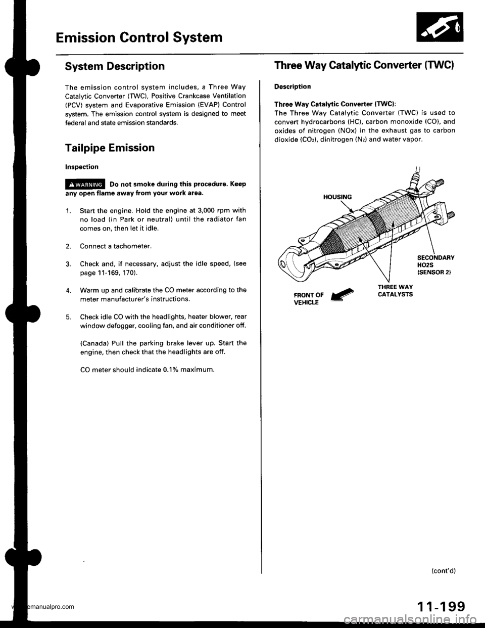
Three Way Catalytic Converter (TWCI
DsscriDtion
Three Way Catalytic Convertsr lTwcl:
The Three wav Catalvtic Converter (TWC) is used to
convert hydrocarbons (HC), carbon monoxide (CO), and
oxides of nitrogen (NOx) in the exhaust gas to carbon
dioxide (COr), dinitrogen (Nr) and water vapor,
{cont'd)
1 1-199
www.emanualpro.com
Page 402 of 1395
Emission Control System
Three Way Catalytic Converter {TWCI (cont'd}
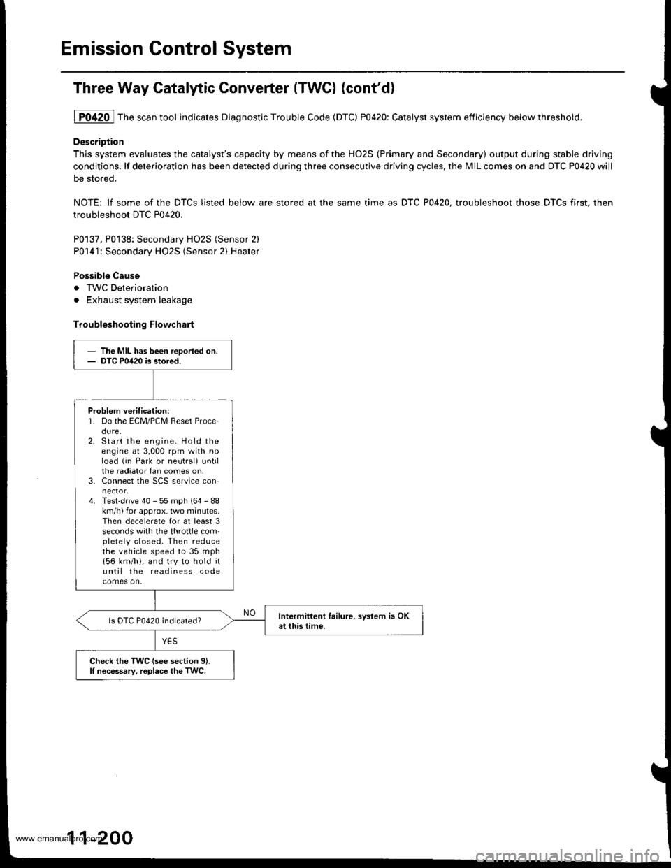
1P0420 Thescantool indicates Diagnostic Trouble Code (DTC) P0420: Catalyst system efficiency belowthreshold.
DescriDtion
This system evaluates the catalyst's capacity by means of the HO2S (Primary and Secondary) output during stable driving
conditions. lf deterioration has been detected during three consecutive driving cycles, the MIL comes on and DTC P0420 will
be stored.
NOTE: lf some of the DTCS listed below are stored at the same time as DTC P0420, troubleshoot those DTCS first. then
troubleshoot DTC P0420.
P0137, P0138: Secondary HO2S (Sensor 2)
P0141: Secondary HO2S (Sensor 2) Heater
Possible Cause
. IWC Deterioration
. Exhaust system leakage
Troubleshooting Flowchart
- The MIL has been reDoried on.- DTC P0420 is stored.
Problem verification:1. Do the ECM/PCM Reset Procedure,2. Start the engine. Hold theengine at 3,000 rpm with noload (in Park or neutrali untilthe radiator fan comes on.3. Connect the SCS service connector.4. Test-drive 40 - 55 mph (64 - 88km/h) for approx. lwo minutes.Then decelerate for at least 3seconds with the throftle completely closed. Then reducethe vehicle speed to 35 mph
156 km/h), and try to hold ituntil the readiness code
Intermittent tailure. system is OKat this time.ls DTC P0420 indicated?
Check the TWC (see section 9).lI nocessary, replace the TwC.
11-200
www.emanualpro.com
Page 403 of 1395
Positive Grankcase Ventilation (PGVI System
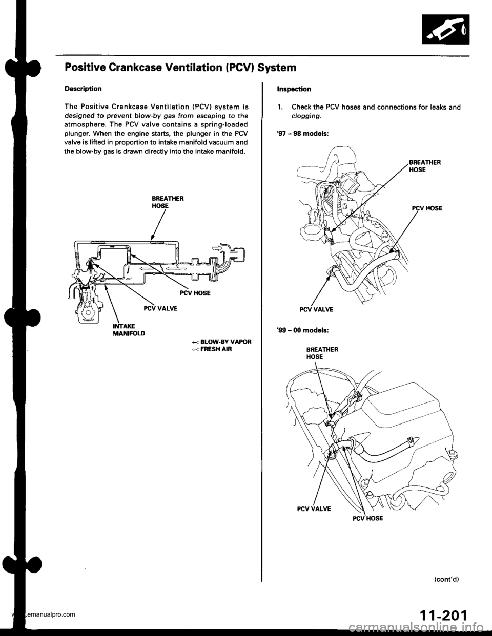
Description
The Positive Crankcase Ventilation (PCV) svstem is
designed to prevent blow-by gas from escaping to the
atmosphere. The PCV valve contains a spring-loaded
plunger, When the engine starts, the plunger in the PCV
valve is lifted in proportion to intake manitold vacuum and
the blow-by gas is drawn directly into the intake manifold.
-: BLOW.BY VAPOR-: FRESH AIR
i/lAlrllFOLD
Inspoction
1. Check the PCV hoses and connections for leaks and
clogging.
'97 - 98 models:
'99 - (X) models:
BREATHERHOSE
(cont'd)
11-201
www.emanualpro.com
Page 407 of 1395

'97 model:
The scan tool indicates Diagnostic Trouble Code (DTC) P0441: Evaporative Emission (EVAP) control system
insufficient purge flow.
Description
By monitoring the purge line vacuum with the MAP sensor, the PCM can detect insufficient EVAP control system purge
flow.
Possiblo Cause
. EVAP Purge Control Solenoid Valve
. EVAP Purge Control Solenoid Valve Circuit
. EVAP Control Canister
. Vacuum Lines
. PCM
Troubleshooting Flowchart
EVAP PURGE CONTROL
SO1TNOID VALVE 2P
CoNNECTOR (C108)
(v)
YL
Wire side of female
termrnals
(cont'd)
11-205
Th€ MIL has b€en reooited on.DTC P0441 is .tored.
Problem verificationl1. Start the engine. Hold theengine at 3,000 rpm with noload (in Park or neut.al) untilthe radiator fan comes on.2. Do the PCM Reset Procedure.3. Connect the SCS service con-nector,4. Test drive under following con'ditions on the road.- without any electrical load- Transmission in @ or @position- Engine speed between1 ,2OO - 2,4OO rpfi.- Decelerate from 50 mph (80
km/h)to 15 mph (24 km/h)Intermittent trilure, sydern is OKat this time. Check for Door con-nections or loose wir€3 at C108
IEVAP purge control solonoidvalvol .nd at the PCM.
ls DTC P0441 indicated?
Check tor an open in the wire (lcl
linel:1. Turn the ignition switch OFF.2. Disconnect the EVAP purge
control solenoid valve 2P con-nector.3. Turn the ignition switch ON (ll).
4. Measure voltage between bodyground and the EVAP purge
control solenoid valve 2P con-nector terminal No. '1,
R€pafu open in thc wir6 b€tw€enthG EVAP purge control solenoidvalve and the No. 15 ALTEBNA-TOR SP SENSOR (7.5 A)fuse.
ls there batlery voltage?
(To page 11'206)
www.emanualpro.com
Page 409 of 1395
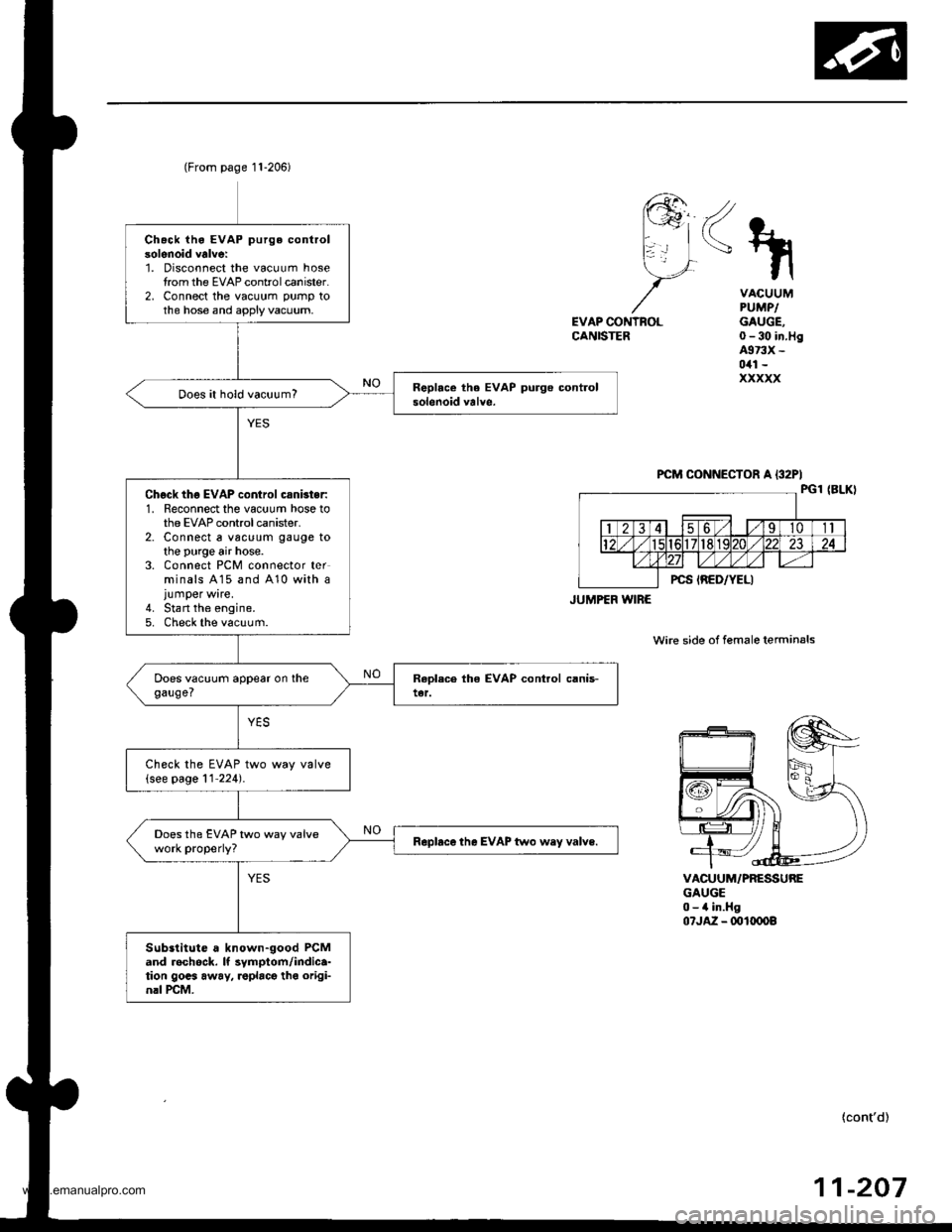
Chack iho EVAP purge controlsolenoid valve:1. Disconnect the vacuum hosetrom the EVAP controlcanister.2, Connect the vacuum pump tothe hose and apply vacuum,
Does it hold vacuum?
Chgck thg EVAP control csnbter:1. Reconnect the vacuum hose tothe EVAP control canister.2. Connect a vac!um gauge tothe purge air hose.3. Connect PCM connector terminals A15 and 410 with ajumper wire.4. Stan the engine.5. Check the vacuum.
Check the EVAP two way valve(see page 11'224).
Does the EVAP two way valvework properly?Rapbce the EVAP two wey valve.
Substitute a known-good PCMand rechock. It symptom/indica-tion gocs away, roplacg tho origi-nrl rcM.
(From page 11-206)
JUMPEF WIRE
<\
EVAP CONTNOLCANISTER
VACUUMPUMPIGAUGE,0-30 in.Hg4973X -
0il1 -
xxxxx
VACUUM/PRESSUREGAUGE0-4 in.Hg07JA2 - ml(x)o8
wire side of female terminals
{cont'd)
-20711
www.emanualpro.com
Page 425 of 1395
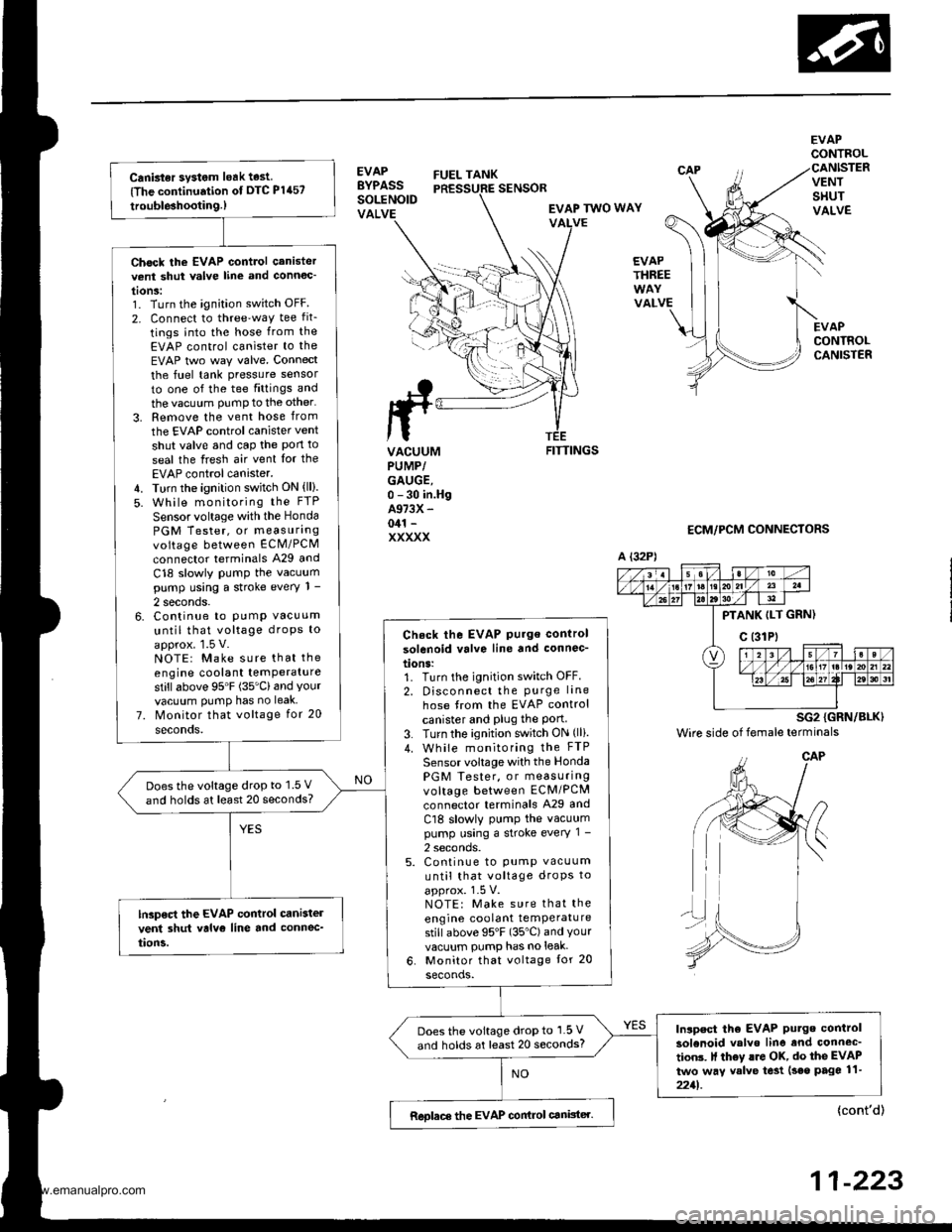
Canbter system leak test
{The continuation of DTC P1457
trouble3hootin9.)
Chock the EVAP control canistervent shut valve line and connoc'
tonS:1. Turn the ignition switch OFF
2. Connect to three'way tee fit_
tings into the hose from the
EVAP control canister to the
EVAP two way valve. Connect
the fuel tank pressure sensor
to one of the tee fittings and
the vacuum PumP to the other'
3. Remove the vent hose from
the EVAP control canister vent
shut valve and cap the Pon to
seal the fresh air vent Ior the
EVAP control canister.4. Turn the ignition switch ON (ll).
5. While monitoring the FTP
Sensor voltage with the Honda
PGM Tester, or measurangvoltage between ECM/PCM
connector terminals A29 and
C18 slowly PumP the vacuumpump using a stroke every 1 -
2 seconds.6. Continue to PumP vacuum
until that voltage droPs to
approx. 1.5 V.NOTE: Make sure that the
engine coolant temPeraturestillabove 95'F (35'Cland Yourvacuum PumP has no leak
7. Monitor that voltage for 20
seconds.
Check the EVAP Pu.ge control
solenoid valve line and connec-
tions:1. Turn the ignition switch OFF.
2. Disconnect the Purge lane
hose from the EVAP control
canister and Plug the Port3. Turn the ignition switch ON (lli.
4. While monitoring the FTP
Sensor voltage with the Honda
PGM Tester, or measuringvoltage between ECM/PCM
connector terminals A29 and
Cl8 slowly PumP the vacuumpump using a stroke every 1 -
2 seconds.5. Continue to pump vacuum
until that voltage droPs to
approx. 1-5 V.NOTE: Make sure that the
engine coolant temPeraturestill above 95'F (35"C) and Yourvacuum pump has no leak-
6. Monitor that voltage tor 20
seconds.
Doesthe voltage drop to 1.5 V
and holds at least 20 seconds?
lGp€ct the EVAP control cani3tel
vent 3hut valvo line and connec_
tion5.
Inlpect tho EVAP Putge control
solenoid valvo line and connec'
tion3. It th6y lro OK, do the EVAP
two way valve te3t (seo page 11-
2211.
Does the voltage drop to 1.5 V
and holds at least 20 seconds?
Reolace the EVAP conirol canister.
EVAPBYPASSSOLENOIDVALVE
FUEL TANK
EVAPCONTROL
VENTSHUTVALVE
EVAPCONTROLCANISTER
SENSOR
EVAP TWO WAYVALVE
EVAPTHREE
VALVE
ttrrL
ta
VACUUMPUMP/GAUGE,0 - 30 in.HgA973X -
041 -
XXXXX
FITTINGS
ECM/PCM CONNECTORS
A {32P)
PTANK ILT GRN)
c (31Pt
SG2 {GRN/BLK)
Wire side of female terminals
{cont'd)
11-223
www.emanualpro.com
Page 431 of 1395
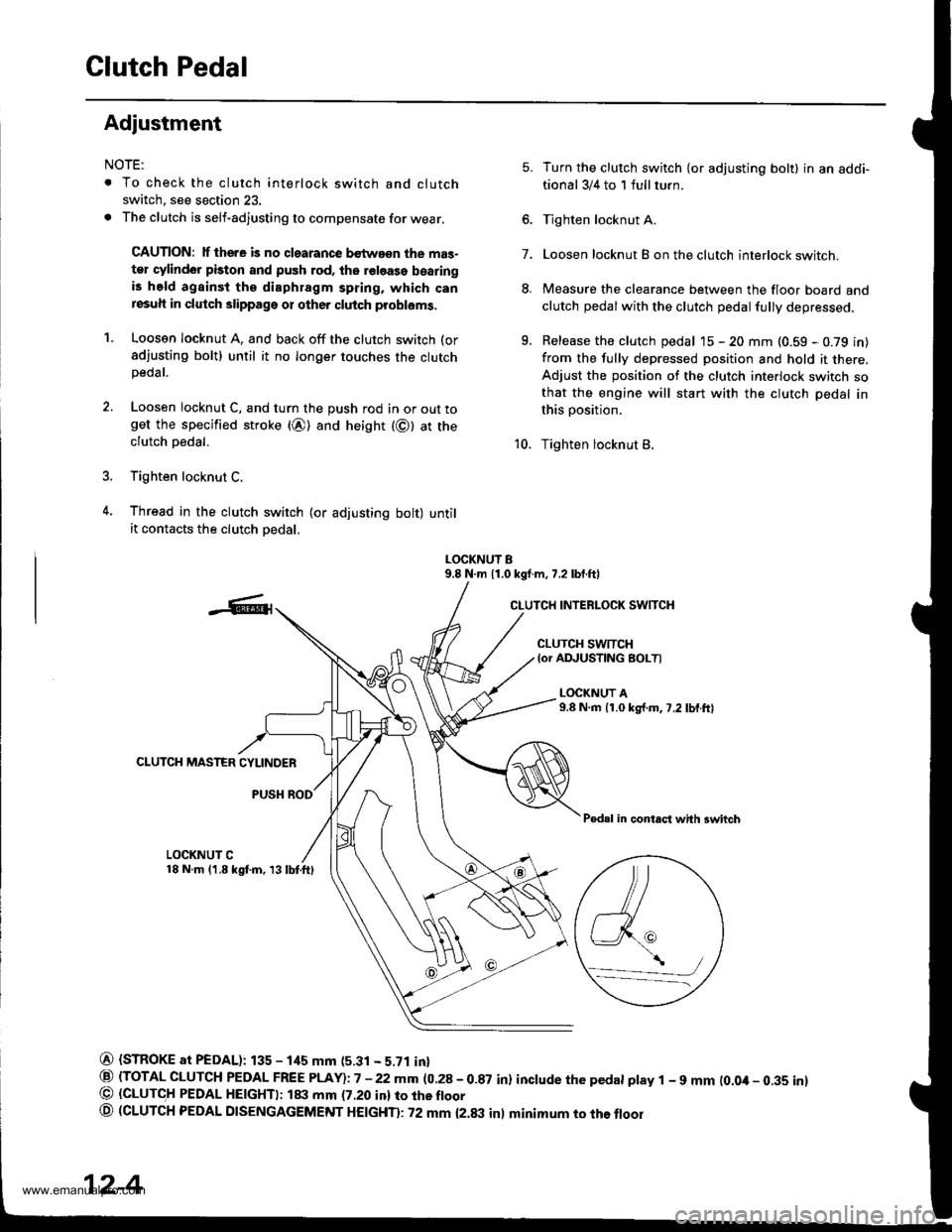
Clutch Pedal
Adiustment
NOTE:
. To check the clutch interlock switch and clutch
switch, see section 23.
. The clutch is self-adjusting to compensate for wear.
CAUTION: lf there is no clearance bstwa€n the mas-
ter cylinder piston and push rod, ths roloase bearingis held againsi the diaphragm spring, which canresuh in clutch slippage or other clutch probloms.
1. Loosen locknut A, and back off the clutch switch (or
sdjusting bolt) until it no longer touches the clutchpeoar.
2. Loosen locknut C, and turn the push rod in or out toget the specified stroke (@) and height (@) at theclutch oedal.
3. Tighten locknut C.
4. Thread in the clutch swirch (or adjusting bolt) untilit contacts the clutch oedal.
7.
5.
8.
q
Turn the clutch switch {or adjusting bolt} in an addi-
tional 3/4 to 1 full turn.
Tighten locknut A.
Loosen locknut B on the clutch interlock switch.
Measure the clearance between the floor board and
clutch pedalwith the clutch pedal fully depressed.
Release the clutch pedal 15 - 20 mm (0.59 - 0.79 in)
from the fully depressed position and hold it there,Adjust the position of the clutch interlock switch sothat the engine will start with the clutch pedal in
this position.
Tighten locknut B.10.
LOCKNUT B9.8 N.m 11.0 kgf.m, 7.2 lbf.ftl
CLUTCH INTERLOCK SWITCH
CLUTCH SWTTCH{or ADJUSTING BOLTI
L(rcKNUT A9.8 N.m {1.0 kg{.m,7.2 lbf.ftl
CLUTCH MASTER CYLINDER
PUSH ROD
Pedal in contact with swhch
LOCKNUT C18 N.m (1.8 kgf.m, 13lbtftl
@ {STROKE at PEDAL): 135 - 1its mm (5.31 - 5.71 in}
@ (TOTAL CLUTCH PEDAL FREE PLAY)i7 -22mm (0.28-0.87 in) inctude the pedat ptay 1 - 9 mm (0.0it- 0.35 inl@ (GLUTC,H PEDAL HE|GHTI: ltxt mm (7.20 inl ro rhe ftoor
o (CLUTCH PEDAL DTSENGAGEMENT HEtcHTl: 72 mm {2.txt inl minimum to the floor
\,/a_-_--/
12-4
www.emanualpro.com
Page 434 of 1395
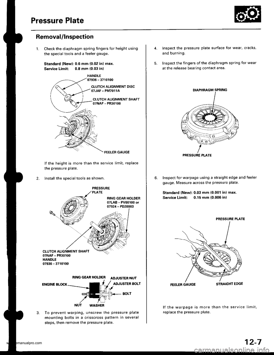
Pressure Plate
Removal/lnspection
1.Check the diaphragm spring fingers for height using
the special tools and a feeler gauge.
Standard lNewl: 0.6 mm {0.02 in) max.
Service Limit: 0.8 mm (0.03 in)
HANDLE07936 - 3710100
CLUTCH ALIGNMENT DISCOTJAF - PM7O11A
CI.UTCH ALIGNMENT SHAFT07NAF - PR30100
FEELER GAUGE
lf the height is more than
the pressure Plate.
the service limit, replace
2. lnstall the sDeciallools as shown.
RING GEAR HOLDER ADJUSTER NUT
ENGINE BLOCKADJUSTER BOLT
BOLT
NUT WASHER
To prevent warping, unscrew the pressure plate
mounting bolts in a crisscross pattern in several
steps. then remove the pressure plate.
4. Inspect the pressure plate surface for wear, cracks,
and burning.
5. Inspect the fingers of the diaphragm spring for wear
at the release bearing contact area.
Inspect for warpage using a straight edge and feeler
gauge. Measure across the pressure plate.
Standard lNew): 0.03 mm 10.001 in) max.
Service Limit: 0.15 mm (0.006 inl
6.
FEELER GAUGE
lf the warpage is more than the service limit,
replace the pressure plate.
PRESSURE PLATE
PRESSURE PLATE
12-7
www.emanualpro.com
Page 436 of 1395
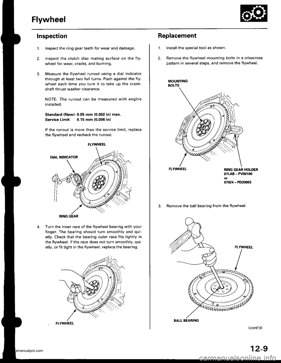
Flywheel
Inspection
2.
3.
Llnspect the ring gear teeth for wear and damage.
Inspect the clutch disc mating surface on the fly-
wheel for wear, cracks, and burning
Measure the flywheel runout using a dial indicator
through at least two full turns. Push against the fly-
wheel each time you turn it to take up the crank-
shaft thrust washer clearance.
NOTE: The runout can be measured with engine
installed.
Standard (Newl: 0.05 mm (0.002 in) max.
Service Limit: 0.15 mm {0.006 inl
lf the runout is more than the service limit, replace
the flywheel and recheck the runout
Turn the inner race ot the flywheel bearing with your
finger. The bearing should turn smoothly and qui-
etly. Check that the bearing outer race fits tightly in
the tlywheel. lf the race does not turn smoothly, qui-
etly, or fit tight in the flywheel, replace the bearing.
FLYWHEEL
RING GEAR
FLYWHEEL
L
2.
Replacement
Installthe special tool as shown.
Remove the flywheel mounting bolts in a crisscross
pattern in several steps, and remove the flywheel.
MOUNNNGBOLTS
FLYWHEEL
(cont'd)
12-9
RING GEAR HOLDER07LAB - PV00r00ol07924 - PD20003
3. Remove the ball bearing from the flywheel.
BALL BEARING
www.emanualpro.com
Page 442 of 1395
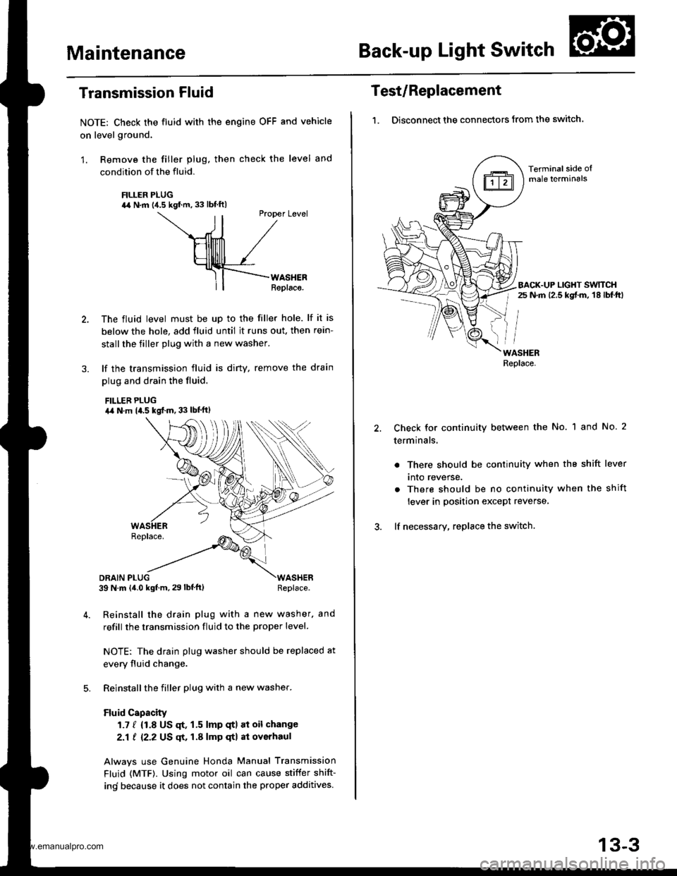
MaintenanceBack-up Light Switch
Transmission Fluid
NOTE: Check the fluid with the engine OFF and vehicle
on level ground.
1. Remove the filler plug. then check the level and
condition of the fluid.
FILLER PLUG44 N.m {4.5 kgf.m. 33 lbf ftl
ll
Ptopet Level
\--ril /
HllllllTl /
Hllllrlll /_rf-F{--rno."."
ll| | Replaco.
The fluid level must be up to the filler hole. lf it is
below the hole, add fluid until it runs out. then rein-
stall the tiller plug with a new washer.
lf the transmission fluid is diny, remove the drain
plug and drain the fluid.
FILLEB PLUGa,a N.m 14.5 kgf..n. 33 lbt'ftl
DRAIN PLUG39 N m (4.0 kgf.m, 29 lbf'ft)WASHERReplace.
Reinstall the drain plug with a new washer. and
refill the transmission fluid to the proper level.
NOTE: The drain plug washer should be replaced at
every fluid change.
Reinstall the filler plug with a new washer.
Fluid Capacity
1.7 / {1.8 US qt, 1.5 lmp qtl at oil change
2.1 ! 12.2 US qt, 1.A lmp qtl at overhaul
Alwavs use Genuine Honda Manual Transmission
Fluid (MTF). Using motor oil can cause stiffer shift-
ind because it does not contain the proper additives.
Test/Replacement
1. Disconnect the connectors from the switch.
Terminal side oImale lerminals
BACK.UP LIGHT SWTTCHr 25 N.m 12.5 kgt m, 18 lbf.ftl
WASHERReplace.
Check for continuity between the No. 1 and No. 2
terminals.
. There should be continuity when the shift lever
tnto reverse.
. There should be no continuity when the shift
lever in position except reverse,
lf necessary, replace the switch.
13-3
www.emanualpro.com