Valve clea HONDA CR-V 2000 RD1-RD3 / 1.G User Guide
[x] Cancel search | Manufacturer: HONDA, Model Year: 2000, Model line: CR-V, Model: HONDA CR-V 2000 RD1-RD3 / 1.GPages: 1395, PDF Size: 35.62 MB
Page 140 of 1395
Cylinder Head
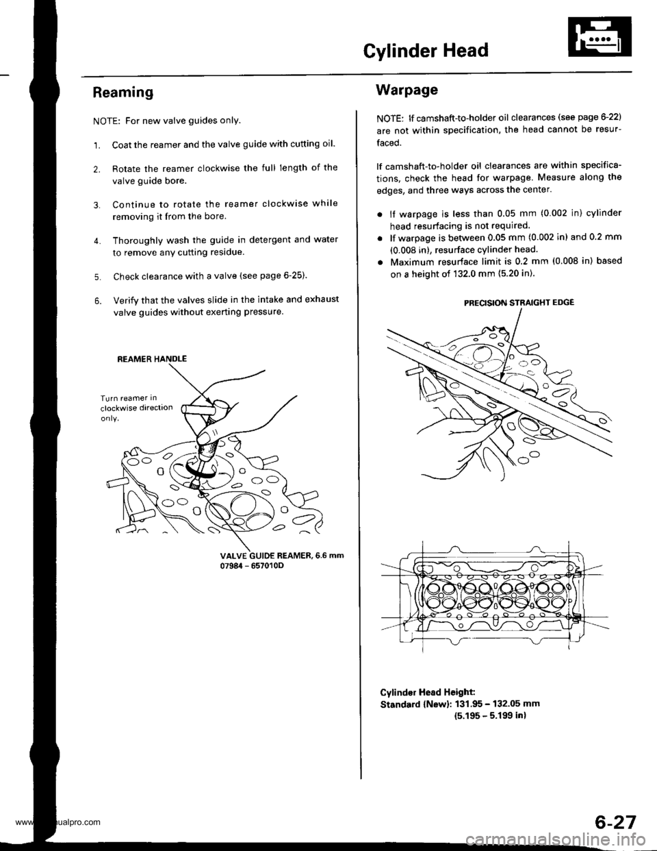
Reaming
NOTE: For new valve guides only.
1. Coat the reamer and the valve guide with cutting oil.
2. Rotate the reamer clockwise the full length of the
valve guide bore.
Continue to rotate the reamer clockwise while
removing it from the bore.
Thoroughly wash the guide in detergent and water
to remove anY cutting residue.
Check clearance with a valve (see page 6-25).
Verify that the valves slide in the intake and exhaust
valve guides without exerting pressure.
3.
4.
5.
6.
vALvE GUIDE REAMER,6.6 mm0798i1 - 657010O
REAMER HANDLE
e
Warpage
NOTE: lf camshaft-to-holder oil clearances (see page G22)
are not within specification, the head cannot be resur-
faced.
lf camshaft-to-holder oil clearances are within specifica-
tions, check the head for warpage. Measure along the
edges, and three ways across the center.
. if warpage is less than 0.05 mm (0.002 in) cylinder
head resurfacing is not required
lf warpage is between 0.05 mm (0.002 in) and 0.2 mm
(0.008 in), resurface cylinder head.
Maximum resurface limit is 0.2 mm (0.008 in) based
on a height of 132.0 mm (5.20 in).
Cylind€r Hesd Height:
Standard {New}: 131.95 - 132.05 mm
15.195 - 5.199 inl
PRECISION STRAIGHT EDGE
6-27
www.emanualpro.com
Page 144 of 1395
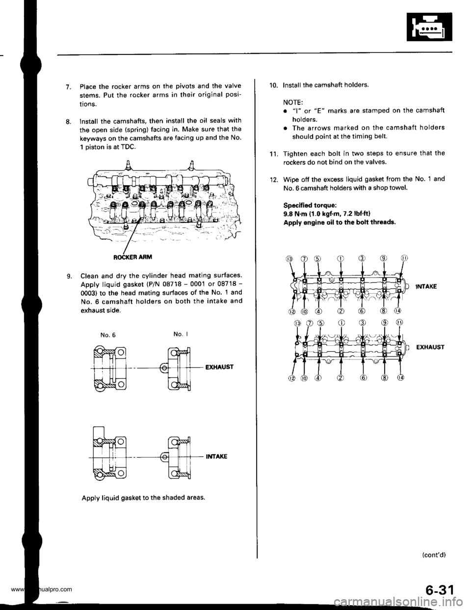
7.Place the rocker arms on the pivots and the valve
stems. Put the rocker arms in their original posi-
lrons.
lnstall the camshafts, then install the oil seals with
the open side (spring) facing in. Make sure that the
keyways on the camshafts are facing up and the No.
1 piston is at TDC.
Clean and dry the cylinder head mating surfaces.
Apply liquid gasket (P/N 08718 - 0001 or 08718 -
0OO3) to the head mating surfaces of the No. 1 and
No. 6 camshaft holders on both the intake and
exhaust side.
L
No. I
EXHAUST
II{TAKE
Apply liquid gasket to th€ shaded areas.
't't,
'10. lnstall the camshaft holders.
NOTE:
o "1" or "E' marks are stamped on the camshaft
holders.
. The arrows marked on the camshaft holders
should point at the timing belt.
Tighten each bolt in two steps to ensure that the
rockers do not bind on the valves.
Wipe off the excess liquid gasket from the No. 1 and
No. 6 camshaft holders with a shop towel,
Specified torque:
9.8 N.m (1.0 kgf.m, 7.2 lbf.ft)
Apply engine oil to the bolt ihreads.
I?,ITAKE
EXHAUST
(cont'd)
6-31
www.emanualpro.com
Page 145 of 1395

Cylinder Head
Installation (cont'dl
'13. Align the marks on the cylinder head plug to thecylinder head upper surface, then install the cylin
der head plug in the end of the cylinder head.
CYLINOER HEADPLUGReplace.
lnstallthe back cover.
To set the camshafts at TDC position for the No. lpiston, align the holes in the camshafts with theholes in the No. l camshaft holders and insert 5.0mm pin punches in the holes. Install the keys into
the camshaft grooves.
37 N m (3.8 *gl.m, 27 lbt.tr)
9.8 N.m (1.0 kgtm,7.2|hrftl
Push the camshaft pulleys onto the camshafts. thentighten the retaining bolts to the torque specified.
6-32
14.
KEYS
I x 1.25 mm
6x1.0mm
Install the timing belt (see page 6-1 1).
Adjust the valve clearance (see page 6-3).
Thoroughly clean the head cover gasket and thegroove.
lnstall the head cover gasket in the groove of thecylinder head cover. Seat the head cover gasket in
the recesses for the camshaft first, then work it into
the groove around the outside edges. Make sure thehead cover gasket is seated securely in the corners
of the recesses with no gap.
17.
'18.
19.
www.emanualpro.com
Page 204 of 1395

Fuel and Emissions
Special Tools ...................... 11-2
Component Locations
lndex ...................... ....,.... 11-3
Svstem Description
Vacuum Connections ...........,....,.,................. 1 1-9
Electrical Connections ................................... 1 1-15
System Connectors .,.,,.,............................,.,. 1 1-36
Troubleshooting
Troubleshooting Procedures,.,..................... 11-60
Engine Control Module/Powertrain ConttolModule Terminal Arrangement .............., 11-67
Diagnostic Trouble Code Chart .................... 1 t-75
How to Read Flowcharts .......,.....,.,............... I 1-79
PGM-Fl System
System Description .................,.,.,,,............... 1 1-80
Troubleshooting Flowcharts
Engine Control Module/PowertrainControl Module ........11-52
Manifold Absolute Pressure Sensor ............. 11-90
Intake Air Temperature Sensor .................... 1 1-95
Engine Coolant Temperature Sensor .,..,.,.... 1 1-99
Throttle Position Sensor ...........,.....,.,.,..,...... I 1'103
Primary Heated Orygen Sensor (Sensor 1) ... 11-110
Secondary Heated Oxygen Sensor{Sensor 2l .................. 1 1-117
Heated Oxygen Sensor Heater ..................... 11-121
Fuef Supply System ......11-124
Random Misfire ,....,.,..... 11-126
Mistire Detected in One Cylinder .....-........... 11-128
Knock Sensor ................ 11-130
CKP/TDC/CYP Sensor .................................... 1 1-131
Vehicle Speed Sensor ...............................,.... 1 1-135
Barometric Pressure Sensor .....,...,...,.,,........ 1 1-137
Electrical Load Detector ...,.,.......................... 1 1-138
CKF Sensor ................,.,, '11-112
ECM/PCM lnternaf Circuit ............................. 11'117
HO2S Replacement .,.,.,. 11-148
ldle Control System
System Description ............ 11-149
Troubleshooting Flowcharts
ldle Control System ...... 11-150
fdle Air Control Valve ......................,............. 11-152
Air Conditioning Signal ................................. I 1-155
Alternator FR Signal ...................................... 1 1-159
Starter Switch Si9na1 .................................... t l-161
Power Steering Pressure Switch Signal ...... 11-162
Brake Switch Si9na1 ...................................... 11-166
Fast ldle Thermo Valve .,.,.............................,.,.,. 11-168
ldle speed setting .............. 11-169
Fuel Supply System
Fuel Lines ............................ 11-171
Fuef Tube/Ouick-Conneci Fittings ..................... 11 -175
System Description ............ 11-178
Fuel Pressurg ...................... 11-178
Fuel Iniectors ................,..... 11-179
Fuel Pressure Re9u1ator .............................,.,...., f 1-181
Fuef Fifter ....,.,.,.,,,,.,............11-142
Fuel Pump ........................... 11-183
Fuel Gauge .......................... 11-184
Fuel Gauge Sending Unit ................................... I 1-185
Low Fuel Indicator System ...........,.,..,............... 1 1-185
PGM-FI Main Relay ............. 11-187
Fue|Tank................ ............. 11-191
Intake Air System
System Description ............ 11-193
Air Cleanel ,.,.,..................... 11-194
Throttle Cable ..................... 11-194
Throttle Body........ .............. 11-196
Emission Control System
System D$cription ...,....,.,. 11-199
Tailpipe Emission ............... 11-199
Three Way Catalytic Converter ..................,.,...,, 11-199
Positive Crankcase Ventilation System .,.,,,,.,.., 11-2O1
Evaporative Emission Controls .........,.,.,............ 11-203
www.emanualpro.com
Page 208 of 1395
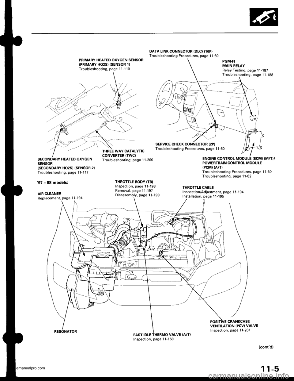
DATA LINK CONNECTOR {DLC) I16P}Troubleshooting Procedures, page 1 1'60PRIMARY HEATED OXYGEN SENSOR
{PRIMARY HO2SI {SENSOR 1)Troubleshooling, page 11 110
SECONDARY HEATED OXYGENSENSOR{SECONDARY HO2S) {SENSOR 2)Troubleshooting, page 1 1-1 17
'97 - 98 models:
AIR CLEANERReplacement, page 1 1'194
Troubleshooting, page 1 'l -200
THROTTLE BODY (TB)Inspection, page 11 196Removal, page 11-197Disassembly, page 1 1-'198
POWERTRAIN CONTROL MODULE(PCM) (A/TI
Troubleshooting Procedures, page 1 1-60Troubleshooting. page 1 1'82
THROTTLE CABLEInspection/Adjustment, page 1 1-1 94Installation, page 11- 195
VENTILATION (PCV) VALVEInspection, page 1 1-201FAST IDLEVALVE (A/T}
(cont'd)
1 1-5
PGM-FIMAIN RELAYRelay Testing, page 11-l87Troubleshooting. page 1'1 188
SERVICE CHECK CONNECTOR {2PITroubleshooting Procedures, page 1 1-60
,a'=_-_
WAY CATALYTIC
Inspection, page 1 1-168
www.emanualpro.com
Page 209 of 1395
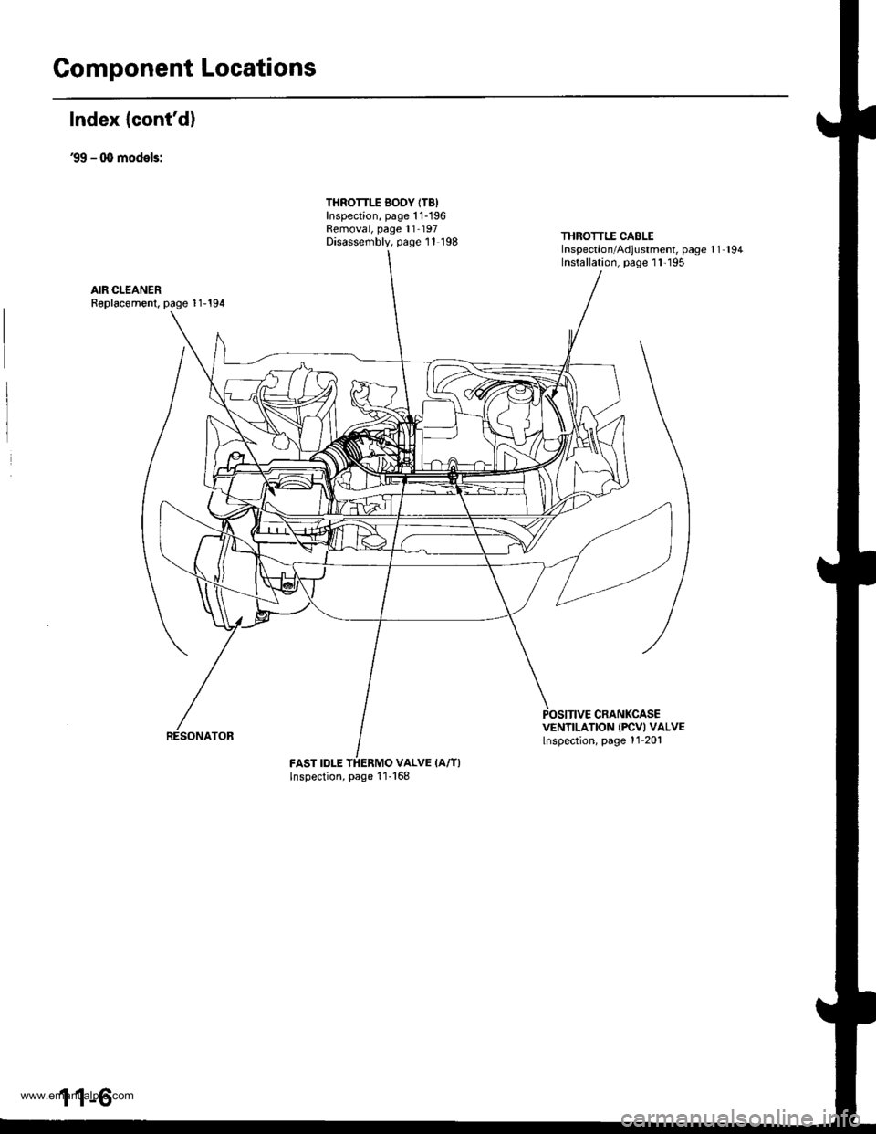
Component Locations
Index {cont'd)
39 - q, models:
THROTTLE BODY ITB)Inspection, page 1 1-196Removal, page 11- 197Disassembly, page 11 198THROTTLE CABLEInspectaon/Adjustment, page 1 1 194Installation, page I l'195
AIR CLEANERR€placomenl, page 1 1-194
CRANKCASEVENTILATION IFCVI VALVElnspection, page 11 201
FAST IDLE THERMO VALVE IA/T)Inspection, page 11'168
1 1-6
www.emanualpro.com
Page 213 of 1395
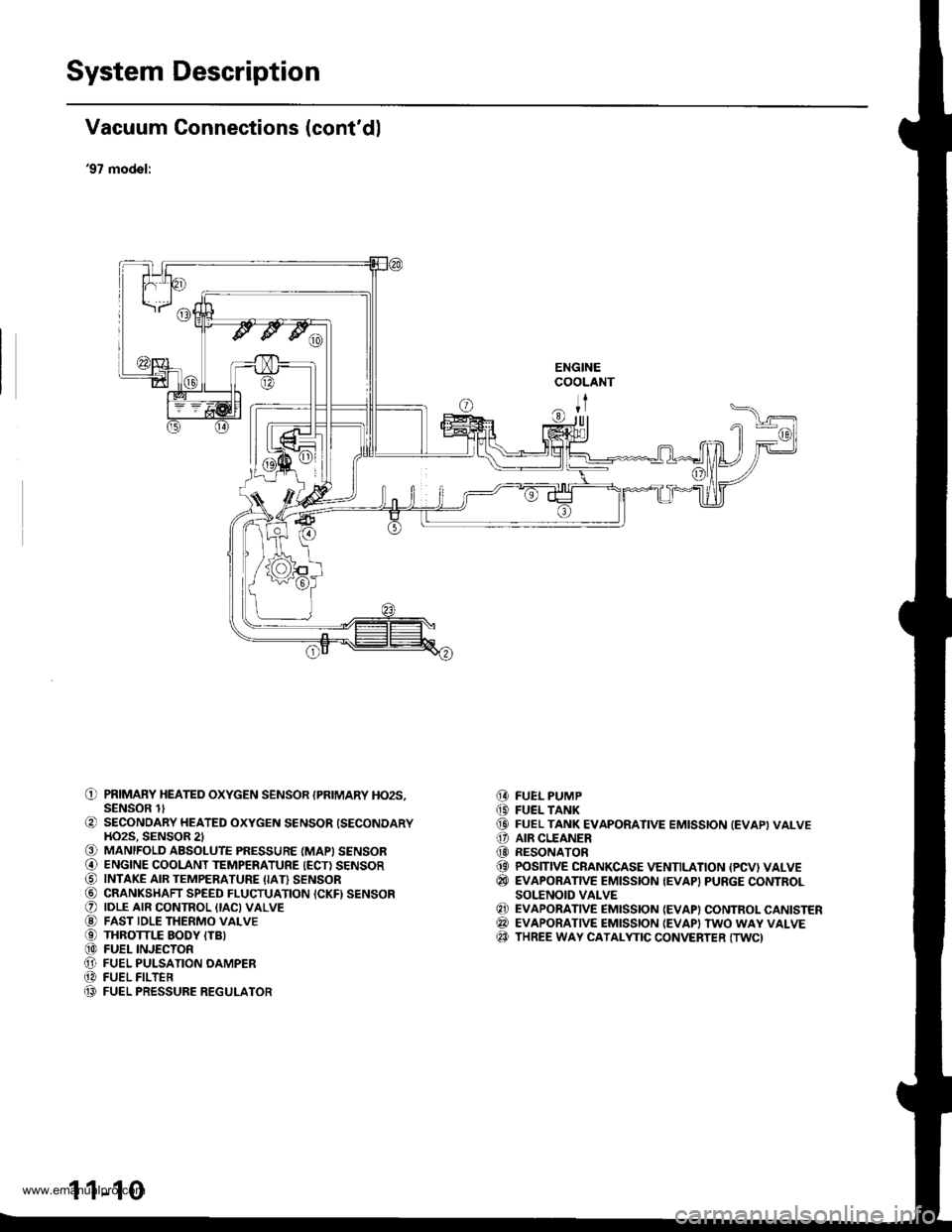
System Description
Vacuum Connections (cont'dl
'97 model:
ENGINECOOLANT
ITr|ll
O PRIMARY HEATED oxYGEN sENsoR {PRIMARY Ho2s,SENSOR lt
O SECONDARY HEATED oxYGEN sENsoR {SECoNDARYHO2S. SENSOR 2l€) MANIFOLD ABSOLUTE PRESSURE (MAPI SENSOR@ ENGINE cooLANT TEMPERATURE {EcT} sENsoRO INTAKE AIR TEMPERATURE (IAI} sENsoR@ CRANKSHAFT SPEED FLUCTUATION ICKFI SENSORO |DLE ArR coNTRoL {tAc)vALvE@ FAST IDLE THERMo vALvEO THRoTTLE EoDY ITB)@ FUEL INJEcTonO FUEL PULSATIoN oAMPER@ FUEL FILTEn(} FUEL PRESSURE REGULATOR
FUEL PUMPFUEL TANKFUEL TANK EVAPORATIVE EMISSION (EVAPIVALVEAIR CLEANERRESONATORPOSITIVE CRANKCASE VENTILATION {PCVI VALVEEVAPORATIVE EMISSION {EVAP} PURGE CONTROLSOI.'ENOID VALVEEVAPORATIVE EMISSION {EVAP) CONTROL CANISTEREVAPORATIVE EMISSION {EVAPI TWO WAY VALVETHREE WAY CATALYTIC CONVERTER (TWC)
@(D(D
o@(}
@
@@@
1 1-10
www.emanualpro.com
Page 215 of 1395
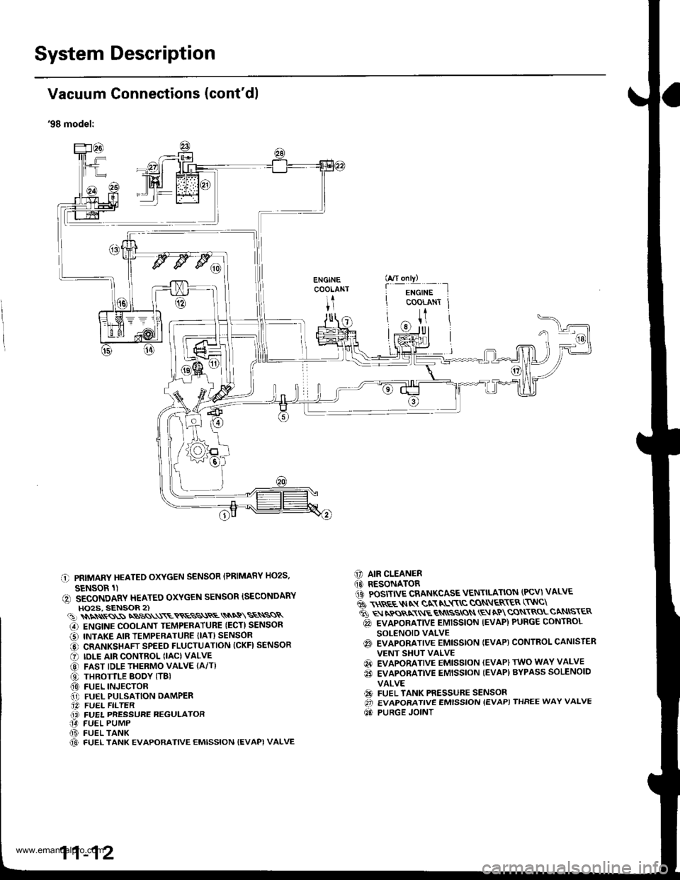
System Description
I
I
I
Vacuum Connections (cont'dl
'98 model:
C PRIMARY HEATEO OXYGEN SENSOR (PRIMARY HO2S,
SENSOR 1)(, SECONDARY HEATEO OXYGEN SENSOR ISECONDARYHO2S, SENSOR 2)(!)\\\\ss\SNBSS\\\ETRESS\RE\\NQ\SE\SSR
G) ENGINE COOLANT TEMPERATUBE (ECT) SENSOR
O INTAKE AIR TEMPERATURE {IAT} SENSOR
@ CRANKSHAFT SPEED FLUCTUATION (CKFI SENSOR
O IDLE AIR CONTROL (IAC) VALVE
@ FAST IDLE THERMO VALVE (A/T)
O THROTTLE BODY (TBI(0) FUEL INJECTOR.1' FUEL PULSATION DAMPER.14 FUEL FILTER(i FUEL PRESSURE REGULATOR14 FUEL PUMP(D FUEL TANK@ FUEL TANK EVAPORATIVE EMISSION {EVAPI VALVE
C] AIR CLEANER(O RESONATOR1iC POSITIVE CRANKCASE VENTILATION (PCV) VALVE
6 \$REE$IN gN NL$\C CON\ER\ER (TNC\
ti q rpos,xr E qN
ssros \E aP cqN\RoLcaNtsr€R
@ EVAPORATIVE EMISSION IEVAP) PURGE CONTROL
SOLENOID VALVEq3 EVAPORATIVE EMISSTON IEVAP} CONTROL CANISTER
VENT SHUT VALVE
@ EVAPORATIVE EMISSION (EVAP) TWO WAY VALVE
€i EVAPORATIVE EMISSION {EVAP) BYPASS SOLENOID
VALVE
€9 FUEL TANK PRESSURE SENSOROi EVAPORATIVE EMISSION {EVAP) THREE WAY VALVE
Qd PURGE JOINT
G/T only)
f
-i*'";-t
COOLANT Jt
U
11-12
www.emanualpro.com
Page 217 of 1395
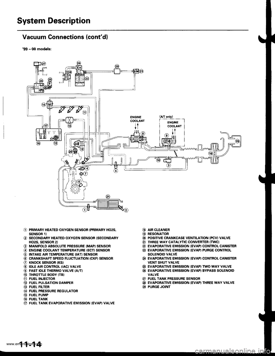
System Description
Vacuum Connections (cont'dl
'99 - q) models:
ENGINECOOLANT
t
o
o
o@
o@@@@@@@@@(t
PRIMARY HEATED OXYGEN SENSOR IPRIMARY HO2S,SENSOR 1lSECONDARY HEATED OXYGEN SENSOR {SECONDARYHO2S. SENSOR 2lMANIFOLD ABSOLUTE PRESSURE (MAPI SENSORENGINE COOLANT TEMPERATURE IECN SENSORINTAKE AIR TEMPERATURE IIATI SENSORCRANKSHAFT SPEED FLUCTUATION {CKF) SENSORKNOCK SENSOR (KS}
IDLE AIR CONTROL IIACI VALVEFAST IDLE THERMO VALVE {A/T}THROTTLE BODY (TB}
FUEL INJECTORFUEL PULSATION DAMPERFUEL FILTERFUEL PRESSURE REGULATORFUEL PUMPFUEL TANKFUEL TANK EVAPORATIVE EMISSION (EVAPI VALVE
AIR CLEANERRESONATORPOSITIVE CRANKCASE VENTILATION (PCV} VALVETHREE WAY CATALYTIC CONVERTER ITWCIEVAPORATIVE EMISSION {EVAPI CONTROL CANISTEREVAPORATIVE EMISSION IEVAPI PURGE CONTROLSOLENOID VALVEEVAPORATIVE EMISSION {EVAPI CONTROL CANISTEFVENT SHUT VALVEEVAPORATIVE EMISSION IEVAPI TWO WAY VALVEEVAPONANVE EMISSION {EVAPI AYPASS SOLENOIDVALVEFUEL TANK PRESSURE SENSOBEVAPORATIVE EMISSION IEVAPI THREE WAY VALVEPURGE JOINT
@@@@@@
@
@@
@@@
11-14
www.emanualpro.com
Page 266 of 1395

Troubleshooting
Troubleshooting Procedures (cont'dl
Symptom Chart
Listed below are symptoms and probable causes for problems that DO NOT cause the Malfunction Indicator Lamp (MlL) tocome on. lf the MIL was reported on, go to page 11-60.Troubleshoot each probable cause in the order listed (from left to right) until the symptom is eliminated,The probable cause and troubleshooting page reference can be found below.
Other Probable Causes for an engine that will not start:- Compression- Intake air leakage- Engine locked up- Timing belt- Starting system- Overheating- Battery
SYMPTOMPROBABLE CAUSE
Engine will not sta rt4, 2,3,5,20, 't5, 1
Hard starting2, 4, 12,17, 14, 't9
Cold fast idle too low7, a,9, 6, 17
Cold fast idle too high7,8,9,11,10
ldle speed fluctuates9,7,8, 't1, 10
Misfire or rough runningTroubleshoot for misfire on pages '11-126, 1|21LOl/\/ power2, 10,11, 13, '17, 18,20
Engine stalls2, 4, 12,1,20,9,5, 't6
Probable Cause List (For the DTC Ch8rt, see page ll-75.)
Probable CausePageSystem
Engine controt ruoaute (ecvtffi'I11-42
I 1-178Fuel oressure
PGM-Fl main relav
lgnition system
Crankshatt Position/Top Dead Center/Cylinder position sensor circuit
Intake Air Temperature (lAT) sensor ctrculr
ldle Air Control (lAC) Vatve
Fast idle thermo valve
ldle speed adjustment
Throttle body
Throftle cable
Manifold Absolute P."""rr"ffi
Throftle Position (TP) sensor
Barometric pressur" (gnno-
Ay'T gear position signal
Brake switch signal
Air Cleaner
Three Way Catalytic Converter (TWC)
Evaporative emission (EVAP) control
Contaminated fuel
1 1- 187
Section 4
5't1-'t31,146
6I '�t-95
711-152
81'l-168
1 1- 169
1011-196'1111-'194
12'1 'l -90
1 1- 103
1411-137
15Section 14
161 1- 166
17r 1-194
181 1,199'1911-203
20
11-64
www.emanualpro.com