wire HONDA CR-V 2000 RD1-RD3 / 1.G Workshop Manual
[x] Cancel search | Manufacturer: HONDA, Model Year: 2000, Model line: CR-V, Model: HONDA CR-V 2000 RD1-RD3 / 1.GPages: 1395, PDF Size: 35.62 MB
Page 1117 of 1395
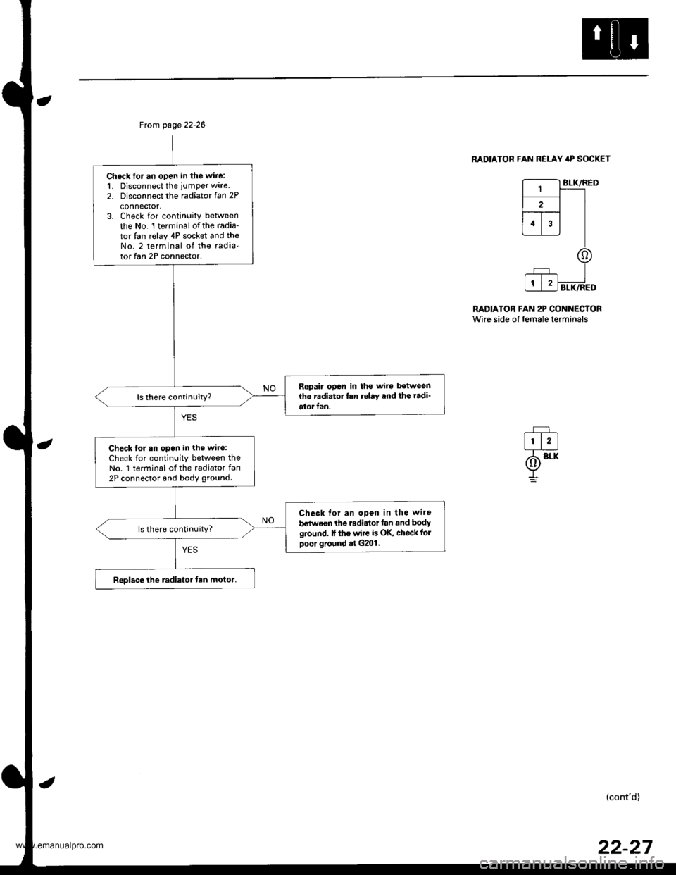
Ch6ck for an open in the wire:1. Disconnect the jumper wire.
2. Disconnect the radiator fan 2P
3. Check for continuity beNveenthe No. l terminal o{the radia-tor fan relay 4P socket and theNo. 2 terminal of the radia'tor fan 2P connector-
Repai. open in the wira betweenthe radiator fan .olay ,nd the radi'atorfan.
Check lor an open in the wi.e:Check for continuity between theNo. 1 terminal oI the radiator fan2P connector and body ground.
Check lor an open in the wir.
b€turosn the radi.tor fan and bodyground. lf ihe wire b OK, check folpoor ground .t G2()l .
ls there continuity?
Replace the radiator tan motor.
Ftom page 22-26
RADIATOR FAN REI-AY 4P SOCKET
BLK/RED
RADIATOR FAN 2P CONNECTORWire side of lemale terminals
(cont'd)
www.emanualpro.com
Page 1118 of 1395
Troubleshooting
Radiator Fan (cont'dl
From page 22-26
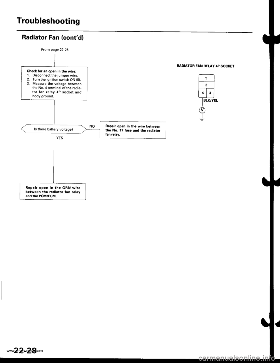
RADIATOR FAN RELAY 4P SOCKET
BLK/YEL
1
2
a
Chock for an open in the wire:'1. Disconnect the jurnper wire.2. Turn the ignition switch ON (ll).3. lleasure the voltage betweenthe No.4terrninal of the radia-tor fan relay 4P socket andbody ground.
R€pair open in th6 wire botwoonthe No. 17 fuso and the radiatolfan .elsy.
ls there battery voltage?
Rep.ir open in the GRN wirebotw€en lhe radiator tan relayand the PCM/ECM.
22-28
www.emanualpro.com
Page 1119 of 1395
Condenser Fan
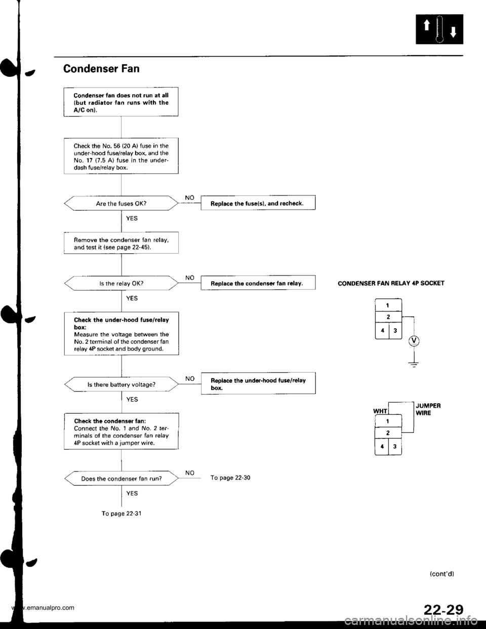
CONDENSER FAN RELAY 4P SOCKET
(cont'd)
Condenser lan does not run at alllbut radiator fan runs with theA/C on).
Check the No. 56 (20 A) fuse in theunder hood fuse/relay box, and theNo. 17 {7.5 A) fuse in the under-dash fuse/relay box.
Replace the luse(s), and .echeck.
Remove the condenser fan relay,and test it (see page 22-45).
Replace the condenser fan r€lay.
Check the under-hood luso/relaybox:Measure the voltage between theNo.2 terminal of the condenserfanrelay 4P socket and body ground.
Check the condensff fan:Connect the No. 1 and No. 2 terminals of the condenser lan rclay4P socket with a jumperwire.
Does the condenser fan run?page 22-30
To page 22 31
22-29
www.emanualpro.com
Page 1120 of 1395
![HONDA CR-V 2000 RD1-RD3 / 1.G Workshop Manual
Troubleshooting
Condenser Fan {contd)
CONDENSER FAN RELAY 4P SOCKET
r---------t wHT
lr_f__l12 | |
fT;.] |I/Or\j/
I
G
CONDENSER FAN 2P CONNECTORWire side ol temale torminals
-r+-,.12
TBtK
@
!
Chock f HONDA CR-V 2000 RD1-RD3 / 1.G Workshop Manual
Troubleshooting
Condenser Fan {contd)
CONDENSER FAN RELAY 4P SOCKET
r---------t wHT
lr_f__l12 | |
fT;.] |I/Or\j/
I
G
CONDENSER FAN 2P CONNECTORWire side ol temale torminals
-r+-,.12
TBtK
@
!
Chock f](/img/13/5778/w960_5778-1119.png)
Troubleshooting
Condenser Fan {cont'd)
CONDENSER FAN RELAY 4P SOCKET
r---------t wHT
lr_f__l12 | |
fT;.] |I/Or\j/
I
G
CONDENSER FAN 2P CONNECTORWire side ol temale torminals
-r+-,.12
TBtK
@
!
Chock for an open in the wire:'1. Disconnect the iumper wire.2. Disconnect the condenser fan2P connector.3. Check for continuity betweenthe No. 1 terminal of the con,denser fan relay 4P socket andthe No. 2 terminal of the con-denser fan 2P connector.
Ropair open in the wire betwoenth€ condenser fan rslay and thecondenser tan.
ls there continuity?
Chech tor an open in the wire:Check for continuity between theNo. I terminal of the condenserfan 2P connector and bodyground.
Check for an open in thg wirebetween the condenser fan andbody ground. lf the wiro is OK.check tor poor ground .t G202.
Replace tho condenser tan motor.
22-30
www.emanualpro.com
Page 1121 of 1395
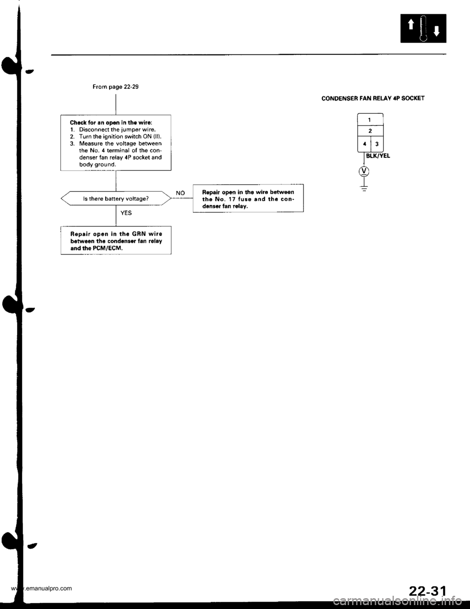
Chock for an open in the wiro:1. Disconnect the iumper wire.2. Turn the ignition switch ON (ll).
3. Measure the voltage betweenthe No. 4 terminal oI the con-denser fan relay 4P socket andbody ground.
Repair opcn in tho wire betwoonthe No. 17 tuse and the con-densea fan relay,
Repair open in the GRN wirob6tw6en the cond.nser lan relayand rhe PcM/EcM,
Ftorn page 22-29
CONDENSER FAN RELAY 4P SOCKET
22-31
www.emanualpro.com
Page 1122 of 1395
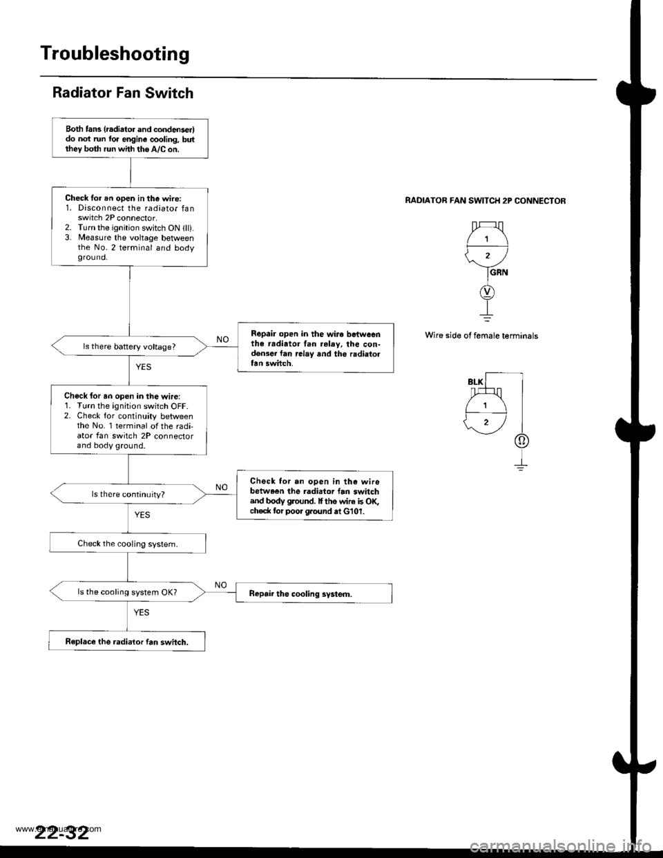
Radiator Fan Switch
RADIATOB FAN SWITCH 2P CONNECTOR
1
'.r
GRN
Wire side of female terminals
Both tans (radiator and condenser)do not run fo. engine cooling, butthey both run with the A/C on.
Check lor rn open in the wire:1. Disconnect the radiator fanswitch 2P connector.2. Turn the ignition switch ON lll).3, Measure the voltage betlveenthe No.2 terminal and bodygrou nd.
Repair open in the wire betweenthe radiator tan relay, the con-densei lan .elay and the radiaiortan swhch.
ls there battery voltage?
Chock for an open in the wire:1. Turn the ignition switch OFF.2. Check for continuity betweenthe No. 1 terminal of the radi-ator fan switch 2P connectorand body ground.
Check for an open in the wirebetween the .adialor fan switchand body glound. I ths wire is OF;choc* tor poor g.ound at G'101.
ls there continuity?
ls the cooling system OK?
Replsce the radialor fan switch.
www.emanualpro.com
Page 1123 of 1395
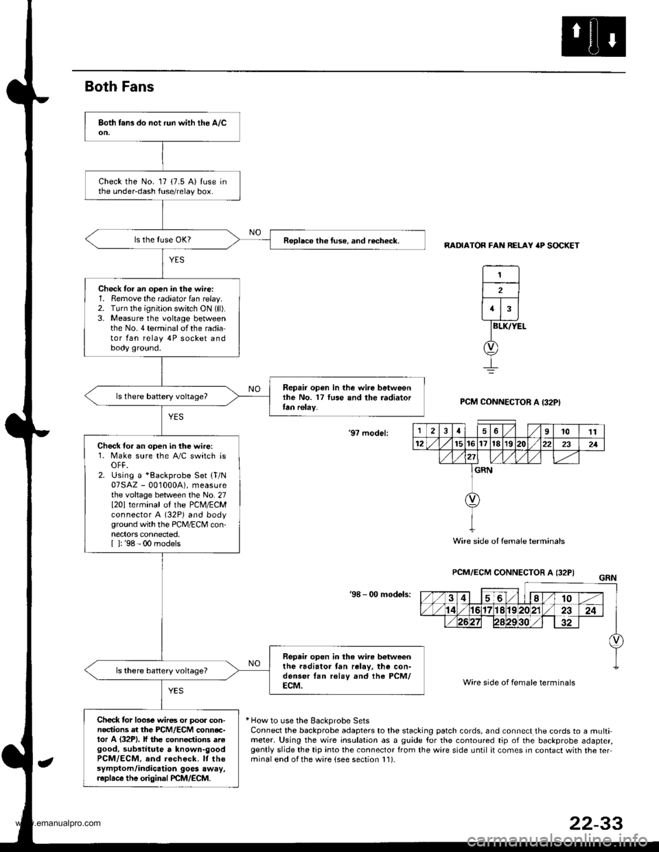
Both Fans
RADIATOR FAN RELAY 'P SOCKET
BLK/YEL
PCM CONNECTOR A I32PI
'9? model:
PCM/ECM CONNECTOR A (32PI
'98 - 0O mod6ls:
Wire side of female terminals
* How to use the Backprobe SetsConnect the backprobe adapters to the stacking patch cords, and connect the cords to a multimeter. Using the wire insulation as a guide for the contoured tip of the backprobe adapter,gently slide the tip into the connector from the wire side until it comes in contact with the terminal end ofthe ware {see section l1).
Check the No. 17 (7.5 A) tuse inthe under-dash fuse/relay box.
Reolace the tuse. and recheck.
Check for an op€n in the wire:1. Remove the radiator fan relay.2. TLrrn the ignition switch ON (ll).
3. Measure the voltage betweenthe No.4 terminalofthe radiator fan relay 4P socket andbody ground.
Repair open in the wire betweenlhe No. 17 luse and the radiatortan relay.
Check for an open in the wire:1. Make sure the A/C switch isOFF.2. Using a *Backprobe Set {T/N07SAZ - 001000A), measurethe voltage between the No. 27I20l terminal ol the PCM/ECMconnector A (32P) and bodyground with the PCM/ECM con-nectors connected.[ ]: '98 - 00 models
Repair open in the wire b€tweenthe.adiator fan ralav, the con-denser tan rolay and the PCM/ECM.
Check tor loose wires or poor con-nodions at the PCM/ECM connoc-tor A (32P1. lf the connections arcgood, substitute a known-goodPCM/ECM, and recheck. It thesymptom/indicalion goes away,r.plrce the original PCM/ECM.
1
2
1
12461011
12t5t61718r9222321
GRN
Wire side oI female terminals
22-33
www.emanualpro.com
Page 1124 of 1395
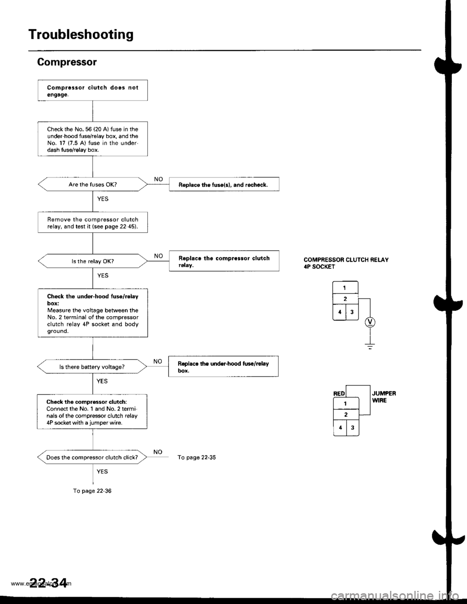
Troubleshooting
To page 22-35
Check the No. 56 (20 A) fuse in theunder hood fuse/relay box, and theNo. 17 (7.5 A) fuse in the underdash luso/rglay box.
Replace the fuso(sl, and r6check.
Remove the compressor clutchrelay, and test it (see page 22 45).
Check the under-hood fuse/relayDOX:Measure the voltage between theNo. 2 terminal of the compressorclutch relay 4P socket and bodyground,
Chack lhe complessor clutch:Connect the No. 1 and No. 2 termi-nals ofthe comoressor clutch relav4P socket with a jumper wire.
Does the comprossor clutch click?
22-34
To page 22-36
www.emanualpro.com
Page 1125 of 1395
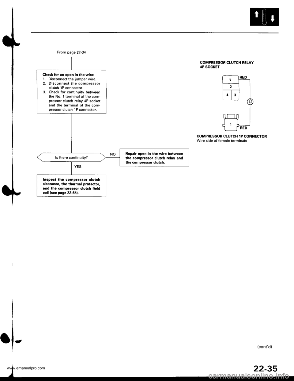
COMPRESSOR CLUTCH RELAYilP SOCKET
COMPRESSOR CLUYCH lP CONNECTORWire side of lemale terminals
-_-l RED
tr-=--l II
I.TT
@
I
$"f Ii 1 __---.1
1___J.RED
I
I
+
Ftom page 22-34
Check for an open in the wire:1. Disconnect the jumper wire.2. Disconnect the compressorclutch 1P connoctor.3. Check for continuity betweenthe No. 1 terminal of the com-pressor clutch relay 4P socketand the terminal ol the com-pressor clutch 1P connector.
Repair open in the wire betweenthe comp.e3sor clutch relay andthe comprsssor clutch.
Inspect tha compreslor clutchclearanco, the thormal protector,
and ths comDrg$or clutch tioldcoil lsee page 22-65).
I
I
.l-(cont'd)
www.emanualpro.com
Page 1126 of 1395
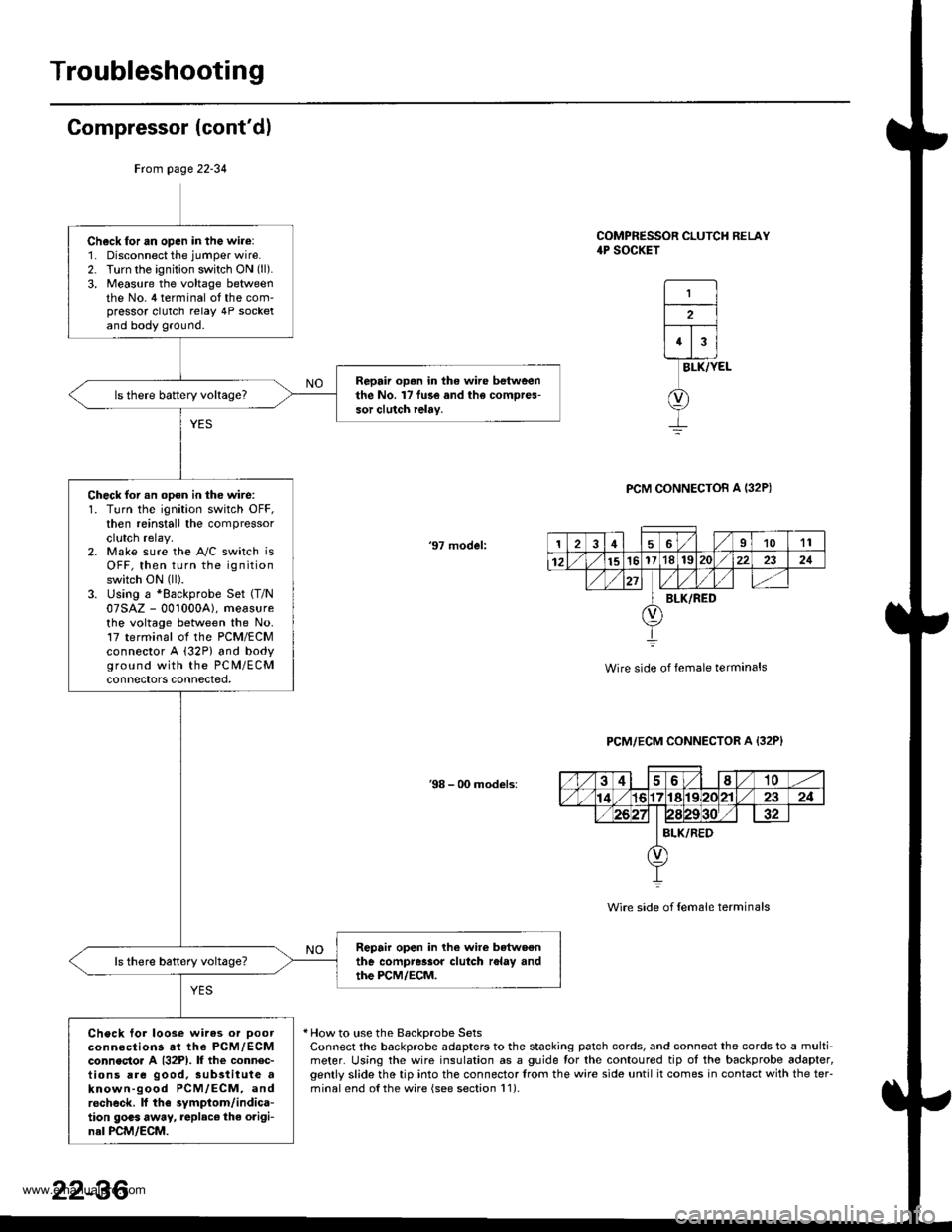
Troubleshooting
Compressor (cont'dl
COMPRESSOR CLUTCH RELAY4P SOCKET
1
2
43
BLK/YEL
PCM CONNECTOB A I32P)
'97 model:
Wire side of female terminals
PCM/ECM CONNECTOR A {32P}
38 - 00 models:
Wire side of {em6le terminals
* How to use the BackDrobe SetsConnect the backprobe adapters to the stacking patch cords, and connect the cords to a multi-meter. Using the wire insulation as a guide for the contoured tip ot the backprobe adapter,gently slide the tip into the connector trom the wire side until it comes in contact with the teFminalend o{the wire {see section l1).
Frcm page 22-34
Ch6ck for an open in the wire:1. Disconnect the jumper wire.2. Turn the ignition switch ON (ll).
3, Measure the voltage betweenthe No. 4 terminal ot the com'pressor clutch relay 4P socketand body ground.
Repair op.n in the wire betweenthe No. l7 fu3e and the compres-sor clutch ielay.
Check for an opon in the wire:1. Turn the ignition switch OFF,then reinstall the compressorclutch relay.2. Make sure the A"/C switch isOFF, then turn the ignitionswitch ON (ll).
3. Using a *Backprobe Set (T/N
07SAZ - 001000A), measurethe voltage between the No.17 terminal ol the PCM/ECMconnector A (32P) and bodyground with the PC M/ECMconnectors connected,
Repair open in lhe wire betwoonthe compressor clutch r6lay andthe PCM/ECM.
Check tor loose wires or Doorconnections at the PCM,/ECMconnecto. A {32P1. lf the connec-tions are good, sub3titute aknown-good PCM/ECM, androcheck. lf the symptom/indica-tion goas away, replac€ the origi-nal PCM/ECM.
126I1011
12151617'181S222321
BLK/RED
22-36
www.emanualpro.com