wire HONDA CR-V 2000 RD1-RD3 / 1.G Workshop Manual
[x] Cancel search | Manufacturer: HONDA, Model Year: 2000, Model line: CR-V, Model: HONDA CR-V 2000 RD1-RD3 / 1.GPages: 1395, PDF Size: 35.62 MB
Page 1051 of 1395
Seats
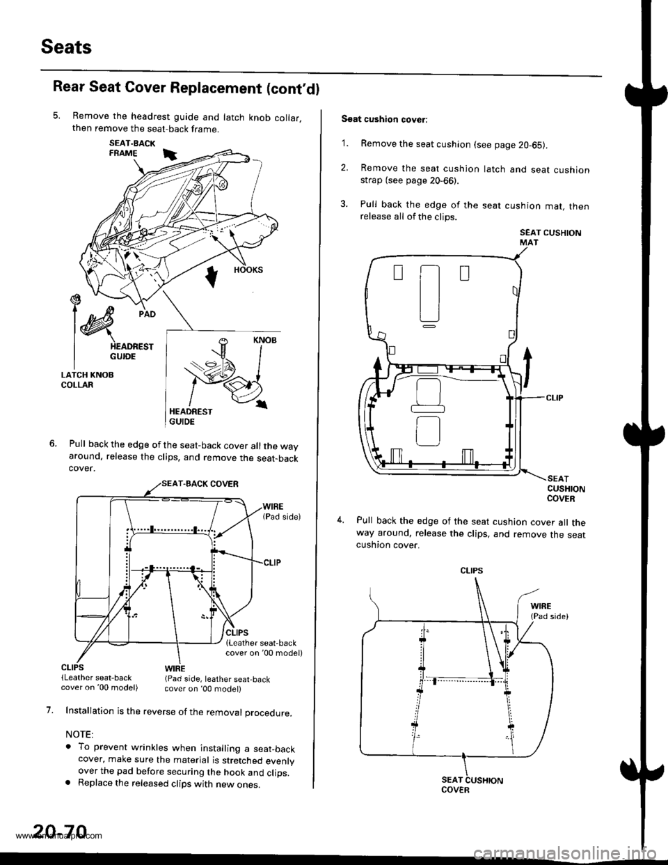
Rear Seat Cover Replacement (cont'dl
Remove the headrest guide and latch knob collar,then remove the seat-back frame.
SEAT.BACKFRAME i
Pull back the edge of the seat-back cover all the wayaround. release the clips, and remove the seat-backcover.
€ --t)c/
l@
pio
I HEADREST
I GUroE
LATCH KNOBCOLLAR
CLIPS(Leather seat-backWIRE(Pad side, leather seat,back
1.
20-70
cover on '00 model) cover on ,00 model)
Installation is the reverse of the removal procedure.
NOTE:
o To prevent wrinkles when installing a seat_backcover, make sure the material is stretched evenlyover the pad before securing the hook and clips.. Replace the released clips with new ones.
Soat cushion cover:
'1. Remove the seat cushion (see page 20-65).
2. Remove the seat cushion
strap (see page 20-66).
3. Pull back the edge of the
release all of the clips.
latch and seat cushion
seat cushion mat, then
SEAT CUSHIONMAT
CUSHIONCOVER
Pull back the edge of the seat cushion cover all theway around, release the clips, and remove the seatcushton cover.
t-t
tl
L]
CLIPS
COVER
www.emanualpro.com
Page 1052 of 1395
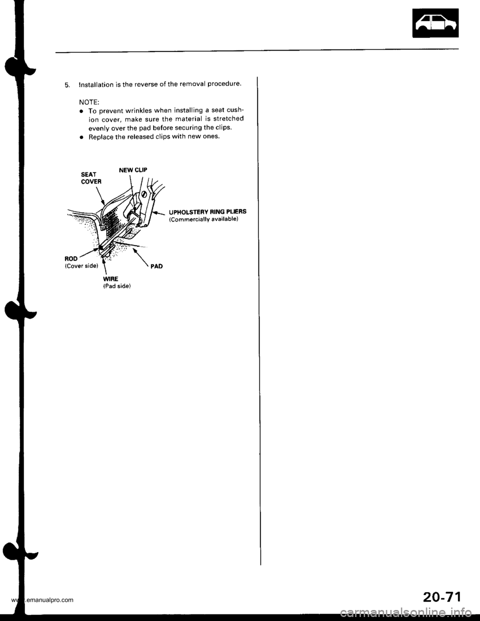
5. Installation is the reverse of the removal procedure.
NOTE:
o To prevent wrinkles when installing a seat cush-
ion cover, make sure the material is stretched
evenly over the pad before securing the clips.
. Replace the released clips with new ones.
UPHOLSTERY FING PUERS(ComE|erciallY available)
WIRE(Pad side)
PAD
20-71
www.emanualpro.com
Page 1082 of 1395
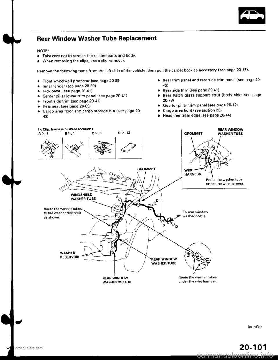
Rear Window Washer Tube Replacement
NOTE:
. Take care not to scratch the related parts and body.
. When removing the clips, use a clip remover.
Remove the following parts from the left side of the vehicle, then
. Front wheelwell protector (see page 20-89)
. Innertender (see page 20-89)
. Kick panel (see page 20-4't)
. Center pillar lower trim panel (see page 20-41)
. Front side trim (see page 20-41)
. Rear seat (see page 20-63)
a Cargo area floor and cargo storage bin (see page 20-
43)
>: Clip, harness cu3hion location3c>,3D>,12A>, 1B>, 1
Route the washer t!be
under the wire harness
Route the washer tubesto the washer reservoir
WASHEBRESERVOIR
wasner no2zre.
@s_l el 4
WINDSHIELDWASHEB TUBE
REAR WINDOWWASHER MOTOR
GROMMET
wrNoowWASHER TUBE
pull the carpet back as necessary (see page 20-45)
. Rear trim panel and rear side trim panel (see page 20-
42J
. Rear side trim (see page 20-41)
. Rear hatch glass support strut (body side, see page
20-7Al
. Ouarter pillartrim panel (see page 20-421
o Cargo area light (see section 23)
. Headliner (rear edge, see page 20-44)
GROMMET
(cont'd)
20-101
www.emanualpro.com
Page 1083 of 1395
Wiper/Washer
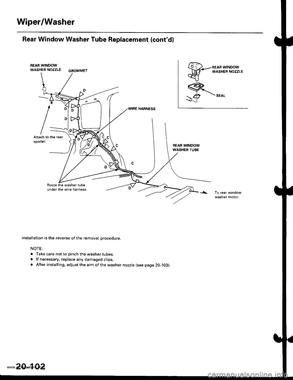
Rear Window Washer Tube Replacement (cont'dl
REAR WINDOWWASHER NOZZLE GSOMMET
\
t
i;r."'..--a
B
REAR WINDOWWASHER TUBE
Route the washer tubeundor the wire harness,
Installation is the reverse of the removal Drocedure.
NOTE;
. Take care not to pinch the washer tubes.. lf necessary, replace any damaged clips.. After installing, adjust the aim of the washer nozzle (see page 20-103).
20-102
www.emanualpro.com
Page 1095 of 1395
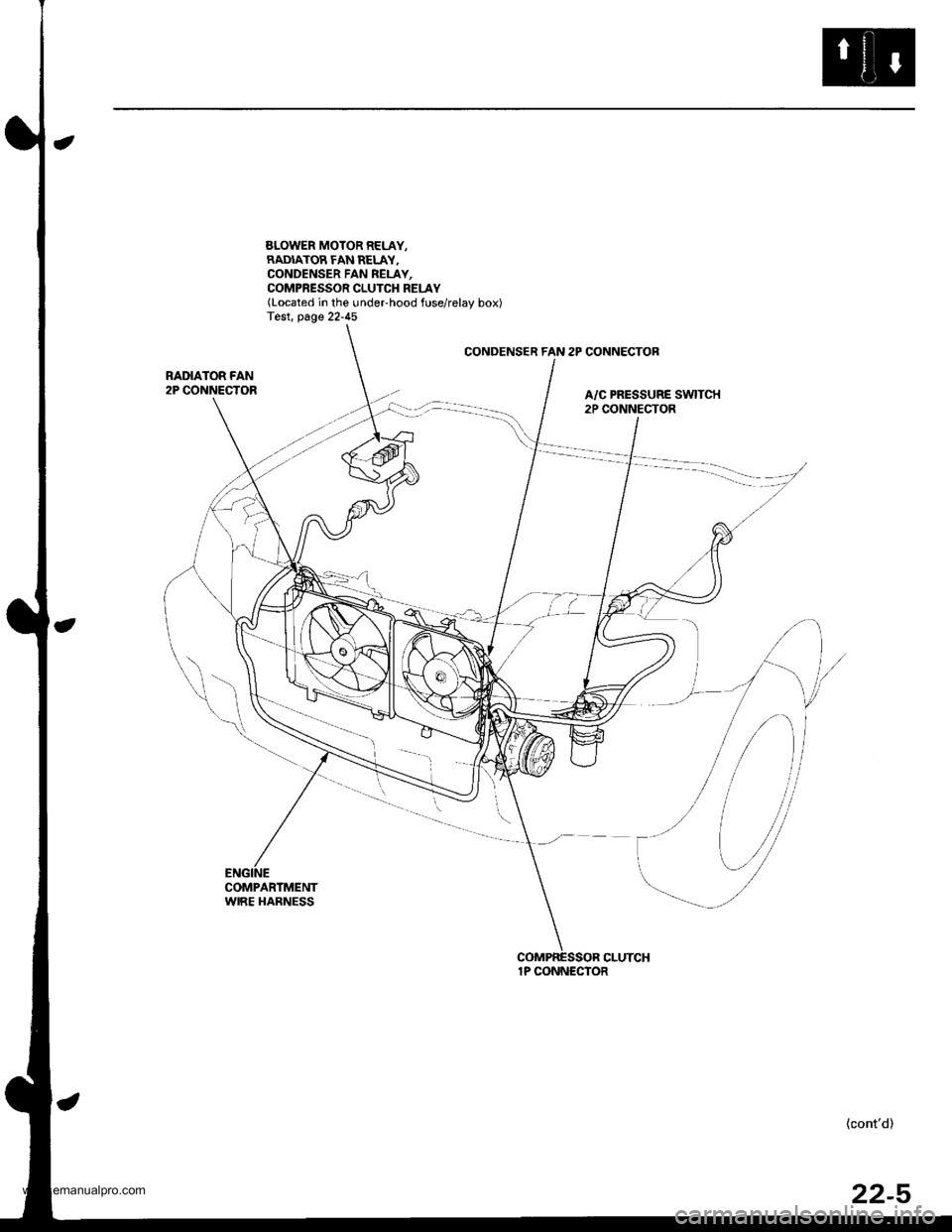
SLOWER MOTOR RELAY,RADIATOR FAN RELAY.CONDENSER FAN REI-AY,COMPRESSOR CLUTCH RELAY(Located in the undeFhood fuse/relay box)Test. page 22-45
CONDENSER FAN 2P CONNECTOB
RADIATOR FAN2P CONNECTORA/C PRESSURE SWITCH2P CONNECTOR
COMPARTMENTWIRE HARNESS
{cont'd)
1P CONNECTOR
22-5
www.emanualpro.com
Page 1096 of 1395
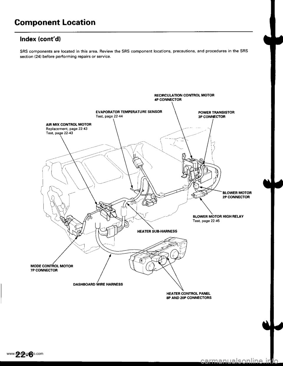
Component Location
Index (cont'dl
SRS components are located in this area. Review the SRS component locations, precautions, and procedures in the SRS
section (24) before performing repairs or service.
BECIRCULATION CONTROL MOTOR4P CONNECTOR
EVAPORATOR TEMPERATURE SENSORTesl, page 22-44POWER TRANSISTOR3P CONNECTOR
AIR MIX CONTROL MOTORReplacement, page 22-43lest, page 22-13
BLOWER MOTOB2P CONNECTOR
BLOWER MOTOR HIGH RELAYTest, page 22-45
HEATER SUB.HARNESS
7P CONNECTOR
DASHBOARD WIRE HARNESS
HEATER CONTROL PANEL8P AND 2OP CONNECYORS
22-6
www.emanualpro.com
Page 1102 of 1395
Troubleshooting
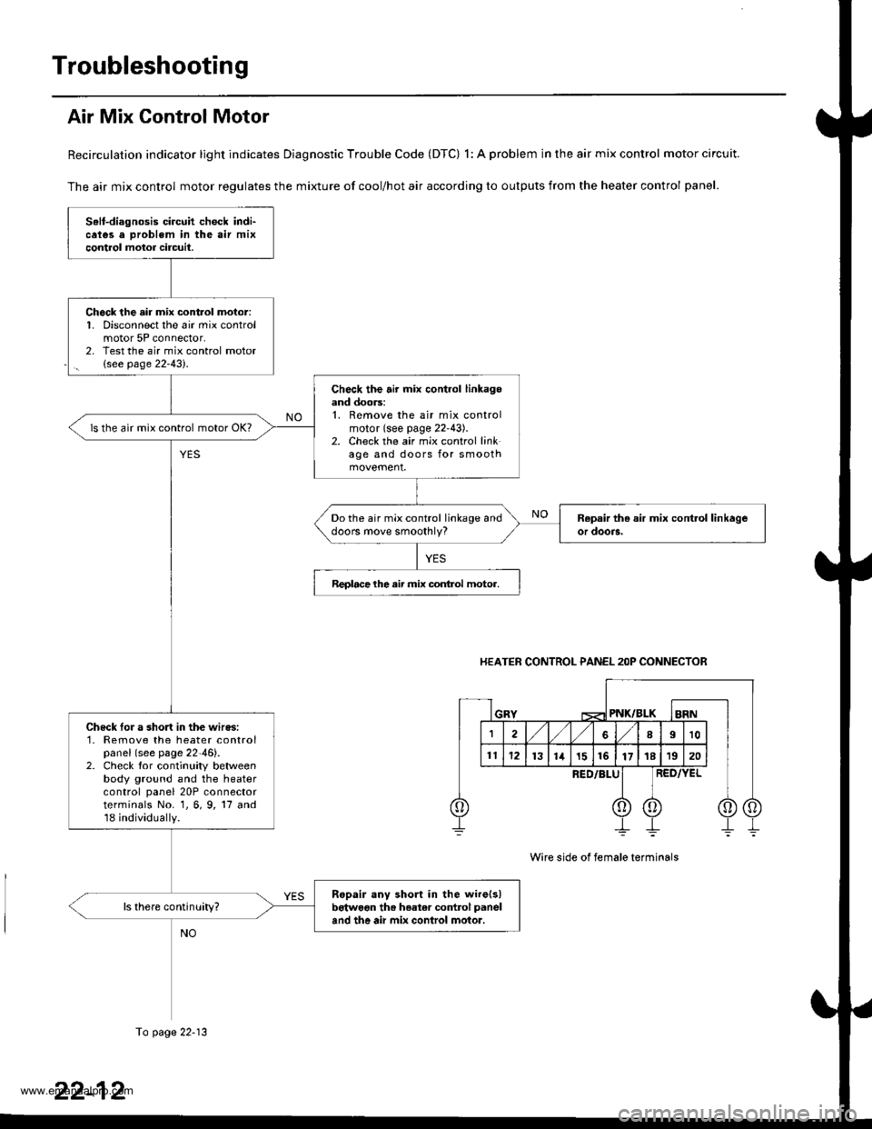
Air Mix Control Motor
Recirculation indicator light indicates Diagnostic Trouble Code (DTC) 1: A problem in the air mix control motor circuit.
The air mix control motor regulates the mixture of cool/hot air according to outputs from the heater control panel.
Selt-diagnosis circuit check indi-cates a Droblem in the air mixcontrol motor circuil.
Chock the air mix control moior:1. Disconnect the air mix controlmotor 5P connector,2, Test the air mix control motor(see page 22-43).
Check the air mix control linkagoand doors:1. Remove the air mix controlmotor (see page 22'43).2. Check the air mix control linkage and doors for smooth
ls the air mix control motor OK?
Do the air mix control linkage anddoors move smoothly?
Reolacelhe air mix conlrol motor.
Check Ior a short in the wires:1- Remove the heater controlpanel (see page 22-46).2. Check tor continuity betweenbody ground and the heatercontrol panel 20P connectorterminals No. 1, 6, 9, 17 and18 individually.
Ropair any short in the wire(s)betwoon th. heater co.rtrol panel
and the air mix conlrol motor.
HEATER CONTROL PANEL 2OP CONNECTOR
PNK/BLK
RED/BLU
Wire side of female terminals
To page 22-13
www.emanualpro.com
Page 1103 of 1395
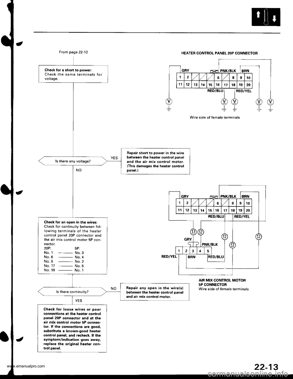
Ftom page 22.12HEATER CONTROL PANEL 2OP CONNECTOR
Wire side ol female terminals
Check tor a short to poweriCheck the same terminals forvoltage.
Repair shon lo power in the wi.ebetween the heater control paneland the air mix control motor,(This damages the heater controlDanel.l
Check tor an open in the wires:Check for continuity between fol-lowing terminals of the heatercontrol panel 20P connector andthe air mix control motor 5P con-nector,zOPi 5P:No. 1 - No.3No.6 _ No. 4No.g _ No.2No. 17 _ No.5No. 18 _ No. 1
Repair any open in the wire{s)betweon the heater control panel
and air mix control motor.
Check toa loos€ wir63 or poorconnections rl the heater controlpanel 20P connector and st theair mix control motor 5P connsc-tor. lJ the connections aro good,substitute a known-good hoatercontrol panel, and rechock. I thesymptom/indication goes away,..pl.ce the original heater con-trol panel.
REO/8LURED/YEL
RED/YEL
AIR MIX CONTROL MOTOR5P CONNECTORWire side of female terminals
www.emanualpro.com
Page 1104 of 1395
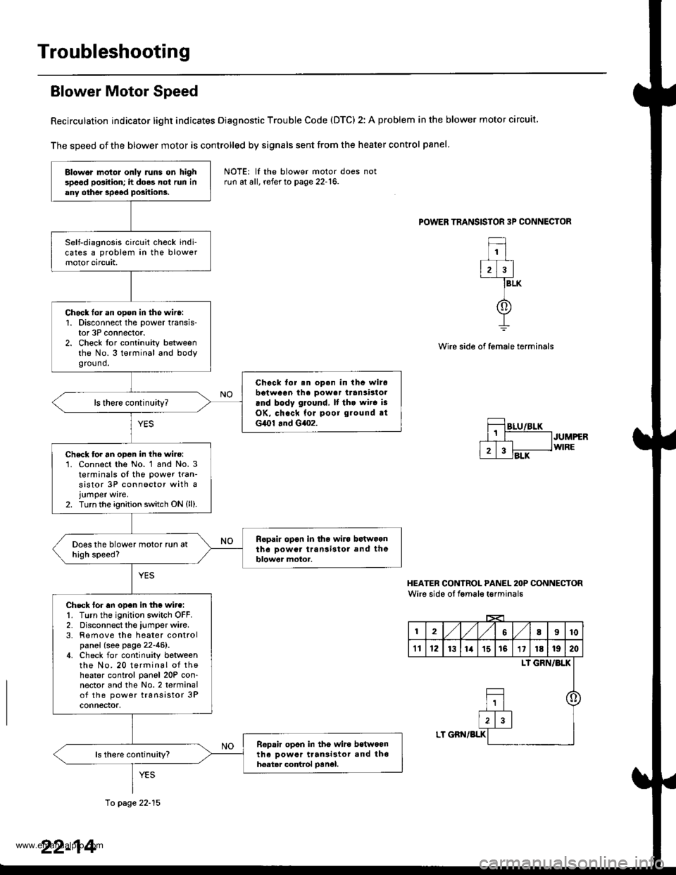
Troubleshooting
Blower Motor Speed
Recirculation indicator light indicates Diagnostic Trouble Code (DTC) 2: A problem in the blower motor circuit
The speed of the blower motor is controlled by signals sent from the heater control panel
POWER TRANSISTOR 3P CONNECTOR
1
2)3
f
BLK
Wire side of female terminals
JUMPERWIRE
HEATER CONIROL PANEL 2OP CONNECTORWire side oI fgmale t€rminals
12,/1,/68I10
't112131ia't51611181920
LI GRN/BLK
o
LT GBN/BLK
Blower motol only runs on highspood position; h does not run inany othe. speod positions.
Self-diagnosis circuit check indi-cates a problem in the blowermotor circuit,
Chack lor.n open in the wire:1. Disconnect the power transis-tor 3P connector.2. Check for continuity betweenthe No.3 terminal and bodygro(1nd.
Chock for.n op.n in thc wirobotween ihe powa. transistorrnd body ground, It tho wir. is
OK, check for poor ground atG,O1 .nd G4o2.
ls there continuity?
Chsck for an opon in the wire:'1. Connect the No. 1 and No. 3t€rminals of the power tran-sistor 3P connector with ajumper ware.2. Turn the ignition switch ON {ll).
Repair op6n in the wiro betwoontho Dower transi3tol and theblowor motor.
Check tor an open in tho wire:1. Turn the ignition switch OFF.2. Disconnect the iumper wire.3. Remove the heater controlpanel (see page 22-46).4. Check for continuity botweenthe No. 20 terminal of theheater control panel 20P con-nector and the No.2 terminalof the power transistor 3Pconnectof,
R€pair opon in tho wire betwoenth6 oowor ttan3i3tor and th6hoatar control oanel.
NOTE: lf the blower motor doesrun at all, refer to page 22-16.
10 page 22-15
22-14
www.emanualpro.com
Page 1105 of 1395
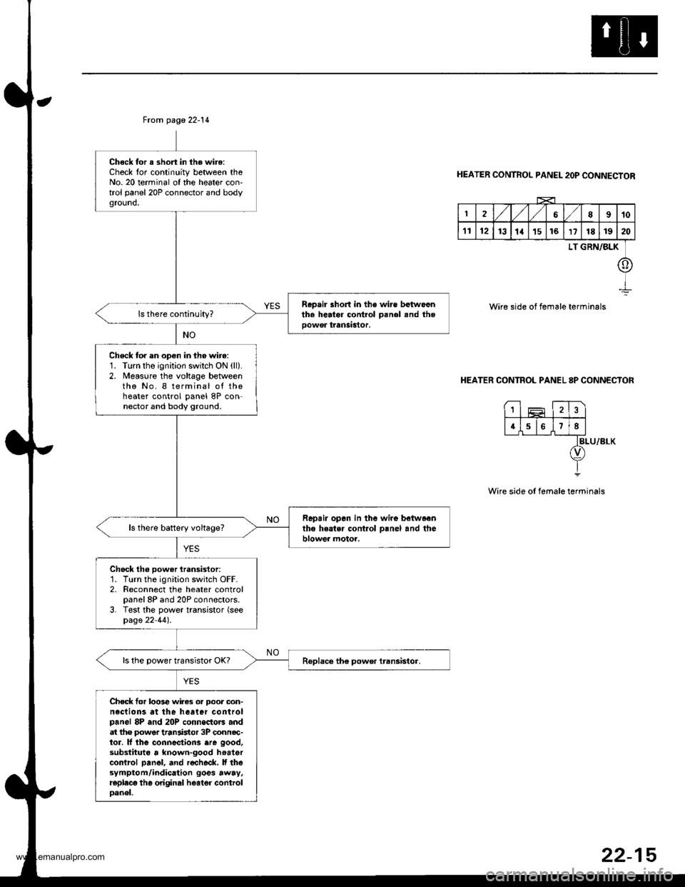
From page 22-14
Chock for a short in the wire:Check tor continuity between theNo. 20 terminal of the heater con'trol panel 20P connector and bodyground,
R.p.ir short in the wire betwoenth. herter control Denel snd theoowor tranSastor.
Check to. an open in the wire:1. Turn the ignition swilch ON (ll).
2. Measure the voltage betweenthe No. I terminal of theheater control panel 8P con-nector and body ground.
Repair opan in the wire betwaentho heatsr cont.ol o.nel and theblower motor.ls there battery voltage?
Chock th6 power iransistor:1. Turn the ignition switch OFF.2. Reconnect the heater controlpanel 8P and 20P connectors.3. Test the power transistor (seepage 22 44).
ls the power transistor OK?
Chec* for loo3e wires or Door oon-neclions at the heater controlpanel 8P and 20P connoctors andat lhe power tran3istor 3P connec-tor. lf lhe connectiorc are good,substituta , known-good hoatercontrcl pan6l, and r€check. ll thesymptom/indication goes away.replecg th6 original heater controloanel.
HEATER CONTROL PANEL 2OP CONNECTOR
2,/1,/l/68910
1112131a151617181920
LT GRN/BLK
o
Wire side of female terminals
HEATER CONTROL PANEL 8P CONNECTOR
BLU/8LK
Wire side of female terminals
1
4678
22-15
www.emanualpro.com