wire HONDA CR-V 2000 RD1-RD3 / 1.G Workshop Manual
[x] Cancel search | Manufacturer: HONDA, Model Year: 2000, Model line: CR-V, Model: HONDA CR-V 2000 RD1-RD3 / 1.GPages: 1395, PDF Size: 35.62 MB
Page 976 of 1395
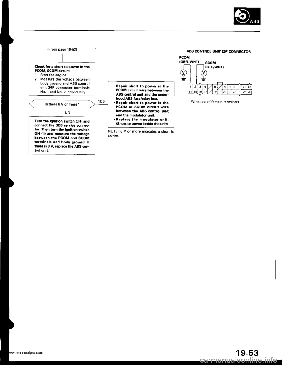
Check fo. a short to power in thaPCOM, SCOM circuhi1. Start the engine.2. Measure the voltage betweenbody ground and ABS controlunit 26P connector terminalsNo. I and No.2 individually.
'Repair short to powor in thsFCOM circuit wiro botwoon th€ABS control unit and the under-hood ABS tuse/r.lay box.. Repeir 3hort to power in thoPCOM or SCOM circuit wirebetwegn tho ABS control uniiand ths modulator unh,. R.placo tha modulatoi unit.(Shon to power in.ido th6 unitl
ls there 8 V or more?
Tu.n tho ignhion switch OFF andconnect thc SCS 3orvice connec-tor. Then turn thc ignition switchON (lll and measure tha voltagobotween the PCOM .nd SCOMtsrminal3 and body gJound. Itther6 is 0 V, .epleco tho ABS con-trol unit.
ABS CONTROL UNIT 26P CONNECTOR
PCOM
Wire side of temale terminals
NOTE: 8 V or more indicates a short to
(GRN/WHTI SCOM
www.emanualpro.com
Page 977 of 1395
Troubleshooting
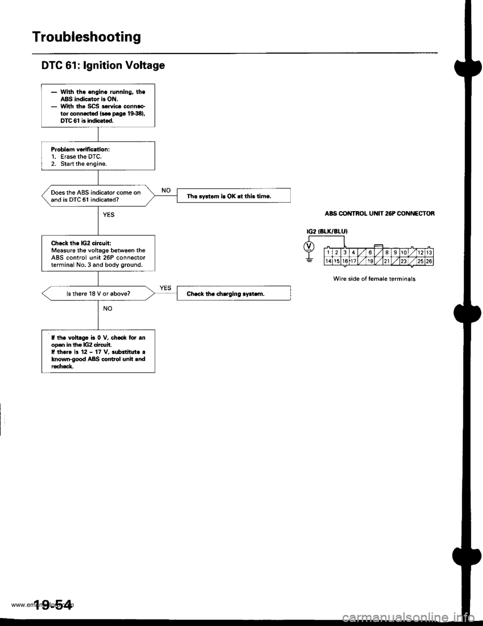
DTC 61: lgnition Voltage
- Whh the .ngine running. theABS indicator b ON,- With the SCS servicc connaetor connoctod {sao prgo 1998},DTC 61 b indi)atod.
Problom vorification:1. Erase the DTC.2. Start the engine.
Does the ABS indicator come onand is DTC 61 indicated?Tho ryrtom i. OK rt thb timo.
Ch.ck the lG2 circuit:Measure the voltage betweon theABS control unit 26P connectorterminal No.3 and body ground.
ls there 18 V or above?
lf the volt gc b 0 V, ch6d( to. anoD€n in lhe lG2 circuh.I thole ir 12 - 17 V, subatilui. !known-good ABS control unit .ndr€d|eck.
Wire side of temale termioals
www.emanualpro.com
Page 981 of 1395
Pulsers/Wheel Sensors
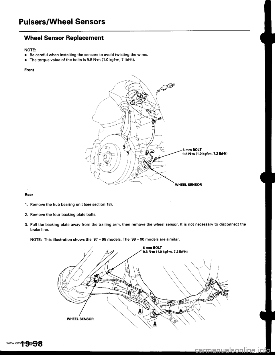
Wheel Sensor Replacement
NOTE;
. Be carefulwhen installing the sensors to avoid twisting the wires.
. The torque value of the bolts is 9.8 N.m ( 1.0 kgf.m, 7 Ibf.ft).
Front
6 mm BOLT9.8 N.m {1.0 kgtm. ?.2lbf'ft)
WHEEL SENSOR
Rgar
1. Remove the hub bearing unit (see section 18).
2. Remove the tour backing plate bolts.
3, Pull the backing plate away from the trailing arm, then remove the wheel sensor. lt is not necessary to disconnect the
brake line.
NOTE: This illustration shows the '97 - 98 models, The '99 - 00 models are similar.
6 mm BOLT9,8 N.m 11.0 kgf.m, 7.2lbf.ft)
\all
19-58
WHEEL SENSOR
www.emanualpro.com
Page 1011 of 1395
Glass
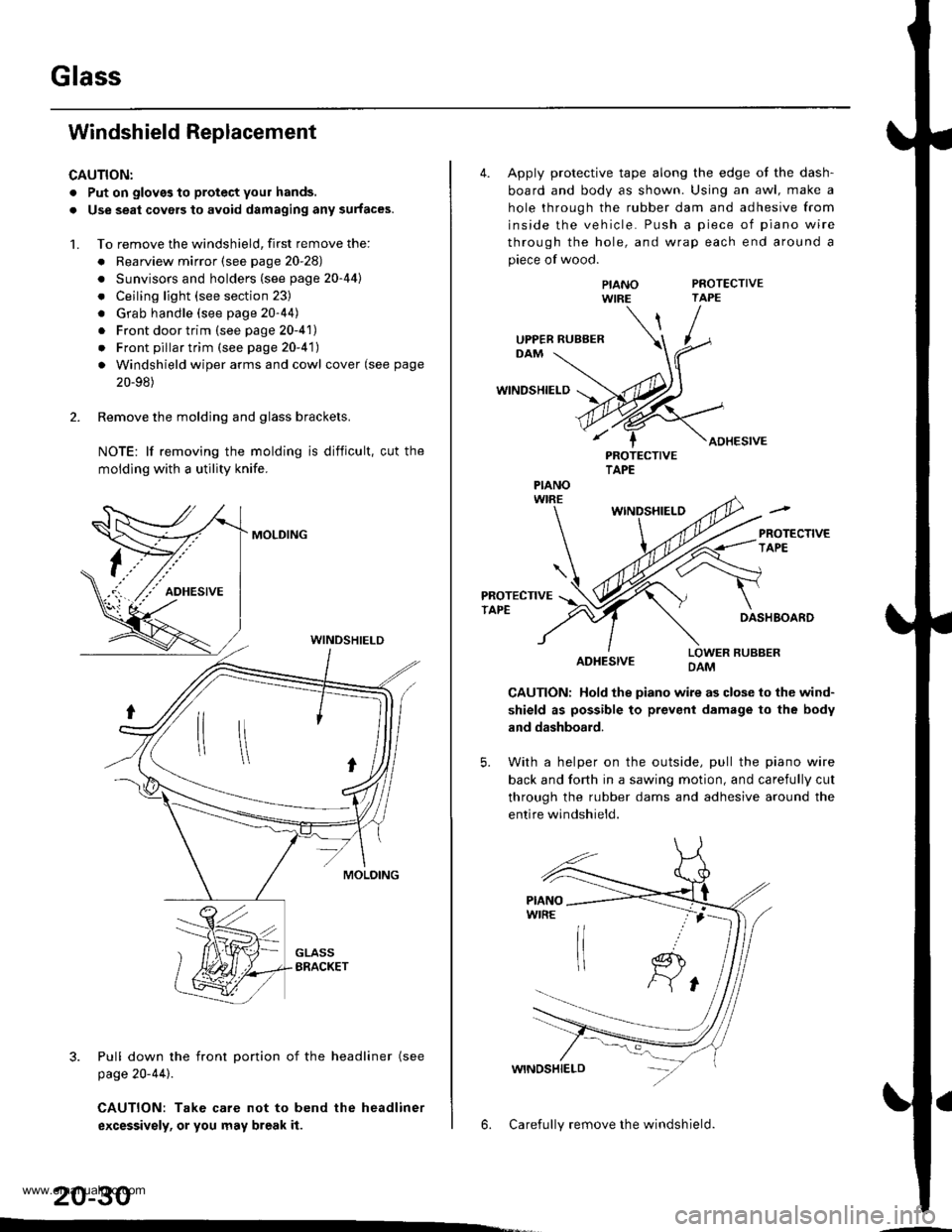
Windshield Replacement
CAUTION:
. Put on gloves to protect your hands.
. Use seat covers to avoid damaging any surfaces.
1. To remove the windshield, first remove the:
. Rearview mirror (see page 20-28)
. Sunvisors and holders (see page 20-44l'
. Ceiling light (see section 23)
. Grab handle (see page 20-44)
. Front door trim (see page 20-41)
. Front pillar trim (see page 20-41)
. Windshield wiper arms and cowl cover (see page
20-98)
2. Remove the molding and glass brackets.
NOTE: lf removing the molding is difficult, cut the
moldlng with a utility knife.
MOLDING
3. Pull down the front Dortion of the headliner (see
page 20-44).
CAUTION: Take care not to bend the headliner
excessivsly, or you may break it.
WINDSHIELD
20-30
4. Apply protective tape along the edge ot the dash-
board and body as shown. Using an awl, make a
hole through the rubber dam and adhesive from
inside the vehicle. Push a piece of piano wire
through the hole, and wrap each end around a
piece of wood.
PROTECTIVETAPE
WINDSHIELD
ADHESIVE
PIANOWIRE
PROTECTIVETAPE
WINDSHIELO
PROTECTIVETAPEDASHBOARD
ADHESIVELOWER RUBBERDAM
CAUTION: Hold the piano wire as close to the wind-
shield as possible to prevent damage to the body
and dashboard.
5. With a helper on the outside, pull the piano wire
back and fo(h in a sawing motion, and carefully cut
through the rubber dams and adhesive around the
entire windshield.
6. Carefully remove the windshield.
UPPER RUBBER
PIANO
www.emanualpro.com
Page 1027 of 1395
![HONDA CR-V 2000 RD1-RD3 / 1.G Workshop Manual
lnterior Trim
5.
Carpet Replacement (contdl
Remove the center lower cover (M/T model).
>: Clip locations,2
lN
-ffi]
6. Remove the SRS unit covers.
>: Clip locations,2
.dL ItEu( |- qf I cARPET
FASTE HONDA CR-V 2000 RD1-RD3 / 1.G Workshop Manual
lnterior Trim
5.
Carpet Replacement (contdl
Remove the center lower cover (M/T model).
>: Clip locations,2
lN
-ffi]
6. Remove the SRS unit covers.
>: Clip locations,2
.dL ItEu( |- qf I cARPET
FASTE](/img/13/5778/w960_5778-1026.png)
lnterior Trim
5.
Carpet Replacement (cont'dl
Remove the center lower cover (M/T model).
>: Clip locations,2
lN'
-ffi]
6. Remove the SRS unit covers.
>: Clip locations,2
.dL ItEu( |- qf I cARPET
FASTENER('98 - 00 models)SNS UNIT
7. '97 model: Cut areas @ and @ in the carpet, then
pullthe carpet back.'98 - 00 models: Release the fastener and cut area
@ in the carpet, then pull the carpet back.
COVER
COVER
20-46
8. Remove the clips, and release the fasteners. then
remove the carpet.
NOTE: Take care not to damage, wrinkle or twist the
carpet.
>: Clip locations.3
FASTENER
lnstallation is the reverse of the removal procedure.
NOTE:
. Take care not to damage. wrinkle or twist the
carper.
. Make sure the seat harness is routed correctly.
. lf necessary, replace any damaged clips.
. Reaftach the cut areas @ and @ ('97 model) or
cut area @ ('98 - OO models) in the carpet with
wire ties.
www.emanualpro.com
Page 1034 of 1395
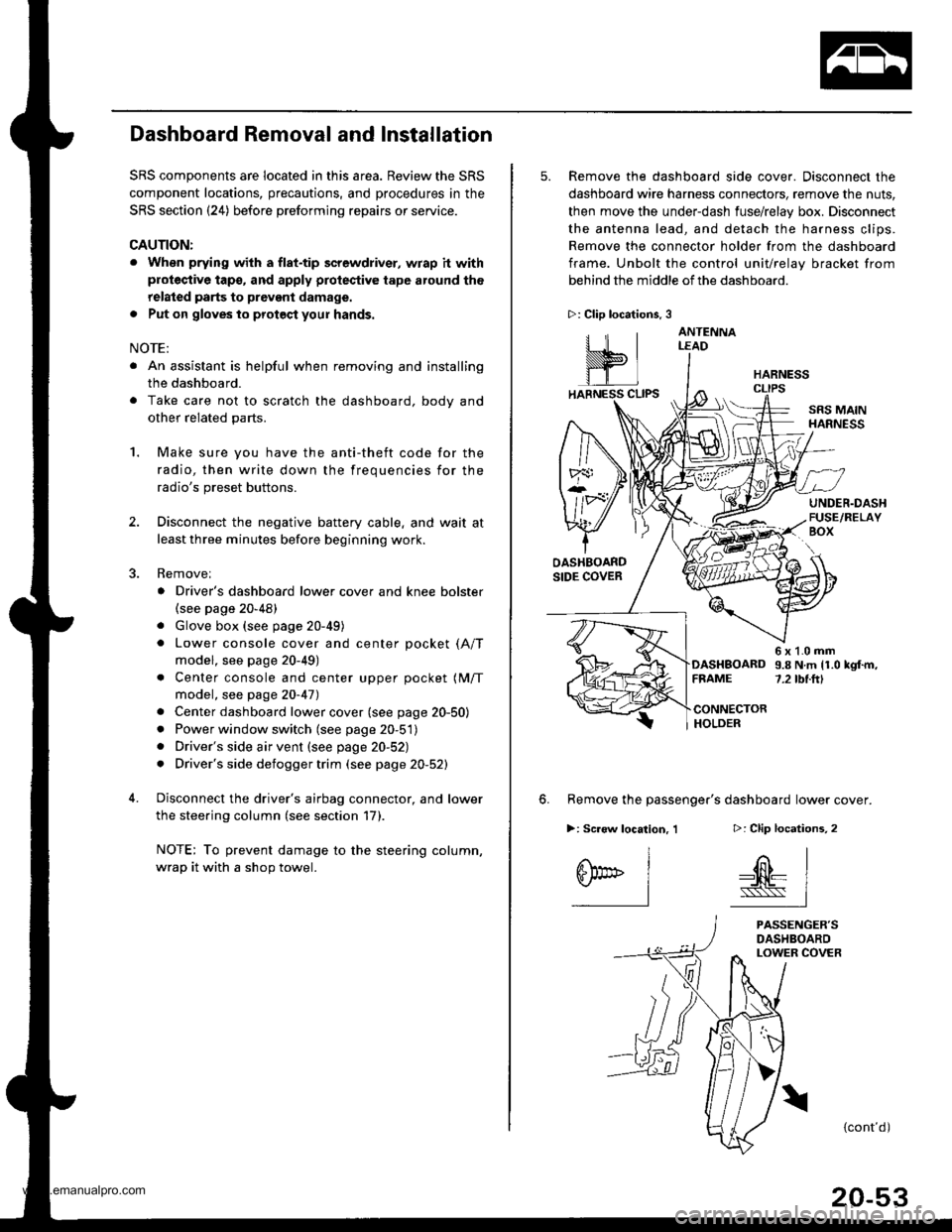
Dashboard Removal and Installation
SRS components are located in this area. Review the SRS
component locations, precautions, and procedures in the
SRS section {24) before preforming repairs or service.
CAUTION:
. When prying with a flat-tip screwdriver, wrap h withprotective tap€, and apply protective tape around the
related parts to prevgnt damage.
. Put on gloves to prot€ct your hands.
NOTE:
. An assistant is helpful when removing and installing
the dashboard.
. Take care not to scratch the dashboard, bodv and
other related parts.
1.Make sure you have the anti-theft code for the
radio, then write down the frequencies for the
radio's preset buttons.
Disconnect the negative battery cable. and wait at
least three minutes before beginning work.
Removei
a Driver's dashboard lower cover and knee bolster(see page 20-48)
. Glove box (see page 20-49)
. Lower console cover and center pocket (A/T
model, see page 20-49)
. Center console and center upper pocket (M/T
model, see page 20-47)
. Center dashboard lower cover (see page 20-50)
. Power window switch (see page 20-51)
. Driver's side air vent (see page 20-52)
. Driver's side defogger trim (see page 20-52)
Disconnect the driver's airbag connector, and lower
the steering column (see section 17)
NOTE: To prevent damage to the steering column,
wrap it with a shop towel.
2.
5. Remove the dashboard side cover. Disconnect the
dashboard wire harness connectors, remove the nuts,
then move the under-dash fuse/relay box. Disconnect
the antenna lead, and detach the harness clips.
Remove the connector holder from the dashboard
frame. Unbolt the control unit/relay bracket from
behind the middle of the dashboard.
HARNESS
6. Remove the passenger's dashboard lower cover.
D: Clip locations,
nl
-$t- Issj
I
ANTENNALEAD
>: Clip locations.
rttl
slllll
>: Scr€w location, 1
I
SF:oo I-l
SRS MAINHARNESS
UNDER.DASHFUSE/RELAYBOX
OASHBOARDSIDE COVER
6x1.0mm9.8Nm11.0kgf.m,7.2tbt.ftlDASHBOARDFFAME
CONNECTORHOLDER
PASSENGER'SDASHBOARDLOWER COVER
{cont'd)
www.emanualpro.com
Page 1035 of 1395
Dashboard
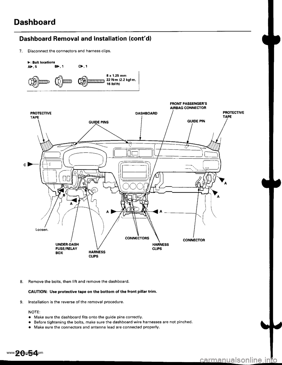
Dashboard Removal and Installation (cont'd)
7. Disconnect the connectors and harness cliDS.
>: Boli loc.lionsc>,1a>,5 B>,1
^5\h'.'_. 4fl\',r,' r$\'rmTrr' :j,1.ff,ry-r,.,".\fl)Prtu' W/* W)- tltbt.ttl
c)-
OASHBOARD
CONNECIORS
GUIDE PIN
CONNECTOR
Remove the bolts. then lift and remove the dashboard.
CAUTION: Use protective iape on the botlom of ths tront pillar trim.
lnstallation is the reverse of the removal procedure.
NOTE:
. Make sure the dashboard fits onto the guide pins correctly.
. Before tightening the bolts, make sure the dashboard wire harnesses are not pinched.
. Make sure the connectors and antenna lead are connected properly.
20-54
www.emanualpro.com
Page 1036 of 1395
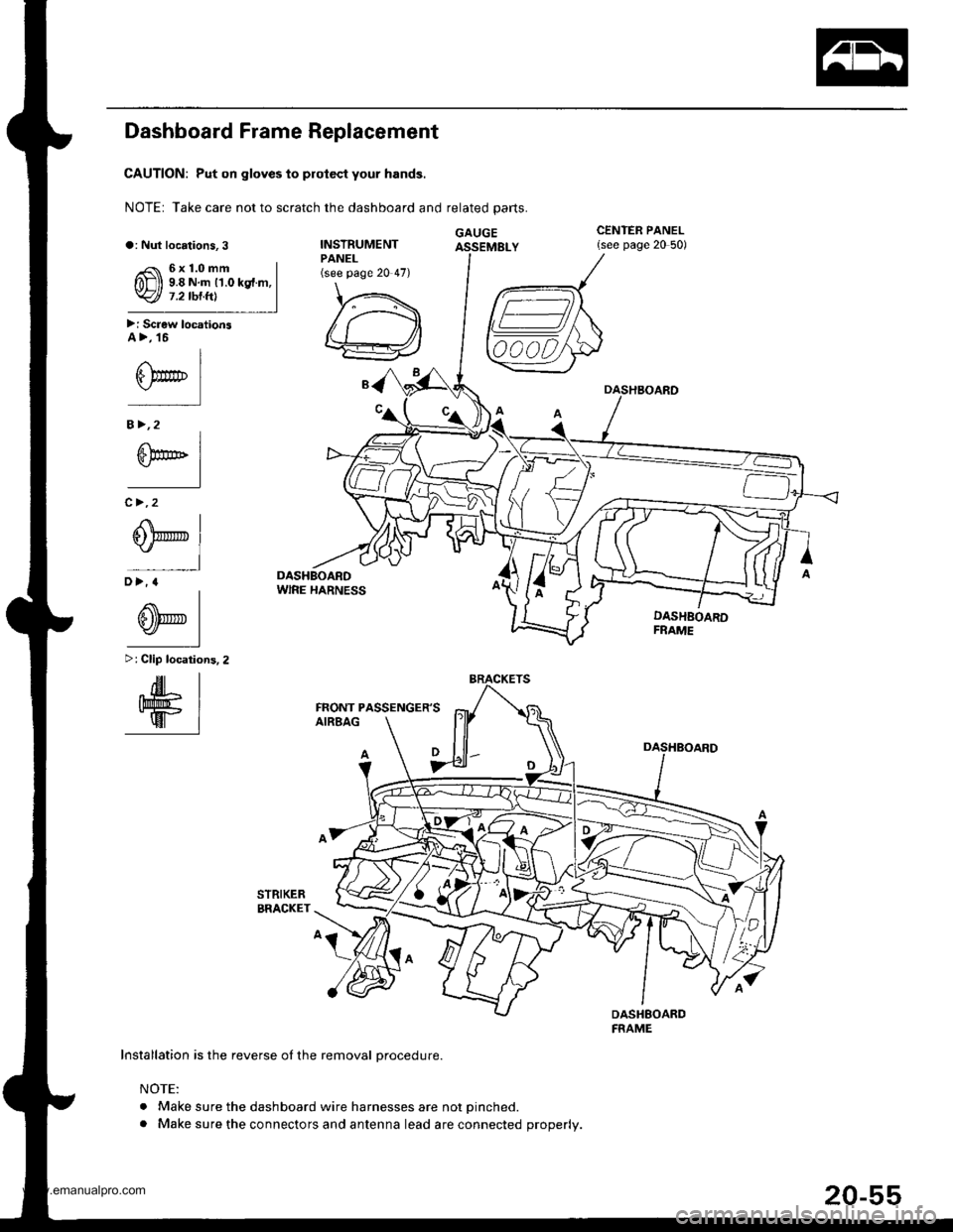
Dashboard Frame Replacement
CAUTION: Put on gloves to prolect your hands.
NOTE: Take care not to scratch the dashboard and related parts.
GAUGEa: Nut locations,3INSTRUMENTPANEL(see page 20 47)
\,.\
/ ,.-------f,\
lu /A
w
CENTER PANEL{see page 20 50)
6x1.0mm9.8 N.rn 11.0 kgf.m,7.2 tbt.ftl
>i Screw locationsA>,16
I
\,r*
B>,2
^l
S@t' 1-l
c >,2
I
0@l"l
D>.a
^l
0Fl-l
>: Clip localions.2
.dr IIhll'rifi- |-wr
i
DASHBOARDFRAME
DASHBOARDwlRE HARNESS
Installation is the reverse oI the removal orocedure.
NOTE:
. Make sure the dashboard wire harnesses are not Dinched.. Make sure the connectors and antenna lead are connected properly.
FRONT PASSENGER'S
www.emanualpro.com
Page 1041 of 1395
Seats
RECUNE ADJUSTER
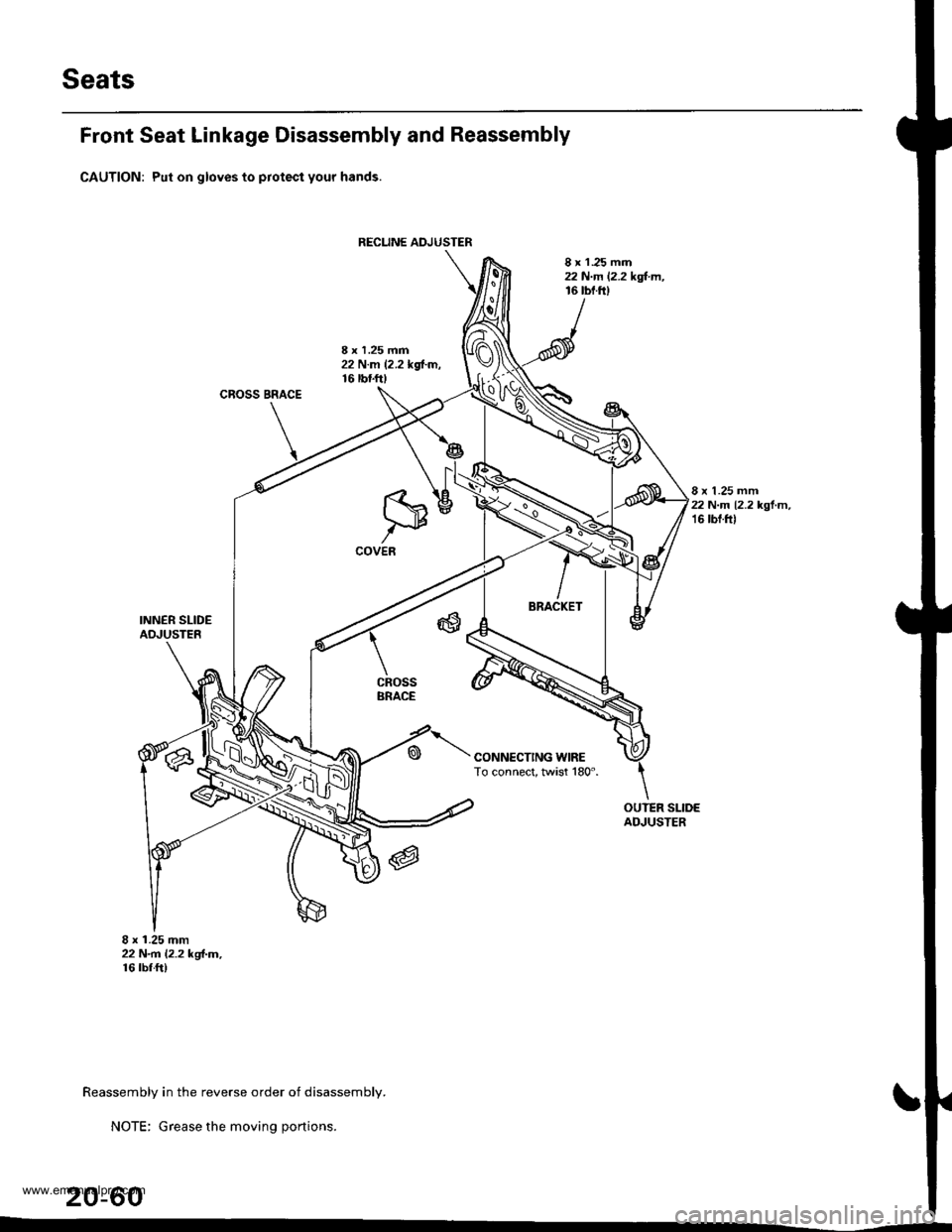
Front Seat Linkage Disassembly and Reassembly
CAUTION: Put on gloves to protect your hands.
8 x 1 .25 mm22 N.m 12.2 kgl.m,16 tbf.fi)
8 x 1.25 mm22 N.m 12.2 kd-m,16 tbtf0
CROSS BRACE
8 x 1.25 mm22 N.m 12.2 kgl.m,16 tbf.f0
INNER SLIDEADJUSTER
8 x 1.25 mm22 N.rn l.2.2 kgl-m,16 rbr.ft)
CONNECTING WIRETo connect, twist 180".
cRossBRACE
OUTER SLIDEAOJUSTER
Reassembly in the reverse order of disassembly.
NOTE: Grease the moving portions.
20-60
www.emanualpro.com
Page 1042 of 1395
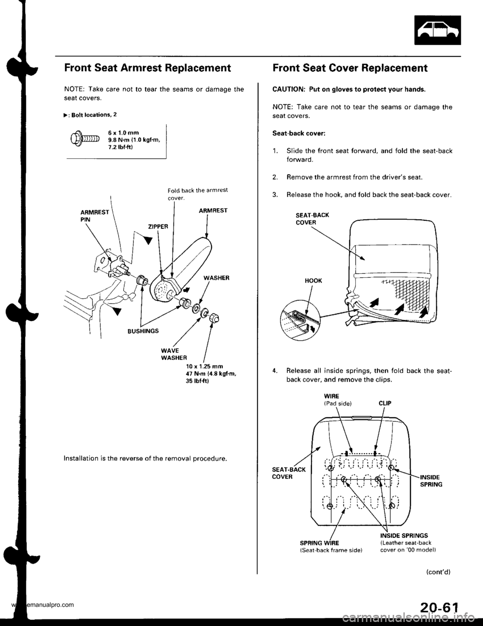
Front Seat Armrest Replacement
NOTE: Take care not to tear the seams or damage the
seat coverS.
>: Bolt locations.2
6r1.0mm9.8 N,m ll.0 kgl.m,7,2 tbf.ft)
10 x 1.25 mm47 N.m 1,1.8 kgf,m,35 tbt{t)
Installation is the reverse of the removal procedure.
Front Seat Cover Replacement
CAUTION: Put on gloves to protect your hands.
NOTE: Take care not to tear the seams or damage the
seat covers.
Seat-back cover:
'1. Slide the front seat forward, and fold the seat-back
forward.
2.
3.
Remove the armrest from the driver's seat.
Release the hook, and fold back the seat-back cover.
4.Release all inside springs, then fold back the seat-
back cover. and remove the clios.
WIRE{Pad sidei
(Seat back frame sjde) cover on '00 model)
(cont'd)
20-61
SEAT-BACK
www.emanualpro.com