srs HONDA CR-V 2000 RD1-RD3 / 1.G Owner's Guide
[x] Cancel search | Manufacturer: HONDA, Model Year: 2000, Model line: CR-V, Model: HONDA CR-V 2000 RD1-RD3 / 1.GPages: 1395, PDF Size: 35.62 MB
Page 1027 of 1395
![HONDA CR-V 2000 RD1-RD3 / 1.G Owners Guide
lnterior Trim
5.
Carpet Replacement (contdl
Remove the center lower cover (M/T model).
>: Clip locations,2
lN
-ffi]
6. Remove the SRS unit covers.
>: Clip locations,2
.dL ItEu( |- qf I cARPET
FASTE HONDA CR-V 2000 RD1-RD3 / 1.G Owners Guide
lnterior Trim
5.
Carpet Replacement (contdl
Remove the center lower cover (M/T model).
>: Clip locations,2
lN
-ffi]
6. Remove the SRS unit covers.
>: Clip locations,2
.dL ItEu( |- qf I cARPET
FASTE](/img/13/5778/w960_5778-1026.png)
lnterior Trim
5.
Carpet Replacement (cont'dl
Remove the center lower cover (M/T model).
>: Clip locations,2
lN'
-ffi]
6. Remove the SRS unit covers.
>: Clip locations,2
.dL ItEu( |- qf I cARPET
FASTENER('98 - 00 models)SNS UNIT
7. '97 model: Cut areas @ and @ in the carpet, then
pullthe carpet back.'98 - 00 models: Release the fastener and cut area
@ in the carpet, then pull the carpet back.
COVER
COVER
20-46
8. Remove the clips, and release the fasteners. then
remove the carpet.
NOTE: Take care not to damage, wrinkle or twist the
carpet.
>: Clip locations.3
FASTENER
lnstallation is the reverse of the removal procedure.
NOTE:
. Take care not to damage. wrinkle or twist the
carper.
. Make sure the seat harness is routed correctly.
. lf necessary, replace any damaged clips.
. Reaftach the cut areas @ and @ ('97 model) or
cut area @ ('98 - OO models) in the carpet with
wire ties.
www.emanualpro.com
Page 1029 of 1395
Dashboard
SRS components are located in this area. Review the SRS
component locations, precautions, and procedures in the
SRS section (24) before performing repairs or service.
GAUTION:
. When prying with a tlat-tip screwdriver, wrap h withproteqtive tape, and apply protective tape around the
relat€d parts, to prevent damage,
. Put on glovgs to protect your hands.
NOTE: Take care not to scratch the dashboard and relatedpans.
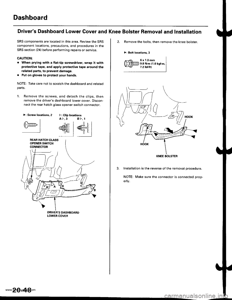
1. Remove the screws, and detach the clips, then
remove the driver's dashboard lower cover. Discon-
nect the rear hatch glass opener switch connector.
>: Clip locationsA >,3 B>, 1
rr.- | lr, l
@, | €{lr'" 1 |'l
>: Screw locations,2
IGlTtrrrb I.-l
REAR HATCH GLASSOPENER SWITCHCONNECTOR
20-48
'-
Driver's Dashboard Lower Cover and Knee Bolster Removal and Installation
2. Remove the bolts. then remove the knee bolster.
>: Boh locations,3
6x1.0mm9.8 N.m ('1.0 kgtm.7.2 tbtftl
3. Installation is the reverse of the removal procedure.
NOTE: Make sure the connector is connected prop-
erly.
KNEE BOLSTEF
www.emanualpro.com
Page 1031 of 1395
Dashboard
Center Dashboard Lower Gover
Removal and Installation
SRS components are located in this area. Review the SRS
component locations, precautions, and procedures in the
SRS section {24) before performing repairs or service
CAUTION:
. Wh€n prying with a flat-tip screwdrivet, wrap it with
protective tap€, and apply proteclive tape around the
rslated parts to prevenl damage.
. Put on glovgs to protect your hands.
NOTE: Take care not to scratch the dashboard and related
oarts.
1. Remove:
. Driver's dashboard lower cover (see page 20-48)
. Glove box (see page 20-49)
. Center pocket (AVT model. see page 20-49)
. Center console (M/f model, see page 20-41l,
. Center upper pocket (M/T model, see page 2O-47J
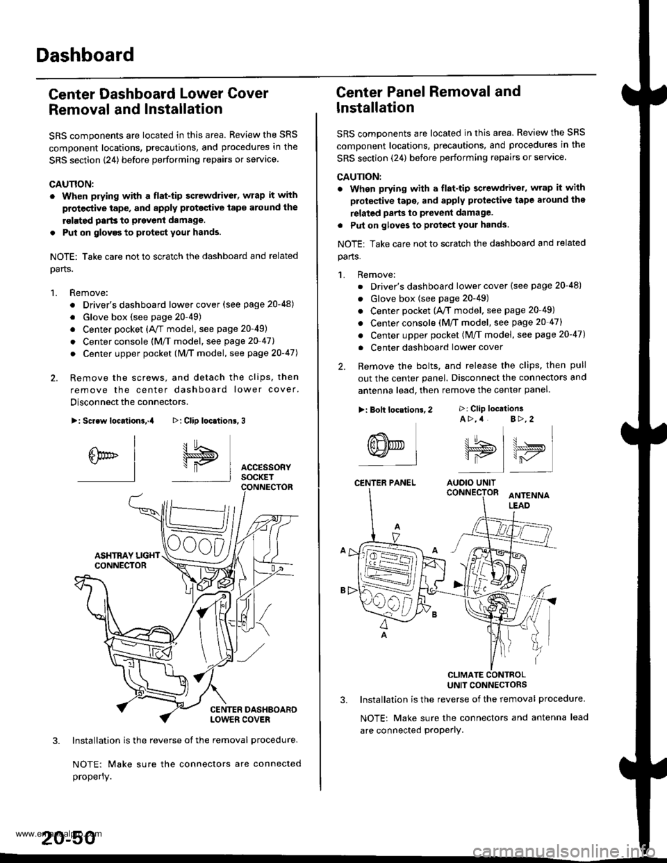
2. Remove the screws, and detach the clips. then
remove the center dashboard lower cover.
Disconnect the connectors.
>: Screw locationa,.a
I
6br" I-l
3. Installation is the reverse of the removal procedure-
NOTE: Make sure the connectors are connected
properly.
20-50
>: Clip loc.tion6,3
I5
\"P I AccEssoRyI socKET
Center Panel Removal and
lnstallation
SRS components are located in this area. Review the SRS
comDonent locations, precautions, and procedures in the
SRS section (24) before performing repairs or servace.
CAUTION:
. When prying with a flat-tip screwdriver, wrap it with
protective tape, and apply protective tape around the
relatgd parts to prevent damage.
. Put on gloves to protect your hands.
NOTE: Take care not to scratch the dashboard and related
parts.
1. Remove:
. Driver's dashboard lower cover (see page 20-48)
. Glove box (see page 20-49)
. Center pocket (A,/T model, see page 20-49)
. Center console (M/T model, see page 20-47)
. Center upper pocket {M/T model, see page 20-47)
. Center dashboard lower cover
2. Remove the bolts, and release the clips. then pull
out the center panel. Disconnect the connectors and
antenna lead. then remove the center panel.
CLIMATE CONTBOLUNIT CONNECTORS
3. Installation is the reverse of the removal procedure.
NOTE: Make sure the connectors and antenna lead
are connected proPerly.
>: Clip location3A >,4 B>,2
tt.t !^ t u . I\lJS>,, \>ryI is I r-,/'
AUOIO UNIT
>: Bolt locations,2
(8NED L-l
CENTER PANEL
www.emanualpro.com
Page 1034 of 1395
Dashboard Removal and Installation
SRS components are located in this area. Review the SRS
component locations, precautions, and procedures in the
SRS section {24) before preforming repairs or service.
CAUTION:
. When prying with a flat-tip screwdriver, wrap h withprotective tap€, and apply protective tape around the
related parts to prevgnt damage.
. Put on gloves to prot€ct your hands.
NOTE:
. An assistant is helpful when removing and installing
the dashboard.
. Take care not to scratch the dashboard, bodv and
other related parts.
1.Make sure you have the anti-theft code for the
radio, then write down the frequencies for the
radio's preset buttons.
Disconnect the negative battery cable. and wait at
least three minutes before beginning work.
Removei
a Driver's dashboard lower cover and knee bolster(see page 20-48)
. Glove box (see page 20-49)
. Lower console cover and center pocket (A/T
model, see page 20-49)
. Center console and center upper pocket (M/T
model, see page 20-47)
. Center dashboard lower cover (see page 20-50)
. Power window switch (see page 20-51)
. Driver's side air vent (see page 20-52)
. Driver's side defogger trim (see page 20-52)
Disconnect the driver's airbag connector, and lower
the steering column (see section 17)
NOTE: To prevent damage to the steering column,
wrap it with a shop towel.
2.
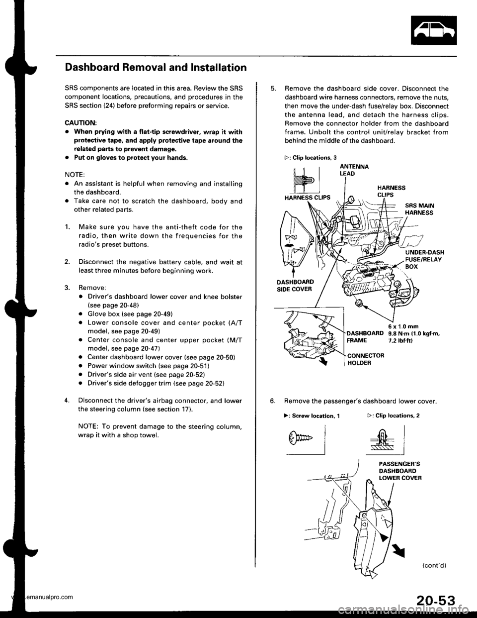
5. Remove the dashboard side cover. Disconnect the
dashboard wire harness connectors, remove the nuts,
then move the under-dash fuse/relay box. Disconnect
the antenna lead, and detach the harness clips.
Remove the connector holder from the dashboard
frame. Unbolt the control unit/relay bracket from
behind the middle of the dashboard.
HARNESS
6. Remove the passenger's dashboard lower cover.
D: Clip locations,
nl
-$t- Issj
I
ANTENNALEAD
>: Clip locations.
rttl
slllll
>: Scr€w location, 1
I
SF:oo I-l
SRS MAINHARNESS
UNDER.DASHFUSE/RELAYBOX
OASHBOARDSIDE COVER
6x1.0mm9.8Nm11.0kgf.m,7.2tbt.ftlDASHBOARDFFAME
CONNECTORHOLDER
PASSENGER'SDASHBOARDLOWER COVER
{cont'd)
www.emanualpro.com
Page 1090 of 1395
a
Heater and Air Conditioning
Heater ...........21
NOTE: Section 21 ("Heater") is included in section 22.
Air Conditioning ......'..'.. '.'22'1
SUPPLEMENTAL RESTRAINT SYSTEM (SRS}
This model has an SRS which includes a driver's airbag in the steering wheel hub, a passenger's airbag in the dashboard
above the glove box ('97,00 models). and seat belt tensioners in the seat belt retractors ('98 - 00 models). Information
necessary to safely service the SRS is included in this Service Manual. ltems marked with an asterisk (*) on the contents
page include. or are located near, SRS components. Servicing, disassembling or replacing these items will require special
precautions and tools, and should only be done by an authorized Honda dealer.
@. To avoid rendering the SRS inoperative, which could lead to personal iniury or death in the event of 8 severe frontal
collision, all SRS service work must be performed by an authotized Honda dealer.
lmproper service procedures, including incorrect removal and installation of the SRS, could lead to personal iniury
caused by unintentional deployment of the airbags ('97 - 00 models), and seat belt tensioners 138 - 00 models).
Do not bump the SRS unit. Otherwise, the system may fail in case of a collision, or the airbags may deploy when the
ignition switch is ON {lll.
SRS eleqtrical wiring harnesses are identified by yellow color coding. Related components are located in the steering
column, front console, dashboard, dashboard lower panel, and in the dashboard above the glove box. Do not use elec-
tricaltest equipment on thes€ cilcuils.
www.emanualpro.com
Page 1091 of 1395
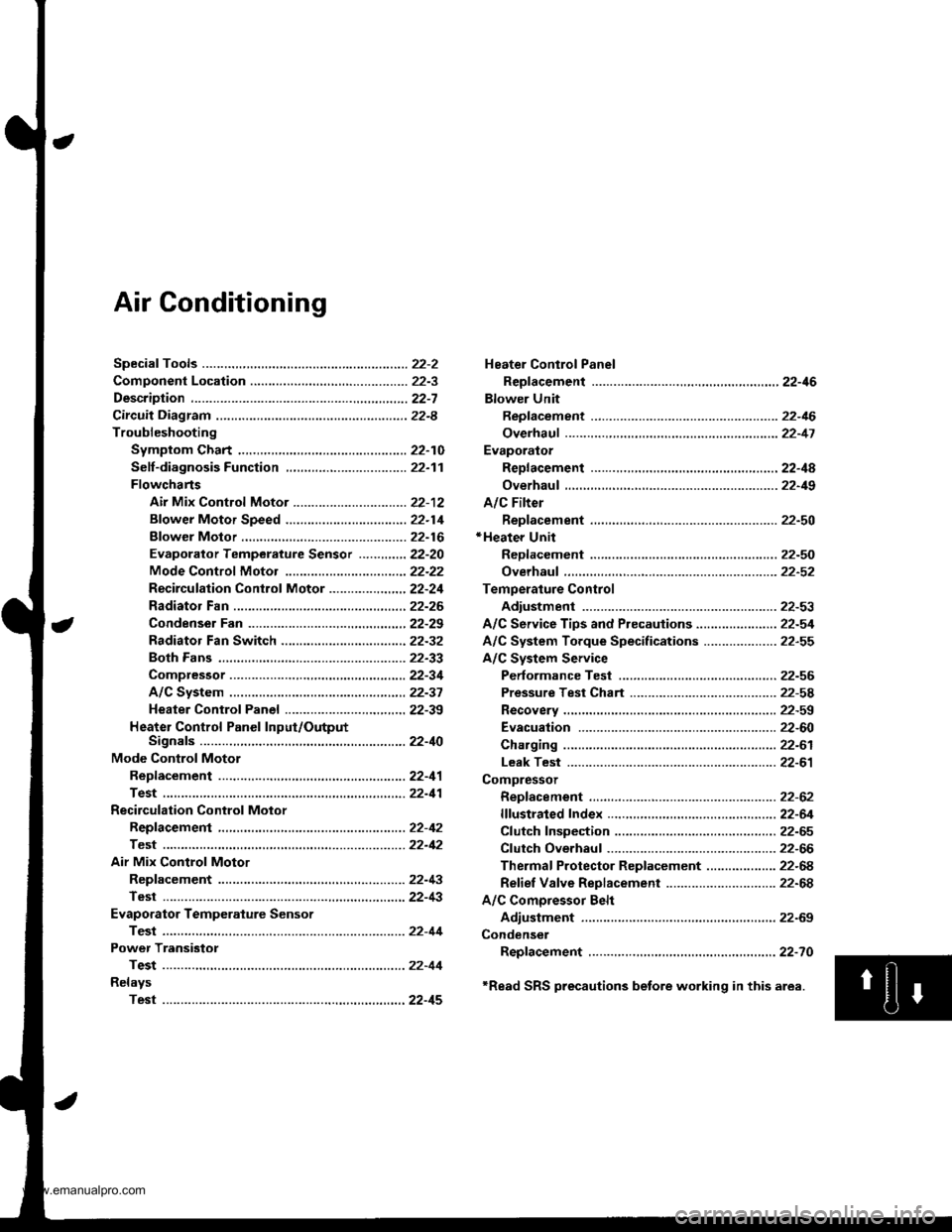
Air Conditioning
Heater Control Panel
Reofacement ,.,...,,.,..,.,.,,22-46
Blower Unit
Replacement .................. 22-46
Overhaul ...........,,,., .......-.22-17
Evaporalor
ReDlacement ...,.,.,..,......,22-4A
Overhaul ................ .........22-19
A/C Filter
Replacement ..................22-50*Heater Unit
ReDfacement ..................22-50
Overhaul ..,.,..,.,...,.. .........22-52
Temperature Control
Adiustment ....................22-53
A/C Service Tips and Precauiions............-....-.... 22-54
A/C System Torque Specifications .................... 22-55
A/C System Service
Performance Test ......,...22-56
Pressure Test Chart .-.....22-5a
Recovery ..............,. ...-.-...22-59
Evacuation -...........-........22-60
Charging ................ .......-.22-61
Leak Test ........................22-61
Compressor
Repfacement ..........-.......22-62
flfustrated Index .....,.......22-64
Cfutch fnspection .........,.22-65
Cfutch Overhaul ............- 22-66
Thermaf Protector Rep|acement ................... 22-68
Refief Valve Replacement .............................. 22-68
A/C Comoressor Belt
Adiustment .................... 22-69
Condenser
Repfacement .,.....,,.,..,.,..22-70
'Read SRS precautions betore working in this area.
www.emanualpro.com
Page 1094 of 1395
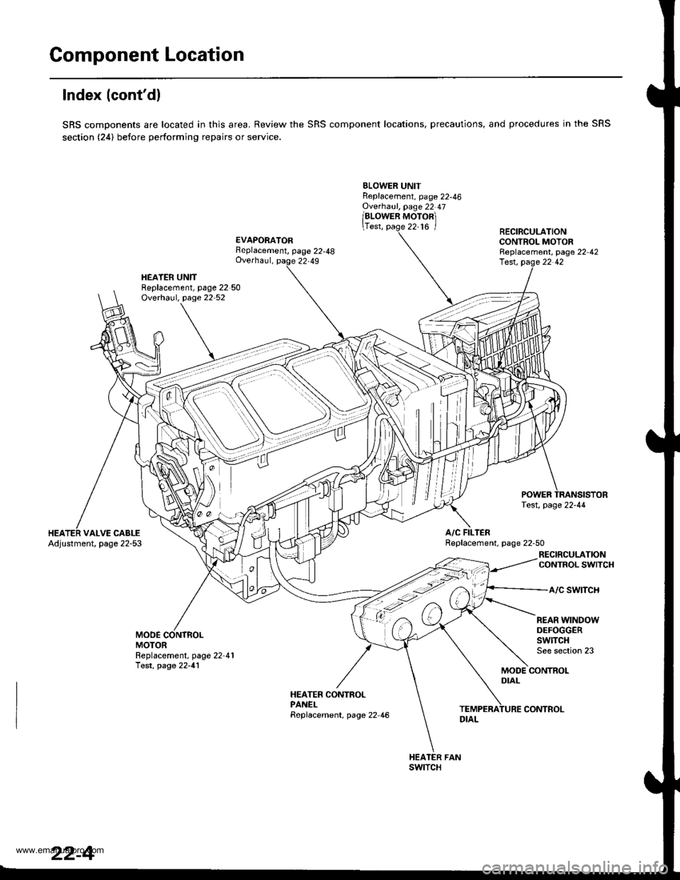
Component Location
lndex (cont'dl
SRS components are located in this area. Review the SRS component locations, precautions, and procedures in the SRS
section (24) before performing repairs or service.
BLOWER UNITReplacement, page 22-46Ovethaul, page 22 47
/alowen ruoronl
\Test, page 22-16 /
EVAPORATORFeplacement, page 22-48Overhaul, page 22,49
RECIRCULATIONCONTROL MOTORReplacement, page 22 42
HEATER UNITReplacement, page 22 50Overhaul, page 22 52
lest, pag.e 22 42
A/C FILIERReplacement. page 22-50VALVE CABLEAdjustment, page 22-53
RECIRCULATIONCONTROL SWITCH
a/c swtTcH
MODEMOTOR
REAR WINDOWDEFOGGERSwlTCHSee section 23Replacement, page 22-41Test, page 22-41MODE CONTROLDIAL
HEATER CONTROLPANELReplacement, page 22 46
swtTcH
22-4
CONTROL
www.emanualpro.com
Page 1096 of 1395
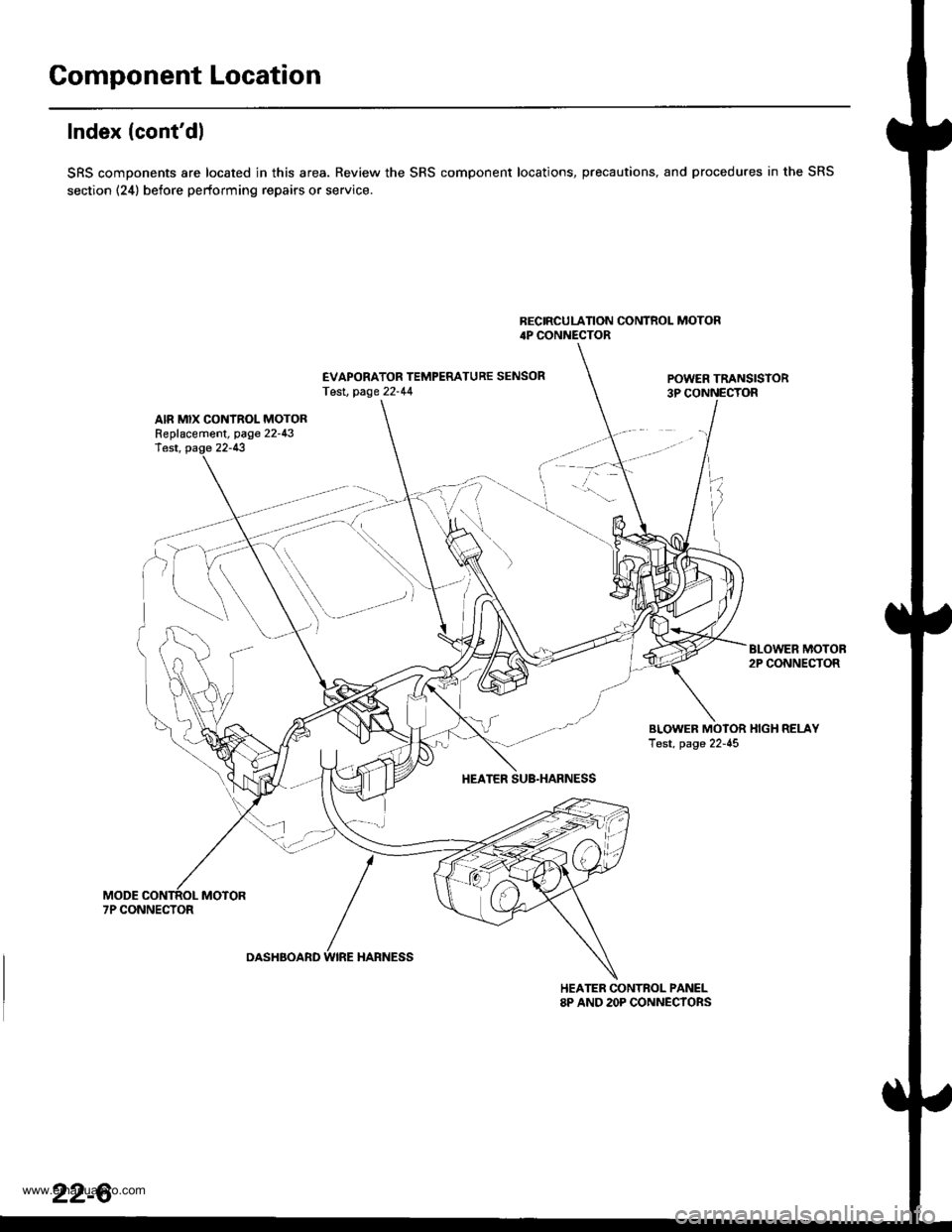
Component Location
Index (cont'dl
SRS components are located in this area. Review the SRS component locations, precautions, and procedures in the SRS
section (24) before performing repairs or service.
BECIRCULATION CONTROL MOTOR4P CONNECTOR
EVAPORATOR TEMPERATURE SENSORTesl, page 22-44POWER TRANSISTOR3P CONNECTOR
AIR MIX CONTROL MOTORReplacement, page 22-43lest, page 22-13
BLOWER MOTOB2P CONNECTOR
BLOWER MOTOR HIGH RELAYTest, page 22-45
HEATER SUB.HARNESS
7P CONNECTOR
DASHBOARD WIRE HARNESS
HEATER CONTROL PANEL8P AND 2OP CONNECYORS
22-6
www.emanualpro.com
Page 1140 of 1395
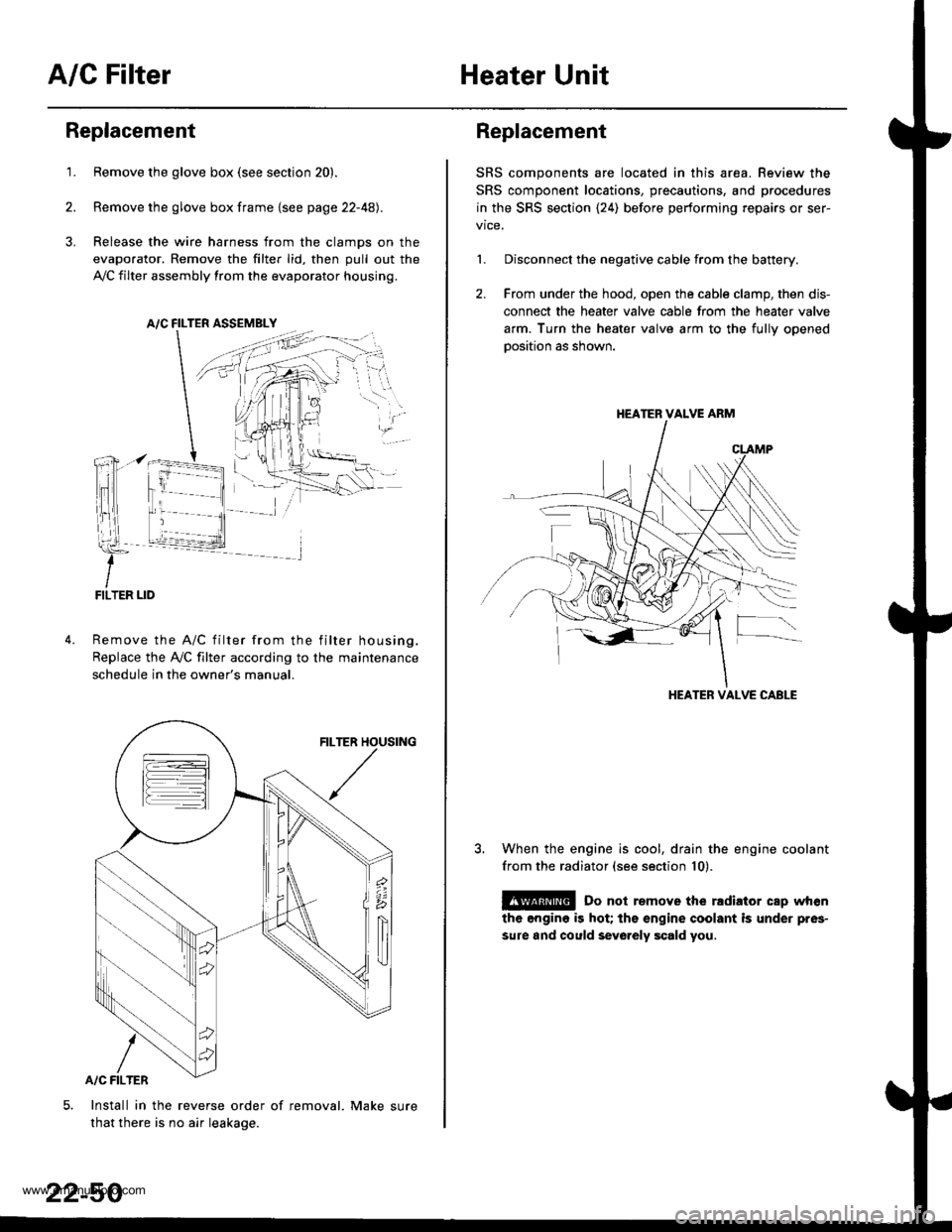
A/C FilterHeater Unit
Replacement
1.Remove the glove box (see section 20).
Remove the glove box frame {see page 22-4A).
Release the wire harness from the clamps on the
evaporator. Remove the filter lid, then pull out the
,VC filter assembly from the evaporator housing.
A/C FILTER ASSEMELY
Remove the A/C filter from the filter housing.
Replace the Ay'C filter according to the maintenance
schedule in the owner's manual.
Install in the reverse order of removal. Make sure
that there is no air leakage.
22-50
Replacement
SRS components are located in this area. Review the
SRS component locations, precautions, and procedures
in the SRS section {24) before performing repairs or ser-
1. Disconnect the negative cable from the battery.
2. From under the hood, open the cable clamp, then dis-
connect the heater valve cable from the heater valve
arm. Turn the heater valve arm to the fullv ooened
oosition as shown.
When the engine is cool, drain the engine coolant
from the radiator (see section 10).
@ Do not remove the rldiator cap when
the engine is hot; the engine coolant is under pres-
sure and could sevo.ely scald you.
HEATER VALVE ARM
HEATER VALVE CABLE
www.emanualpro.com
Page 1171 of 1395

Gonnector ldentification and Wire Harness Routing
How to ldentity Connectors:
ldentification numbers have been assigned to all connectors, The number is preceded by the letter "C" for connectors.
"G" for ground terminals or "T" for non-ground terminals.
Location
HarnessEngine CompartmsntDashboardOthers lFloor, Door,
8oof, Tailgate)
Starter cableT1, T2 and @
Battery ground cableG1 and O
Engine ground cableT3
Transmission ground cableT4
G3
Engine wire harnessC101 through C137
T101 and T102
G101
Engine compartment ware harnessC201 through C218
G201 and G202
Under-hood ABS fuse/relay box
wire harness
t5ano9
Main wire harnessC301 through C309
C351 through C361
C401 through C447
G401 and G402
Dashboard wire harnessC501 through C524 (C525)
G501
Left side wire harnessC551 through C581
G551, G552 and G553
Right side wire harnessC601 through C605
lnterior wire harnessC701 through C703
Rear bumper wire harnessC641 through C643
Heater sub-harnessC731 through C740
Secondary heated oxygen sensor
sub-harness
C721 through C722
Combination switch sub-harnessC751 through C760
Driver's door wire harnessC661 through C667
Front passenger's door wire harnessC6Tl through C676
Left rear door wire harnessC681 through C684
Right rear door wire harnessC69'l through C694
Rear wire harnessC611 through C520
Tailgate wire harnessC631 through C634
G631
SRS main harnessC801 through C808
G801
High mount brake light sub-harnessC651 through C653
Fuel tank oressure sensor sub-harnessC645 through C647
www.emanualpro.com