srs HONDA CR-V 2000 RD1-RD3 / 1.G Repair Manual
[x] Cancel search | Manufacturer: HONDA, Model Year: 2000, Model line: CR-V, Model: HONDA CR-V 2000 RD1-RD3 / 1.GPages: 1395, PDF Size: 35.62 MB
Page 1264 of 1395
Horns
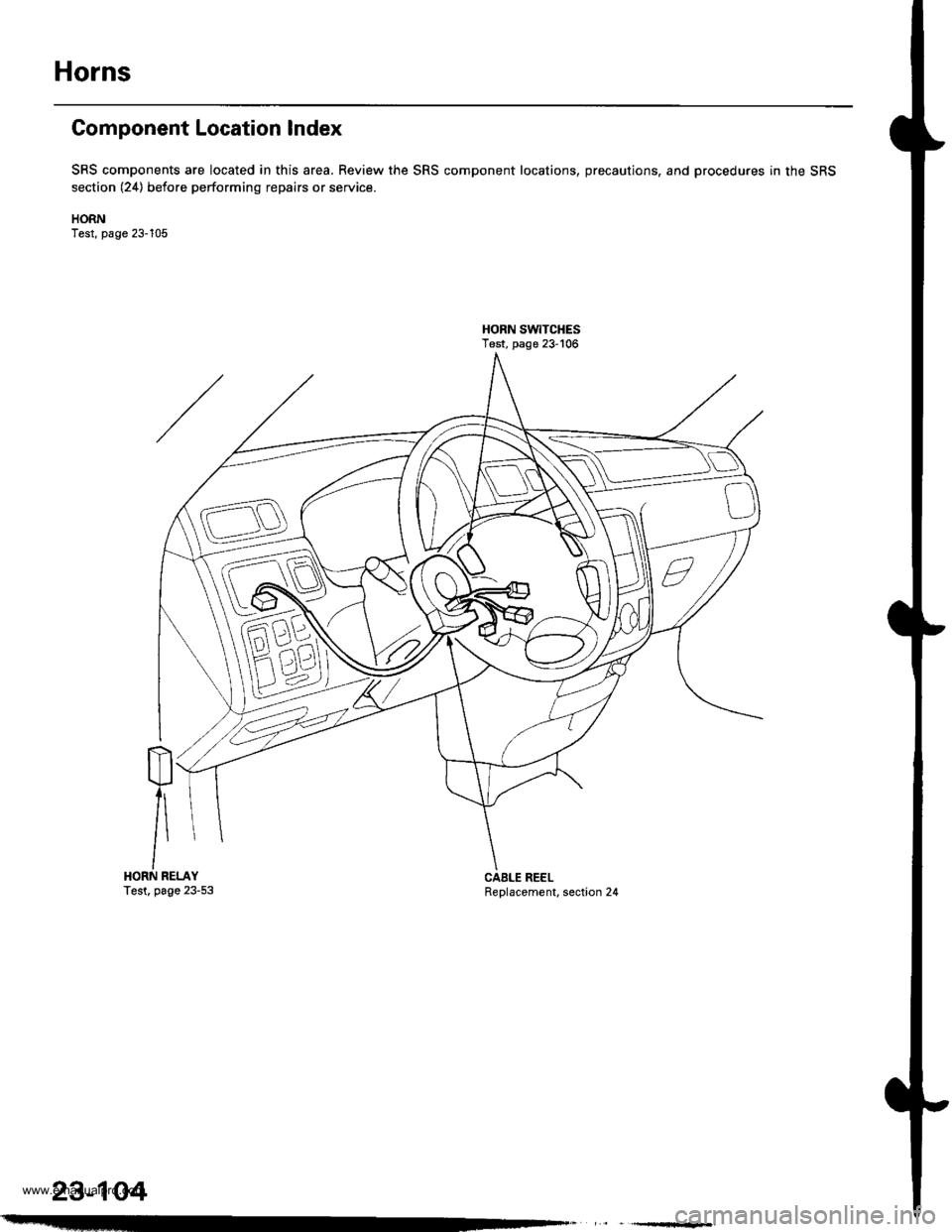
Component Location Index
SRS components are located in this area, Review the SRS component locations, precautions, and procedures in the SRS
section (24) before performing repairs or service.
HORNTest, page 23-105
HORN SW|TCHESTest, page 23-106
m
/\HORN RELAYTest. page 23-53Replacement, section 24CAELE REEL
23-104
www.emanualpro.com
Page 1266 of 1395
Horns
Switch Test
Disconnect the battery negative cable, then disconnect
the positive cable, and wait at ieastthree minutes.
Disconnect the driver's airbag and front passenger's
airbag connectors (see section 24).
Remove the drive.'s dashboard lower cover and the
knee bolster (see section 20).
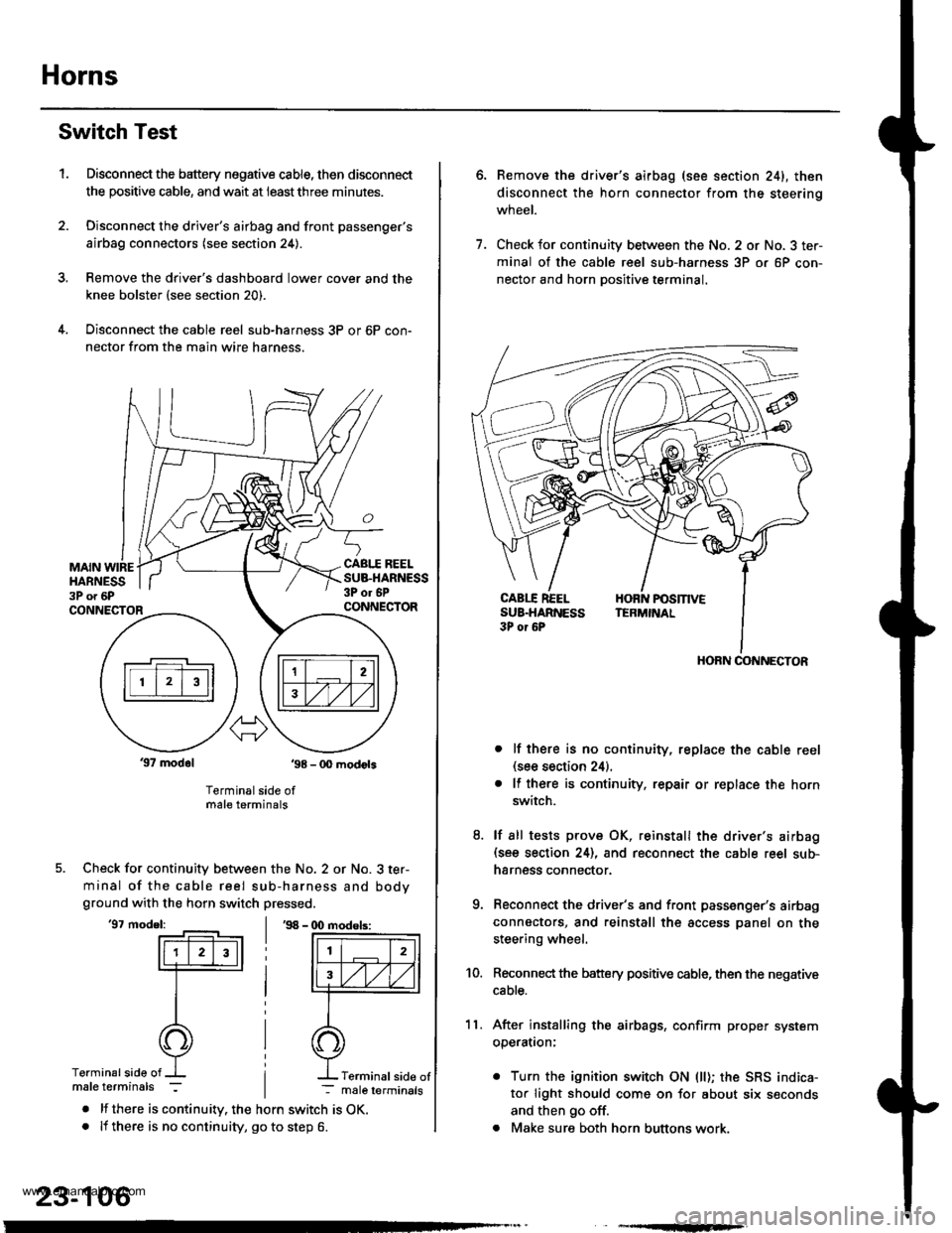
Disconnect the cable reel sub-harness 3P or 6P con-
nector from the main wire harness.
1.
MAIN WIREHARNESS3P o. 6P
CABI.I REELSUB.HARNESS3P or 6PCONNECTORCONNECTOR
37 modol ,98 - 0O modots
Terminal side ofmale terminals
Check for continuity between the No. 2 or No. 3 ter-
minal of the cable reel sub-harness and bodyground with the horn switch pressed.
'97 model:'98 - (X) modols:
Terminalside of
. lf there is continuity. the horn switch is OK.. lf there is no continuity, go to step 6.
23-106
Terminal side of
6.Remove the driver's airbag (see section 241, then
disconnect the horn connector from the steerinq
wneet.
Check for continuity between the No. 2 or No. 3 ter-
minal of the cable reel sub-harness 3P or 6P con-
nector and horn Dositive terminal.
lf there is no continuity, replace the cable reel(see section 24).
lf there is continuity. repair or replace the horn
switch.
lf sll tests prove OK, reinstall the driver's airbag(see section 24), and reconnect the cable reel sub-
harness connector.
Reconnect the driver's and front passenger's airbag
connectors, and reinstall the access panel on the
steering wheel.
Reconnect the battery positive cable, then the negative
cable.
After installing the airbags, confirm proper system
operatron:
. Turn the ignition switch ON (ll); the SRS indica-
tor light should come on for about six seconds
and then go off.
. Make sure both horn buttons work.
7.
11.
8.
9.
10.
HORN CONNECTOR
www.emanualpro.com
Page 1274 of 1395
Wipers/Washers
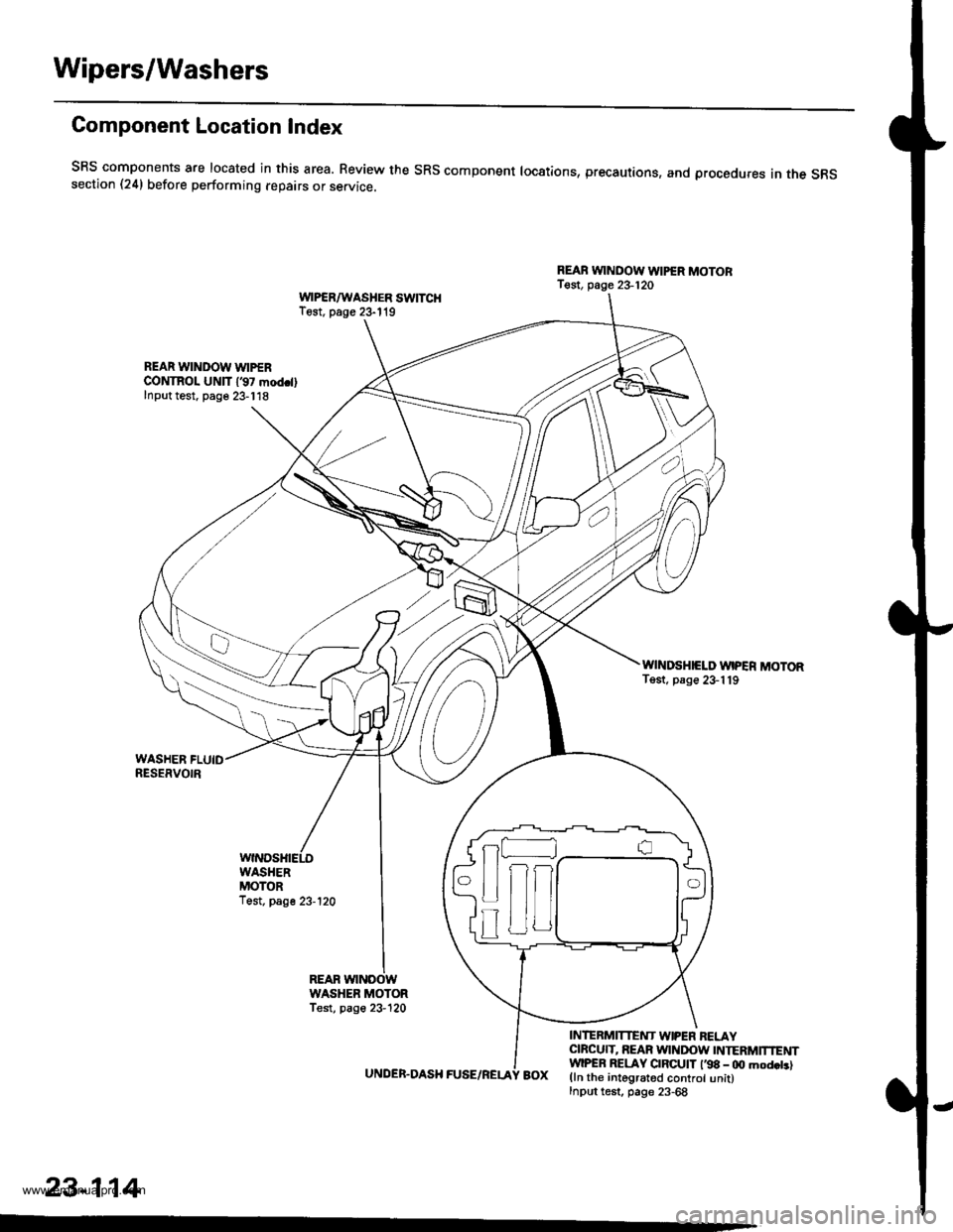
Component Location Index
SRS components are located in this area. Review the SRs component locations, precautions, and procedures in the s6ssection (24) before performing repairs or service.
REAB WINDOW WIPER MOTOBT€st, page 23-120WPSR/WASHER SWITCHTest. page 23- l't9
REAR WINDOW WIPERCONTROL UNlT 137 mod.llInput test. page 23-118
WINDSHIELD WIPER MOTORTost, page 23-119
UNDER.DASH FUSE/RELA
INTERMITTENT W|PEN RELAYCIBCUIT, REAR WINDOW INTERMTNENTwlPER RELAY CIBCUIT l'98 - 0O mod.t.lBOX (ln the integrated control unit)Input test, page 23-68
23-114
-
n
tff
www.emanualpro.com
Page 1299 of 1395
IJ
Restraints
Seat Belts .....24-1
Supplemental Restraint SYstem
(sRSl ......'.'. ""'.""".""""24-13
Seat Belts
Component Location Index .'."..'..'-'.' 24'2
Front Seat Belt Replacement '......"'.. 24-3
Rear Seat Belt Replacement ......'.". '.' 24-6
f, - lnspection .....""""""""' 24-9
Child Seat Tether Anchor
lnstallation -'97 - 99 Models ."'."24-10
Child Seat Tether Anchor
Removal/lnstallation
-'00 Model ....'......'.'....'.'.."-'-'."' 24'11
l-
www.emanualpro.com
Page 1300 of 1395
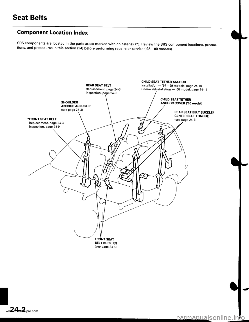
Seat Belts
Component Location Index
SRS components are located in the parts areas marked with an asterisk {*). Review the SRS component locauons, precau-tions, and procedures in this section (24) before performing repairs or service (,98 _ 00 models).
CHILD SEAT TETHEN ANCHORlnstallation -'97 99 models, page 24-10Removal/lnstallation - '00 model, page 24-11
CHILD SEAT TETHERANCHOR COVER ('00 mod€tl
REAR SEAT BELT BUCKLE/CENTER BELT TONGUE(see page 24-7).FRONT SEAT BELTReplacement, page 24 3Inspection, page 24-9
BELT EUCKLES(see page 24 5)
24-2
,--.4
www.emanualpro.com
Page 1301 of 1395
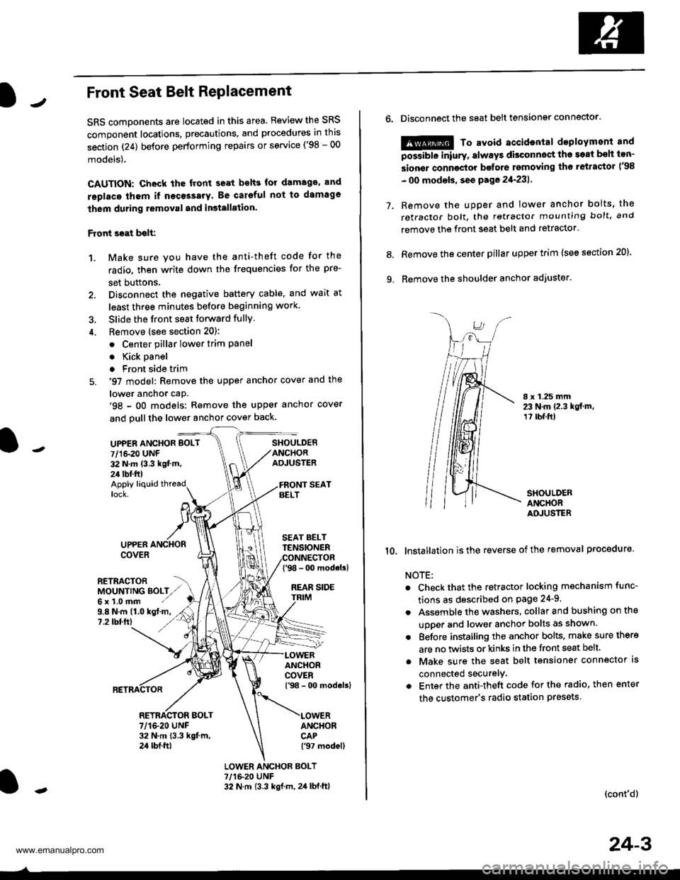
JFront Seat Belt RePlacement
SRS components are located in this area. Review the SRS
component locations, precautions, and procedures in this
section (24) before performing repairs or service ('98 - 00
models).
CAUTION: Check the front seat bslts for damago. and
replaco thom if necessary. Be careful not to damage
them during removal and in3tallation'
Front scat bolt:
1. Make sure you have the anti-theft code for the
radio, then write down the frequencies for the pre-
set buttons.
2. Disconnect the negative battery cable, and wait at
least three minutes before beginning work.
3. Slide the front seat forward fully.
4. Bemove (see section 20):
. Center pillar lower trim Pane
. Kick oanel
. Front side trim
5. '97 model: Remove the upper anchor cover and the
lower anchor caP.'98 - oO models: Remove the upper anchor cover
and pull the lower anchor cover back.
UPPEN ANCHOR BOLT
7/1&20 UNF32 N.m (3.3 kgt'm.24 tbf.ft)
SHOULDERANCHORADJUSTER
Apply liquid threadlock.
9.8 N.m (1.0 kgt.m,?.2 tbtft)
UPPERCOVER
RETRACTORMOUNTING BOLTZ,,Gx1.0mm ./
SEAT BELTTENSIONER
{'98 - 0o modols)
REAR SIDE
ANCHORCOVERl'98 - 00 models)
ANCHORCAP('97 modell
RETRACTOR BOLT7/1&20 UNF32 N.m 13.3 kgt m,24 tbt.ft)
LOWER ANCHOR BOLT?,/1&20 UNF32 N.m {3.3 kgf.m, 2,1 lbf.ftl
o.Disconnect the seat belt tensiongr connector.
@ To avoid accidontal deployment and
possibte inlury, always disconnect the soat bsh ton-
sion€r connoctor bofore rsmoving th6 retractor l'98
- 00 modsls, se€ pa ge 21-231 .
Remove the uDDer and lower anchor boits, the
retractor bolt, the retractor mounting bolt, and
remove the front seat belt and retractor.
Remove the center pillar upper trim (see section 20).
Remove the shoulder anchor adjuster.
7.
9.
8.
I x 1.25 mm23 N.m 12.3 kgt.m,1? tbf.ft)
SHOULDERANCHORADJUSTER
10. lnstallation isthe reverse of the removal procedure.
NOTE:
Check that the retractor locking mechanism func-
tions as described on Page 24-9.
Assemble the washers, collar and bushing on the
uooer and lower anchor bolts as shown.
Eefore installing the anchor bolts, make sure there
are no twists or kinks in the front seat belt.
Make sure the seat belt tensioner connector ls
connected securelv.
Enter the anti-theft code for the radio, then enter
the customer's radio station presets
(cont'd)
24-3
www.emanualpro.com
Page 1307 of 1395
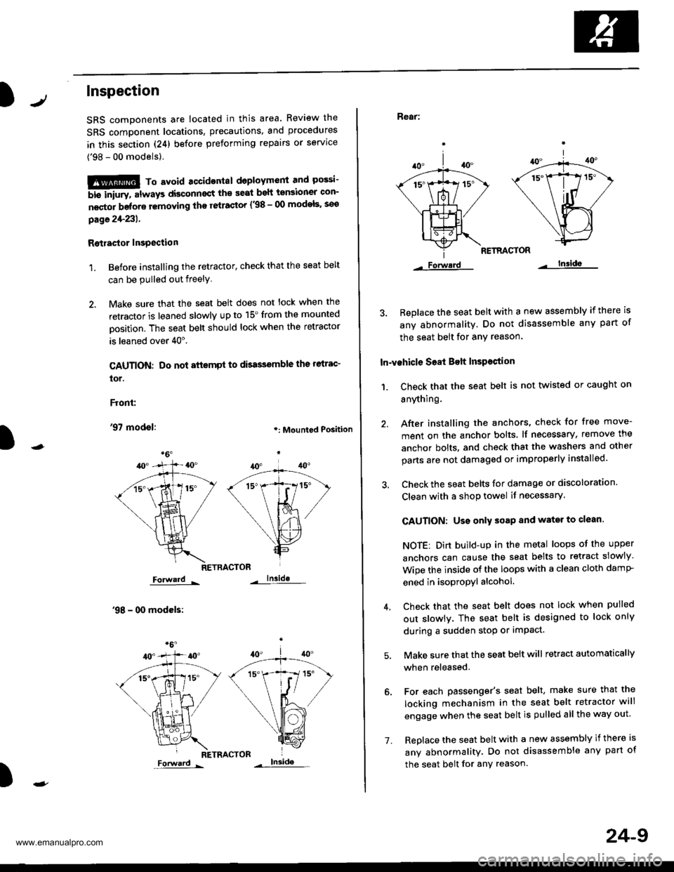
Inspection
SRS components ale located in this area. Review the
SRS component locations, precautions, and procedures
in this section (24) before preforming repairs or service
('98 - 00 models).
!!!@ To avoid accidontal deployment and possi-
6i6-'rnpry. att"ays aisconnsct th€ seat beh tensioner con-
n€ctor belore removing tho retrastor {.98 - 00 modols, seo
page2+231.
Rgtlastor Insgection
1. Before installing the retactor, check that the seat belt
can be pulled out freely
2. Make sure that the seat belt does not lock when the
retractor is leaned slowly up to 15'from the mounted
Dosition. The seat belt should lock when the retractor
is leaned over 40".
CAUTION: Do not attsmpt to dbassemble ths relrac'
tor.
Front:
'97 modol:.: Mounted Position
RETRACTOR
Forward -
'98 - 00 modcls:
lnside
RETRACTOR
)
Forward -
'1.
24-9
Rear:
RETRACTOR
Forwerd lnsida
3. Beplace the seat belt with a new assembly if there is
any abnormality. Do not disassemble any part of
the seat belt for any reason.
In-vehicle S68t Belt InsPestion
1. Ch€ck that the seat belt is not twisted or caught on
anything.
40.
/A
\|_t-.
*1ix
\/
Lls=
Forwerd
After installing the anchors, check for free move-
ment on the anchor bolts lf necessary, remove the
anchor bolts, and check that the washers and other
parts are not damaged or improperly installed.
Check the seat belts for damage or discoloration.
Clean with a shop towel if necessary.
CAUTION: Uso only soap and wator to clean.
NOTE: Dirt build-up in the metal loops of the upper
anchors can cause the seat belts to retract slowly
Wipe the inside of the loops with a clean cloth damP
ened in isopropyl alcohol.
Check that the seat belt does not lock when pulled
out slowlv. The seat belt is designed to lock only
during a sudden stop or impact.
Make sure that the seat belt will retract automatically
when released.
For each passenger's seat belt, make sure that the
locking mechanism in the seat belt retractor will
engage when the seat belt is pulled all the way out.
Replace the seat belt with a new assembly if there is
any abnormality. Do not disassemble any part of
the seat belt for any reason.
www.emanualpro.com
Page 1310 of 1395
)
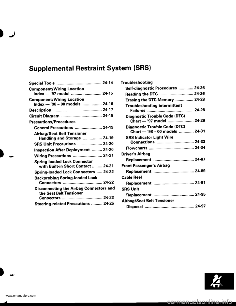
Supplemental Restraint System (SRS)
Special Tools .."....."" 24-14
Component/Wring Location
lndex - '97 model ..........'.." '.....""" 24-15
Component/Wiring Location
lndex - '98 - 00 models ..............." 24-16
Description .'.........."'.24'17
Circuit Diagram .........24'14
Precautions/Procedures
General Precautions ......".."'........... 24-19
Airbag/Seat Belt Tensioner
Handling and Stolage ....''........... 24-19
SRS Unit Precautions ...............'...... 24-20
lnspeciion After Deployment .......'.24'20
)
with Built-in Short Contact '...'....24-21
Spring-loaded Lock Connectors .."' 24-22
BackProbing SPring-loaded Lock
Conneetors ,.......24-22
Disconnecting the Airbag Connectors and
the Seat Beh Tensioner
Connectors ....'....24-23
Steering-lelated Precautions .......... 24-25
Troubleshooting
Self -diagnostic Procedures ............. 24-26
Reading the DTC .................. .....".."' 24'26
Erasing the DTC Memory ................24-28
Troubleshooting lntermittent
Faifures "'...........24'24
Diagnostic Trouble Gode {DTC}
Chart -'97 model ....""....... "......24-29
Diagnostic Trouble Gode (DTCI
Chart -'98 - 00 models ............. 24-31
SRS Indicator Light Wire
Connections ','," 24'33
Ff owcharts ....-........24'34
Driver's Airbag
Repf acement ..'......21'87
Front Passenger's Airbag
Repfacement .....'.',24'AS
Gable Reel
Replacement .......'.24-91
SRS Unit
Replacement .........24-95
Airbag/Seat Belt Tensioner
Disposaf .................24'97
)-e
www.emanualpro.com
Page 1311 of 1395
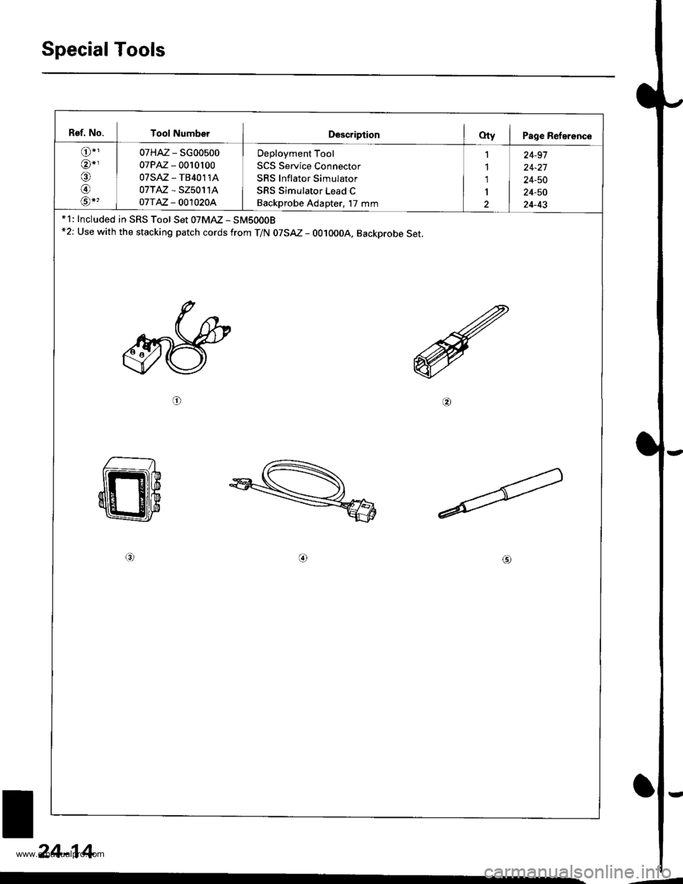
Special Tools
Ref. No. Tool NumberDescriptionOty I Page Reference
o"'
@-,/a\
@rA*,
07HAz - SG00500
07PM - 0010100
07sAz - TB40114
07TAZ - SZ50114
o7T AZ - OO1O20A
Deployment Tool
SCS Service Connector
SRS Inflator Simulator
SRS Simulator Lead C
Backprobe Adapter, l7 mm
1
1'1
I
2
24-91
24-21
24-50
24-50
24-43* 1: Included in SRS Tool Set 07MAZ - SM5000B*2: Use with the stacking patch cords from T/N 07SAZ - 0010004, Backprobe Set.
o@
/no
24-14
.-
www.emanualpro.com
Page 1312 of 1395
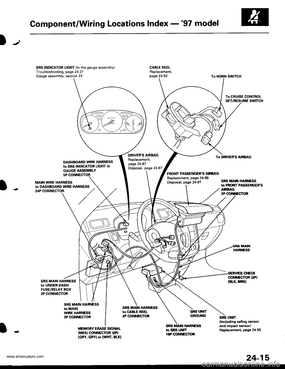
Component/Wiring Locations Index -'97 model
SRS INDICATOR LIGHT (ln the gauge assembly)Troubleshooting, page 24-27Gauge assembly, section 23
DASHBOABD w|RE HARNESS
to SBS INDICATOR LIGHT in
DRIVER'S AIBMGReplacement,page 21-87Disposal, page 24-97
To CRUISE CONTROLSET
To DRIVERS AnBAG
ANBAG2P
sBsitAr[ ] nNEssto FROI|T PASSEiIGEB.S
FRONT PASSEITGER'S AIRBAGReplacement, pago 24{9Disposal, page 24-97
sns ut{fTGROUND
SES MAIN HAR]GSStosns U nItP OOIIITECTOR
MAIN WIRE HABNESSto DASHBOABD wlRE21P
SRS MAIN HABNESSto UNOEB-DASHFUSE/BELAY BOX2P CONNECTOR
GOf$ECrOn PPIlBLr( 8R t
MEMORY ERASE SIGNALIMES) CONNECTOR I2PI[GRY. GRYI or twHT, BLr.l
GAUGE ASSEMBLY5P
HARNESS
SRS MAIN HARNESSto MAINWIRE HARNESS3P OONNECTOR
24-15
www.emanualpro.com