HONDA CR-V 2015 RM1, RM3, RM4 / 4.G Owners Manual
Manufacturer: HONDA, Model Year: 2015, Model line: CR-V, Model: HONDA CR-V 2015 RM1, RM3, RM4 / 4.GPages: 533, PDF Size: 24.82 MB
Page 501 of 533
500
uuIndicator, Coming On/Blinking uIf the Malfunction Indicato r Lamp Comes On or Blinks
Handling the Unexpected
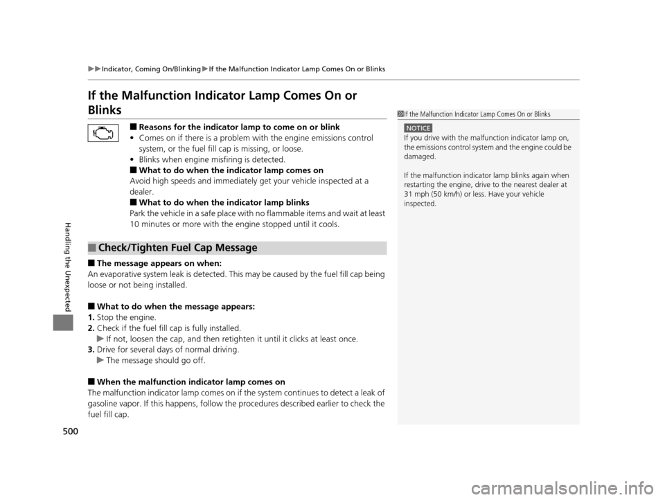
If the Malfunction Indicator Lamp Comes On or
Blinks
■Reasons for the indicator la mp to come on or blink
• Comes on if there is a problem wi th the engine emissions control
system, or the fuel fill cap is missing, or loose.
• Blinks when engine misfiring is detected.
■What to do when the indicator lamp comes on
Avoid high speeds and immediately get your vehicle inspected at a
dealer.
■What to do when the indicator lamp blinks
Park the vehicle in a safe place with no flammable items and wait at least
10 minutes or more with the engine stopped until it cools.
■The message appears on when:
An evaporative system leak is detected. This may be caused by the fuel fill cap being
loose or not being installed.
■What to do when the message appears:
1. Stop the engine.
2. Check if the fuel fill cap is fully installed.
u If not, loosen the cap, and then reti ghten it until it clicks at least once.
3. Drive for several days of normal driving.
u The message should go off.
■When the malfunction indicator lamp comes on
The malfunction indicator lamp comes on if the system continues to detect a leak of
gasoline vapor. If this happens, follow th e procedures described earlier to check the
fuel fill cap.
■Check/Tighten Fuel Cap Message
1 If the Malfunction Indicato r Lamp Comes On or Blinks
NOTICE
If you drive with the malf unction indicator lamp on,
the emissions control system and the engine could be
damaged.
If the malfunction indicator lamp blinks again when
restarting the engine, drive to the nearest dealer at
31 mph (50 km/h) or less. Have your vehicle
inspected.
15 CR-V-31T0A6300.book 500 ページ 2015年2月2日 月曜日 午前10時35分
Page 502 of 533
501
uuIndicator, Comin g On/BlinkinguIf the Brake System Indicator (Red) Comes On
Handling the Unexpected
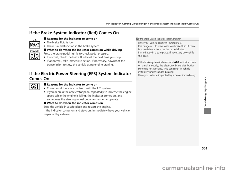
If the Brake System Indicator (Red) Comes On
■Reasons for the indicator to come on
• The brake fluid is low.
• There is a malfunction in the brake system.
■What to do when the indica tor comes on while driving
Press the brake pedal lightly to check pedal pressure.
• If normal, check the brake fluid level the next time you stop.
• If abnormal, take immediate acti on. If necessary, downshift the
transmission to slow the vehicle using engine braking.
If the Electric Power Steeri ng (EPS) System Indicator
Comes On
■Reasons for the indicator to come on
• Comes on if there is a problem with the EPS system.
• If you depress the accelerator pedal repeatedly to increase the engine
speed while the engine is idling, the indicator comes on, and
sometimes the steering wheel becomes harder to operate.
■What to do when th e indicator comes on
Stop the vehicle in a safe place and restart the engine.
If the indicator comes on and stays on, immediately have your vehicle
inspected by a dealer.
1 If the Brake System Indicator (Red) Comes On
Have your vehicle re paired immediately.
It is dangerous to drive with low brake fluid. If there
is no resistance from the brake pedal, stop
immediately in a safe plac e. If necessary downshift
the gears.
If the brake system indicator and ABS indicator come
on simultaneously, the elec tronic brake distribution
system is not working. Th is can result in vehicle
instability under sudden braking.
Have your vehicle inspecte d by a dealer immediately.U.S.
Canada
15 CR-V-31T0A6300.book 501 ページ 2015年2月2日 月曜日 午前10時35分
Page 503 of 533
502
uuIndicator, Coming On/Blinking uIf the Low Tire Pressure/TPMS Indicator Comes On or Blinks
Handling the Unexpected
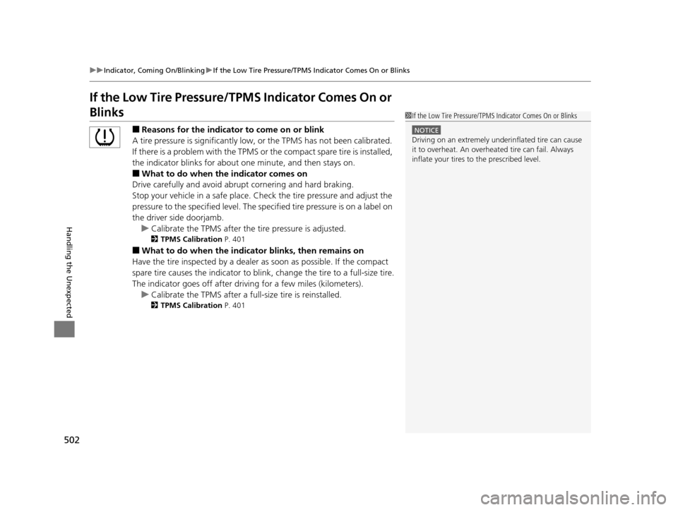
If the Low Tire Pressure/TPMS Indicator Comes On or
Blinks
■Reasons for the indicator to come on or blink
A tire pressure is signifi cantly low, or the TPMS has not been calibrated.
If there is a problem with the TPMS or the compact spare tire is installed,
the indicator blinks for about one minute, and then stays on.
■What to do when the indicator comes on
Drive carefully and avoid abrupt cornering and hard braking.
Stop your vehicle in a safe place. Ch eck the tire pressure and adjust the
pressure to the specified level. The sp ecified tire pressure is on a label on
the driver side doorjamb.
u Calibrate the TPMS after the tire pressure is adjusted.
2 TPMS Calibration P. 401
■What to do when the indicator blinks, then remains on
Have the tire inspected by a dealer as soon as possible. If the compact
spare tire causes the indicator to blink, change the tire to a full-size tire.
The indicator goes off after driv ing for a few miles (kilometers).
u Calibrate the TPMS after a full-size tire is reinstalled.
2 TPMS Calibration P. 401
1If the Low Tire Pressure/TPMS Indicator Comes On or Blinks
NOTICE
Driving on an extremely unde rinflated tire can cause
it to overheat. An overheated tire can fail. Always
inflate your tires to the prescribed level.
15 CR-V-31T0A6300.book 502 ページ 2015年2月2日 月曜日 午前10時35分
Page 504 of 533
503Continued
Handling the Unexpected
Fuses
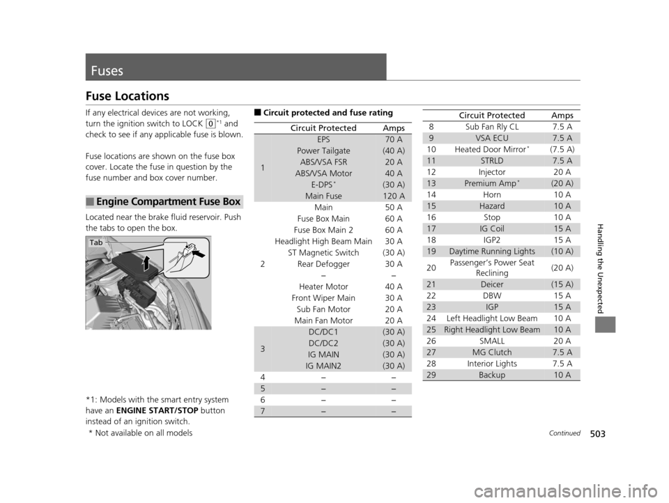
Fuse Locations
If any electrical devices are not working,
turn the ignition switch to LOCK
(0*1 and
check to see if any appl icable fuse is blown.
Fuse locations are shown on the fuse box
cover. Locate the fuse in question by the
fuse number and box cover number.
Located near the brake fluid reservoir. Push
the tabs to open the box.
*1: Models with the smart entry system
have an ENGINE START/STOP button
instead of an ignition switch.
■Engine Compartment Fuse Box
Tab
■Circuit protected and fuse rating
Circuit ProtectedAmps
1
EPS70 A
Power Tailgate(40 A)
ABS/VSA FSR20 A
ABS/VSA Motor40 A
E-DPS*(30 A)
Main Fuse120 A
2
Main50 A
Fuse Box Main 60 A
Fuse Box Main 260 A
Headlight High Beam Main 30 A
ST Magnetic Switch(30 A)
Rear Defogger 30 A −−
Heater Motor 40 A
Front Wiper Main 30 A Sub Fan Motor 20 A
Main Fan Motor 20 A
3
DC/DC1(30 A)
DC/DC2(30 A)
IG MAIN(30 A)
IG MAIN2(30 A)
4− −
5−−
6− −
7−−
8 Sub Fan Rly CL 7.5 A
9VSA ECU7.5 A
10 Heated Door Mirror*(7.5 A)
11STRLD7.5 A
12 Injector 20 A
13Premium Amp*(20 A)
14 Horn 10 A
15Hazard10 A
16 Stop 10 A
17IG Coil15 A
18 IGP2 15 A
19Daytime Running Lights(10 A)
20 Passenger’s Power Seat
Reclining (20 A)
21Deicer(15 A)
22 DBW 15 A
23IGP15 A
24 Left Headlight Low Beam 10 A
25Right Headlight Low Beam10 A
26 SMALL 20 A
27MG Clutch7.5 A
28 Interior Lights 7.5 A
29Backup10 A
Circuit ProtectedAmps
* Not available on all models
15 CR-V-31T0A6300.book 503 ページ 2015年2月2日 月曜日 午前10時35分
Page 505 of 533
504
uuFuses uFuse Locations
Handling the Unexpected
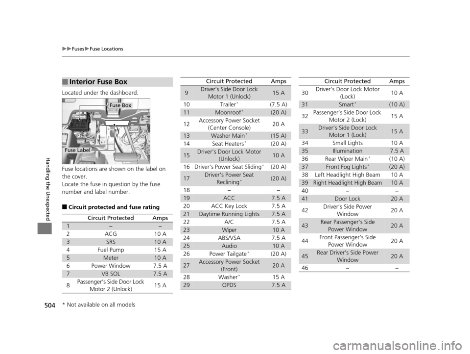
Located under the dashboard.
Fuse locations are shown on the label on
the cover.
Locate the fuse in question by the fuse
number and label number.
■Circuit protected and fuse rating
■Interior Fuse Box
Fuse Label
Fuse Box
Circuit ProtectedAmps
1−−
2ACG10 A
3SRS10 A
4Fuel Pump15 A
5Meter10 A
6Power Window7.5 A
7VB SOL7.5 A
8Passenger’s Side Door Lock
Motor 2 (Unlock)15 A
9Driver’s Side Door Lock Motor 1 (Unlock)15 A
10 Trailer
*(7.5 A)
11Moonroof*(20 A)
12 Accessory Power Socket
(Center Console) 20 A
13Washer Main*(15 A)
14 Seat Heaters*(20 A)
15Driver’s Door Lock Motor (Unlock)10 A
16 Driver's Power Seat Sliding
*(20 A)
17Driver's Power Seat Reclining*(20 A)
18 − −
19ACC7.5 A
20 ACC Key Lock 7.5 A
21Daytime Running Lights7.5 A
22 A/C 7.5 A
23Wiper10 A
24 ABS/VSA 7.5 A
25Audio10 A
26 Power Tailgate*(20 A)
27Accessory Power Socket (Front)20 A
28 Washer
*15 A
29OPDS7.5 A
Circuit ProtectedAmps
30 Driver’s Door Lock Motor
(Lock) 10 A
31Smart*(10 A)
32 Passenger’s Side Door Lock
Motor 2 (Lock) 15 A
33Driver’s Side Door Lock
Motor 1 (Lock)15 A
34 Small Lights 10 A
35Illumination7.5 A
36 Rear Wiper Main*(10 A)
37Front Fog Lights*(20 A)
38 Left Headlight High Beam 10 A
39Right Headlight High Beam10 A
40 − −
41Door Lock20 A
42 Driver’s Side Power
Window 20 A
43Rear Passenger’s Side
Power Window20 A
44 Front Passenger’s Side
Power Window 20 A
45Rear Driver’s Side Power
Window20 A
46 − −
Circuit ProtectedAmps
* Not available on all models
15 CR-V-31T0A6300.book 504 ページ 2015年2月2日 月曜日 午前10時35分
Page 506 of 533
505
uuFuses uInspecting and Changing Fuses
Handling the Unexpected
Inspecting and Changing Fuses
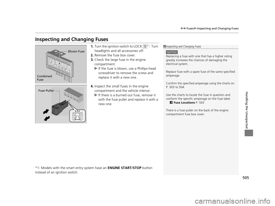
1. Turn the ignition switch to LOCK (0*1. Turn
headlights and all accessories off.
2. Remove the fuse box cover.
3. Check the large fuse in the engine
compartment.
u If the fuse is blown, use a Phillips-head
screwdriver to remove the screw and
replace it with a new one.
4. Inspect the small fu ses in the engine
compartment and the vehicle interior.
u If there is a burned out fuse, remove it
with the fuse puller and replace it with a
new one.
*1: Models with the smart entry system have an ENGINE START/STOP button
instead of an ignition switch.1 Inspecting and Changing Fuses
NOTICE
Replacing a fuse with on e that has a higher rating
greatly increases the chances of damaging the
electrical system.
Replace fuse with a spare fuse of the same specified
amperage.
Confirm the specified amperage using the charts on
P. 503 to 504.
Use the charts to locate the fuse in question and
conform the specific amperage on the fuse label. 2 Fuse Locations P. 503
There is a fuse puller on the back of the engine
compartment fuse box cover.
Combined
Fuse Blown Fuse
Fuse Puller
15 CR-V-31T0A6300.book 505 ページ 2015年2月2日 月曜日 午前10時35分
Page 507 of 533
506
Handling the Unexpected
Emergency Towing
Call a professional towing service if you need to tow your vehicle.
■Flat bed equipment
The operator loads your vehicle on the back of a truck.
This is the best way to transport your vehicle.
■Wheel lift equipment
The tow truck uses two pivoti ng arms that go under the front tires and lift them off
the ground. The rear tires remain on the ground. This is an acceptable way to
tow your vehicle.
1 Emergency Towing
NOTICE
Trying to lift or tow your vehicle by the bumpers will
cause serious damage. The bumpers are not designed
to support the vehicle's weight.
NOTICE
Improper towing such as towing behind a motor
vehicle can damage the transmission.
Never tow your vehicle with just a rope or chain.
It is very dangerous since ropes or chains may shift
from side to side or break.
All models
2WD models
15 CR-V-31T0A6300.book 506 ページ 2015年2月2日 月曜日 午前10時35分
Page 508 of 533
507
Handling the Unexpected
When You Cannot Open the Tailgate
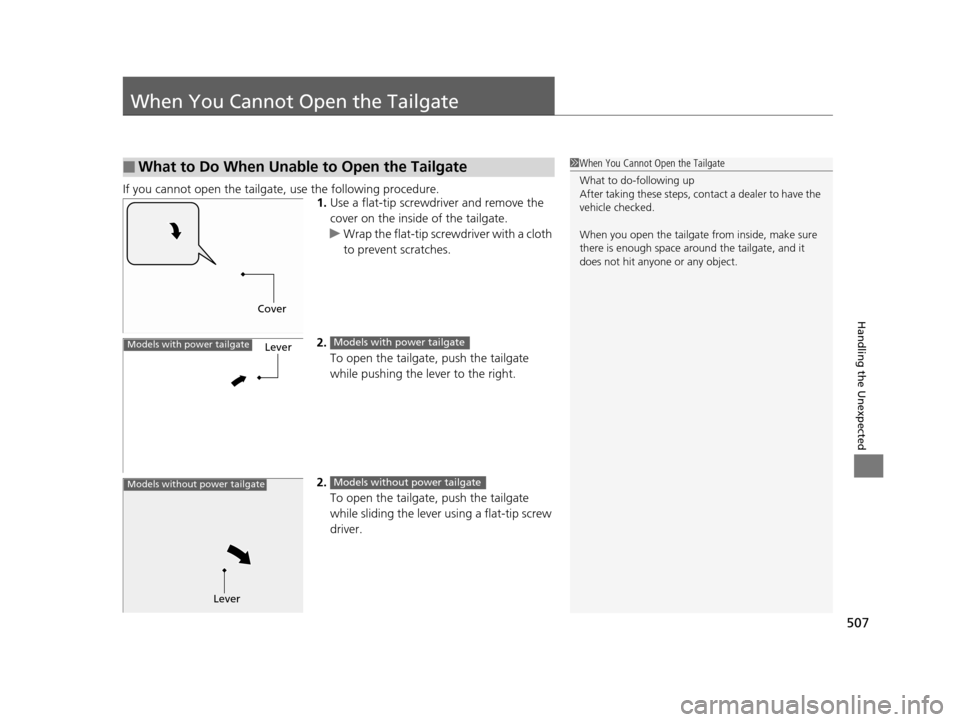
If you cannot open the tailgate, use the following procedure.1.Use a flat-tip screwdriver and remove the
cover on the inside of the tailgate.
u Wrap the flat-tip scre wdriver with a cloth
to prevent scratches.
2. To open the tailgate, push the tailgate
while pushing the lever to the right.
2. To open the tailgate, push the tailgate
while sliding the lever using a flat-tip screw
driver.
■What to Do When Unable to Open the Tailgate1When You Cannot Open the Tailgate
What to do-following up
After taking these steps, cont act a dealer to have the
vehicle checked.
When you open the tailgate from inside, make sure
there is enough space around the tailgate, and it
does not hit anyone or any object.
Cover
LeverModels with power tailgateModels with power tailgate
Lever
Models without power tailgateModels without power tailgate
15 CR-V-31T0A6300.book 507 ページ 2015年2月2日 月曜日 午前10時35分
Page 509 of 533

508
15 CR-V-31T0A6300.book 508 ページ 2015年2月2日 月曜日 午前10時35分
Page 510 of 533
509
Information
This chapter includes your vehicle's specifications, locations of identification numbers, and other
information required by regulation.
Specifications.................................... 510
Identification Numbers Vehicle Identification Number (VIN), Engine Number and Transmission
Number ......................................... 512
Devices that Emit Radio Waves ....... 513
Reporting Safety Defects ................. 514Emissions Testing
Testing of Readiness Codes.............. 515
Warranty Coverages ........................ 517
Authorized Manuals ......................... 519
Customer Service Information ......... 520
15 CR-V-31T0A6300.book 509 ページ 2015年2月2日 月曜日 午前10時35分