ignition HONDA INTEGRA 1994 4.G Owners Manual
[x] Cancel search | Manufacturer: HONDA, Model Year: 1994, Model line: INTEGRA, Model: HONDA INTEGRA 1994 4.GPages: 1413, PDF Size: 37.94 MB
Page 1085 of 1413
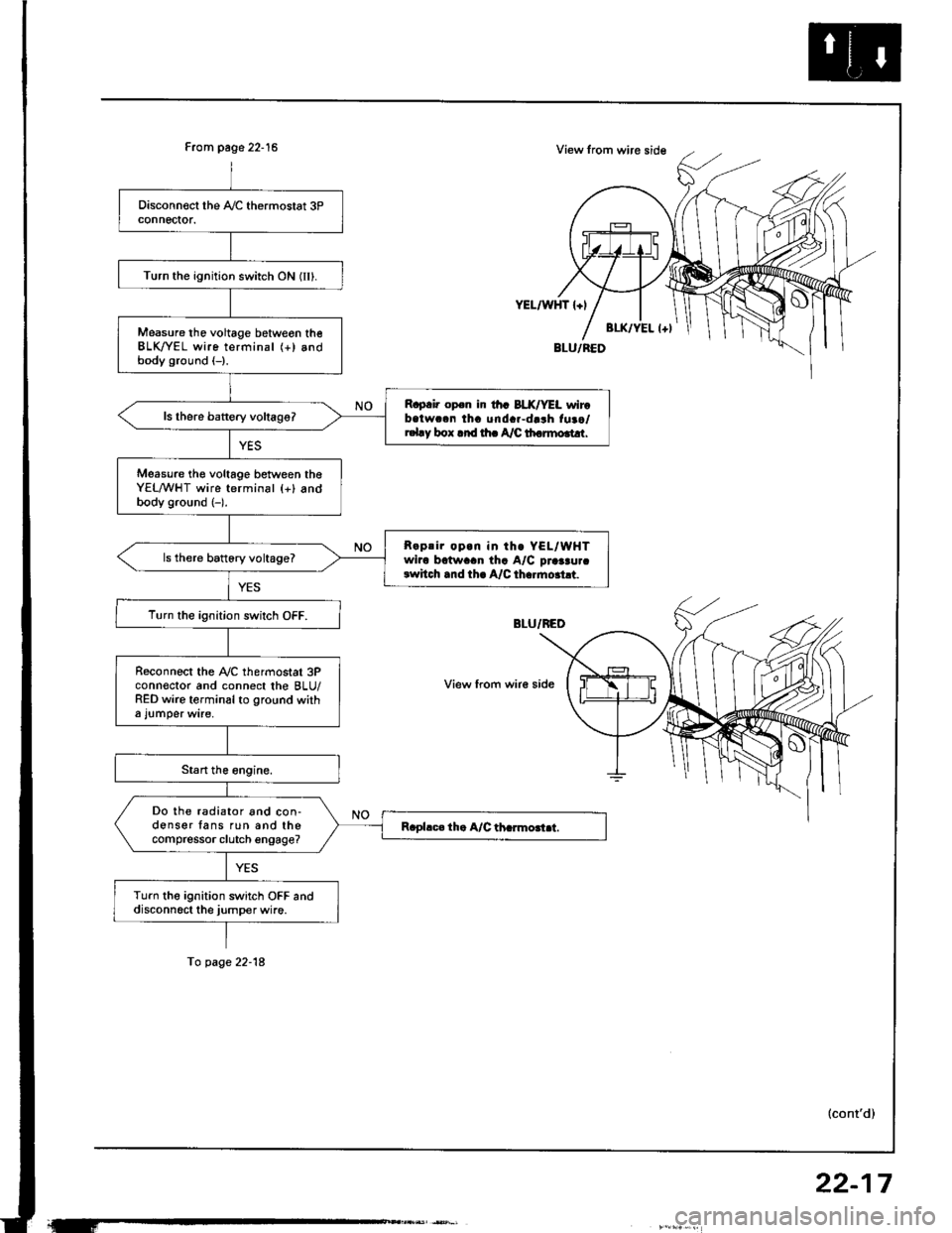
From page 22-15
Turn the ignition switch ON (IIl.
Measure tho voltage betweon theBLK/YEL wire terminal (+) andbody ground (-).
R.p.i. op.n ir th. BLX/YEL wirobatwc.n tha unda.-darh fuao/r.l.y box .rd rh. A/C th.rmo.t!r.
Measure th€ voltage between theYEL/WHT wire terminal {+} andbody ground (-).
R.prir op.n in th. YEL/WHTwiro bctwaan tha A/C praaau.crwhch .nd th. A/C th..mo.ht.
ls there battory voltage?
T!rn the ignition switch OFF.
R€connect the Ay'C thermostat 3Pconn€ctor and connect the BLU/RED wire terminal to ground witha l!mper wire,
Do the radiator and con-donser fans run and thecompressor clutch engage?
Turn the ignition switch OFF anddisconn6ct the jumper wire.
YEL/WHT l+l
View from wir€ side
To page 22-18
(cont'd)
22-17
Page 1086 of 1413
Troubleshooting
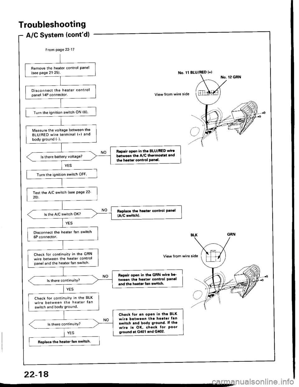
Remove the heater control Panel(see page 21 25)
Disconnect the heater controlpanel 14P connector'
Turn the ignition switch ON (lI).
Measure the voltage between the
BLU/RED wire terminal (+) and
body ground { }
Rop.i. opon in tho BLU/BED wir.
b.twoon tha A/C thermort.t lnd
the haat.r control Panal
Turn the ignition switch OFF.
ls the A/C switch OK?
Check for continuitY in the GRN
wire between the heater controlpanel and the heater fan switch
R.prir op.n in the GRN wiro be'
twoen thc hartet contlol Panaland tho h.rtor fln switch.
Check for continuity in the BLK
wire between the heater {an
switch and body ground.
Chock fol an opon in the BLK
wi.a b.tween th. hotte. hn
lwitch tnd bodY ground. ll tho
wiro it OK, chock for Poorg.ound .t G4ol .nd G402.
Replace the heater lan switch.
Frcm page 22'17
View lrom wire side
A/C System (cont'dl
No. 11 BLU/RED l+l
22-18
Page 1154 of 1413
Fuses
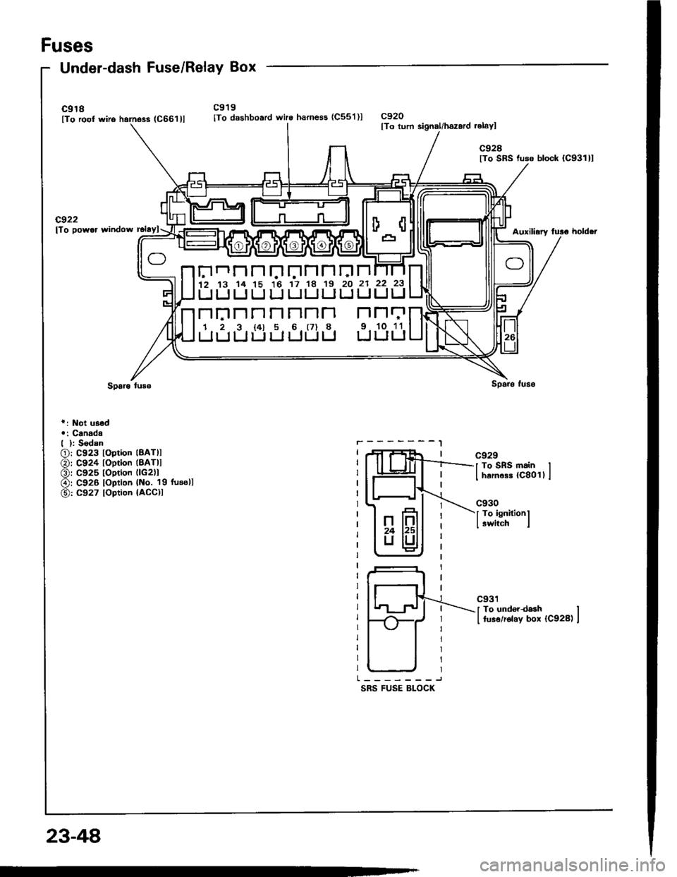
Under-dash Fuse/Relay Box
c918lTo root wiro harness (C661llc919
lTo dashboard wire harness (C55'l )lc920lTo lurn signal/hszard .elayl
c928lTo SRS luso block {C931}l
cg22lTo powor window rclaylAuxili.ry fulo holdei
r: Not usod.: Canadd| ): S6dan
O: C923 loplion lBATll
@: C924 toption (BATll
O: C925 toption llc2)1
@r C926 loption {No. 19 fusoll
@: C927 loption {ACC)I
r.-------l
SRS FUSE BLOCK
c929
J To SRS main II harnass {C8011 I
c930
I To ignitionl
I switch i
c931
I To und€rdash II fuso/rolay box {C928) I
Elnnnr.'trJnnrJn12 13 14 15 16 17 18 19 20 21
UUIJUIJULJLILIIJ
n|:]nnnnnn r''l
1 2 3 t4l 5 6 (7) 8 9.
LIIJLIULJUUU U
22 23
UIJ
N11
10 11
LILI
23-48
Page 1162 of 1413
Power Distribution
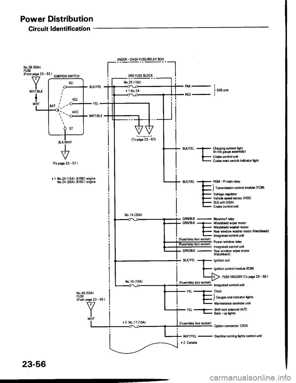
Circuit ldentification
IGNITION SWITCH
+page 23-
r 1 No.24115A): 81881 engin€No.24 l20A): Bl8C1 6ngin.
N0.40 {504)FUSE(From pago 23 - 551
UNDER - DASH FUSE/REIAY BOX
sRs FusE 81-0cK
No.25l10Al
No.14l20A)
No.l5 {1041
Chuging sY3l.m lightlln tho g6ug€ s3€mblyl
Cruis€ controlunitCdis6 msin 3whch itdicttor light
PGM - Fl mlin r6lry
) lrrmmirdon control modulo [ICM)
Vohag6 rcoulatorVehiclo sp.€d somor IVSS)E|.l) unit IUSA)Crube conttol unit
Moonrcof rclayWind.hicld wipot motorWirdlhi€ld waah6. motorR6ar window ws3hor motot {HrtchblctlInt.gGtod control unit
Power wirdow tclaY
Int6lrat€d contrcl unit- R6af window wipor motol(H3tchbtck)
571
GRNiEI(GRNAt(
GRN/8I..K
BLKffEt
-EiT"h#,H#J:r"
Shitt lock solenoU {MlEack -up lights
option conn€ctor: C924
Daytimo running lights conttol unit
YEt..--
lrcz
Ml t -'-
\'- _ ^ACC
23-56
*2 No.17 {1041bor sockstl
Page 1163 of 1413
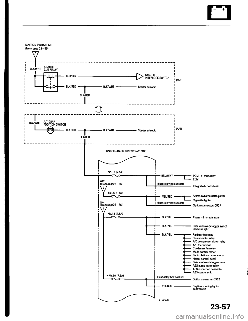
IGNITION SWTCH ISTIlFrom p.!€ 23 - 561
f7
I.---F-------lI-lSTARTFPi Bffi,!'HT 6u?'ili,iY i| -' r r l clurcr It-11iPt ;rui8rr H inl-rhicicxswrcr 1,,,,,,Itill-+{ .'.i o-F BIK/RED --.5 BLX/!\,HT - st.der sotenoid il-l I r
BLK/REO
fr
r---
uxrivn Sr$!gfr*,r.,
L€-eumoBLKMHT - Starlsr solenoki
-------J
UNDER -DASH FUSEiRELAY BOX
No.l817.5A)ELUMHT --?- PGM _ Ft msin rctay- ECM
lnt€gretod control unit
St6r6o radio/c$r€tt6 playot
Cig€rone lightor
Option connoctor: C927
Pow6r minor *tuetols
noar wandow dologgor switchindicrtor light
R6dietor fan robyElowor motor rclayfuC compr$sor clutch rsl6yA/C lhomGtstCond6ns& tan ml6yMod6 control motorRocicubtion control motorH6at€r control panolRear window deloggor relayABS pomp motor tolayABS insp€ction connoctorABS contrcl unit
Option connoctor:C925
Daytime running lightscontrolunit
(From pag623-56 )
No.23ll5AlYEURED --E
lG2lFrom p.!623- 56 ){Fus€/relay box sockotl
+ l,lo,16 {7.5A1
23-57
Page 1178 of 1413
lgnition Switch
Steering Lock Replacement
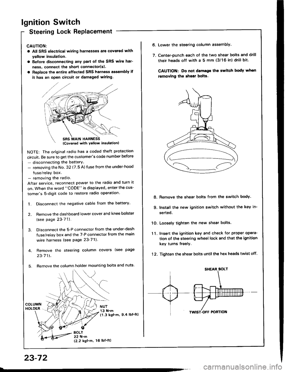
CAUTION:
a All SRS electrical wiring harnesses ale covsred with
yellow insulation.
a Belore disconnecting any parl ot the SRS wir€ hal-
ness, connecl the short connector{s).
a Replace the entire alfected SRS harness a$6mbly il
it has an open circuit or damaged wiring.
NOTE: The original radio has a coded thett protection
circuit. Be sure to get the customer's code number betore
- disconnecting the batterY.
- removing the No. 32 (7.5 A) fuse from the under-hood
fuse/relay box.- removing the radio.
After service, reconnect power to the radio and turn it
on. When the word "CODE" is displayed, enter the cus-
tomer's 5-digit code to restore radio operation.
1. Disconnect the negative cable from the battery.
2. Remove the dashboald lower cover and knee bolster
(see page 23-7'l ).
3. Disconnect the 5-P connector from the under-dash
fuse/relay box and the 7-P connector trom the main
wire harness {see page 23-71).
4. Remove the steering column covers (see page
23-711.
5. Remove the column holder mounting bolts and nuts'
BOLT22 N.m
12.2 kgl'm.
NUT13 N.m(1.3 kgf.m, 9.4 lbl'ftl
23-72
16 tbt.ftl
6. Lower the steering column sssembly.
7. Center-Dunch each oJ the two shear bolts and drill
their heads off with a 5 mm {3/1 6 in) drill bit'
CAUTION: Do not dama96 tho switch body whon
r€movlng the shoar bol$.
Remove the shear bolts from the switch body.
Install the new ignition switch without the key in-
serted.
Loosely tighten the new shear bolts.
Insert the ignition key and check for proper opera-
tion of the steering wheel lock and that th€ ignition
key turns freely.
Tighten the shear bolts untilthe hex heads twist off.
8.
q
10.
11.
12.
Page 1182 of 1413
Starting System
Startel Test
NOTE: The air temDerature must be between 59 8nd
10OoF (15 and 38oC) before testing.
Recommendsd Procodure:
a Use a staner svstem tester.
a Connect and operate the equipment in accordance
with the manutacturer's instructions.
a Test and troubleshoot as described.
Altohato Procedure:
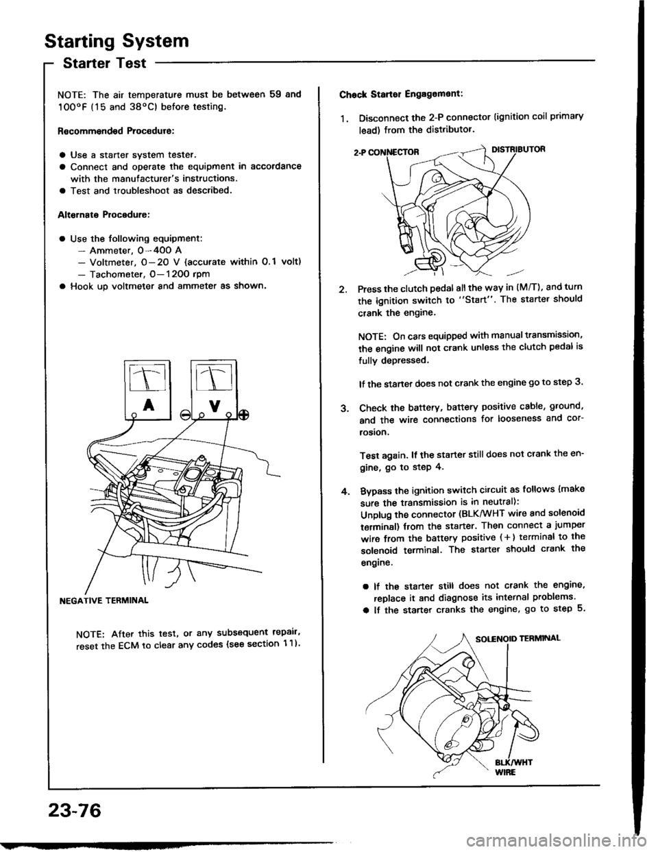
a Use the following equipment:- Ammeter. 0-4OO A- Voltmeter, O- 20 V {accurate within 0.1 volt)
- Tachometer, O- 120O rpm
a Hook up voltmeter and ammeter as shown'
NEGATIVE TERMINAL
NOTE: After this test, or any subsequent repair,
reset the ECM to clear any codes (see section 1 1)
23-76
2.
Chock Stan€r Engag6ment:
1. Disconnect the 2-P connector (ignition coil primary
lead) from the distributor.
Press the clutch pedal allthe way in (M/T), and turn
the ignition switch to "Start". The starter should
crank the engine.
NOTE: On cars equipped with manual transmission,
the engine will not crank unless the clutch pedal is
fully depressed.
lf the staner does not crank the engine go to step 3.
Check the baftery, battery positive cable, ground,
and the wire connections for looseness and cor-
rosion,
Test again. lf the starter still does not crank the en-
gine, go to step 4.
Bvpass the ignition switch citcuit as follows {make
sure the transmission is in neutral):
Unplug the connector (BLK/WHT wire and solenoid
terminsl) trom the starter. Then connect a jumper
wire from the battery positive ( + ) terminal to the
solenoid terminal. The starter should crank the
engrne.
a lf the starter still does not crank the engine,
replace it and diagnose its internal problems.
a lf the starter cranks the engine, go to step 5.
J.
4.
Page 1183 of 1413
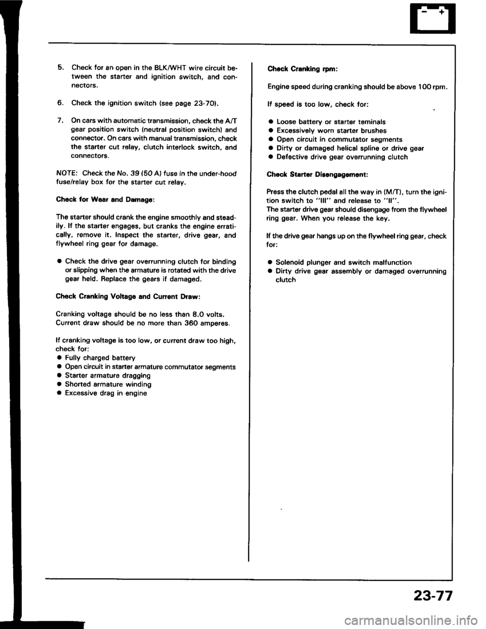
5. Check lor 8n op€n in the BLKMHT wire circuit be-
tween the staner and ignition switch, and con-
nectors.
6. Check the ignition switch (see page 23-70).
7, On cars with automatic transmission, check the A/Tgear position switch (neutral position switchl and
connector. On cars with manualtransmission, check
the staner cut relay, clutch interlock switch, and
connectors.
NOTE: Check the No. 39 (5O A) fuse in the under-hood
fuse/relay box for the starter cut relay.
Check tor Woar and Damago:
The starter should crank the engine smoothly and stead-
ily. lf th€ startsr engages, but cranks the engine errati-
cally, remove it. Inspect the starter, drive gear, and
flywheel ring gesr for damage.
a Check the drive gear overunning clutch for binding
or slipping when the armature is rotated with the drivegear held. Replace the gesrs if damaged.
Check Cranking Voltago 8nd Current Draw:
Cranking voltage should be no less than 8.O volts.
Current draw should be no more than 360 amperes.
lf cranking voltag€ is too low, or current draw too high,
check for:
a Fully charged battery
a Open circuit in starter armature commutatot segments
a Starter armature dragging
a Shoned armature winding
a Excessive drag in engine
Chack Cranking rpm:
Engine spsod during cranking should be above 1O0 rpm.
lf spe6d is too low, ch€ck for:
a Loose battsry or starter teminals
a Excessively worn starter brushes
a Open circuit in commutator segments
a Dirty or damaged helical spline or drive gear
a Defective drive gear overrunning clutch
Chock StErtor Disongagomoni:
Press the clutch pedal allth€ way in (M/T), turn the ioni-
tion switch to "lll" and rolease to "11".
The starter drive gear should disengage from the tlywheel
ring gear. When you rolease the key.
lf the drive gear hangs up on th€ flywheel ring gear, check
for:
a Solenoid plunger and switch malfunction
a Dirty drive gear assembly or damaged overrunning
clutch
23-77
Page 1193 of 1413
lgnition System
Gomponent Location Index
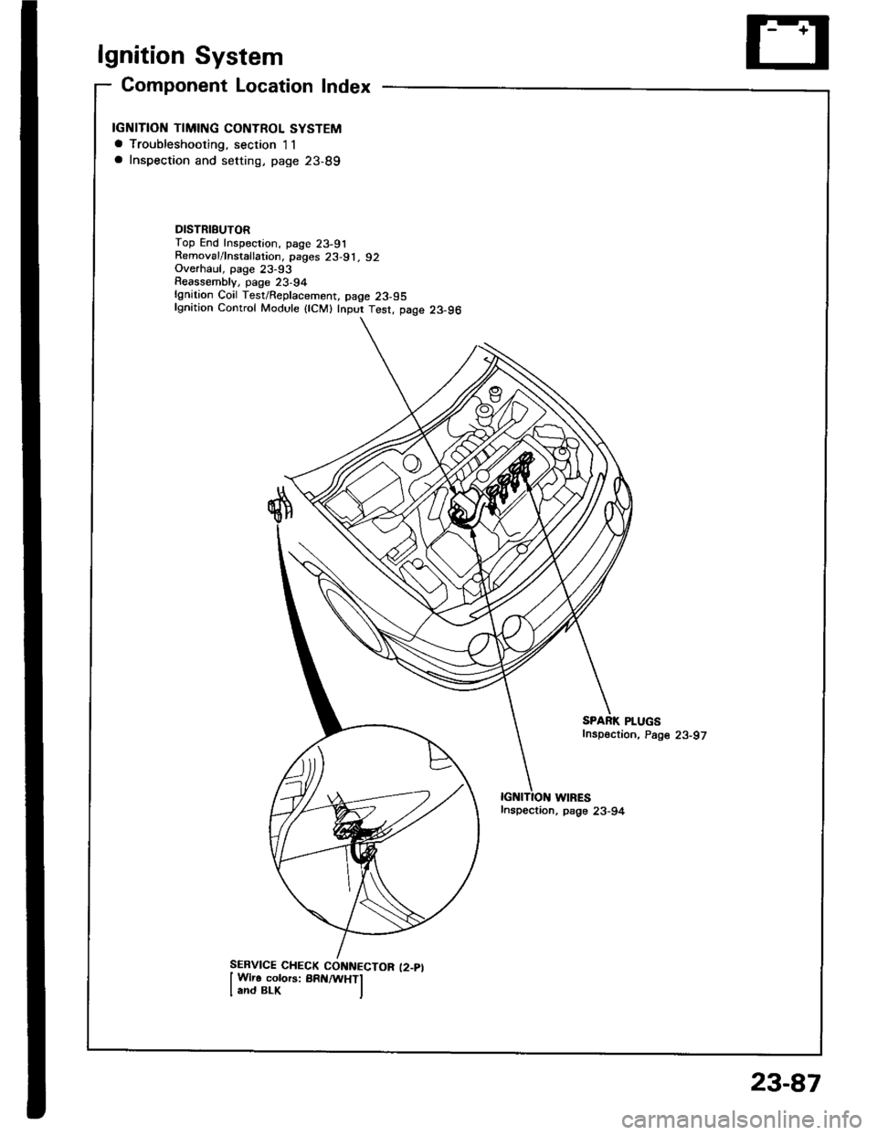
IGNITION TIMING CONTROL SYSTEMa Troubleshooting, section I1a Inspection and setting, page 23-89
DISTRIBUTORTop End Inspection, page 23-91Removal/lnstallation, pages 23-91, 92Overhaul, page 23-93Reassemblv, page 23,94lgnition Coil Test/Replacement, page 23-95lgnition Control Module {lCM} Inpur Test, page 23-96
WIRESInspection, psge 23-94
SPARK PLUGSfnspection, Page 23-97
23-87
Page 1195 of 1413
lgnition Timing Inspection and Setting
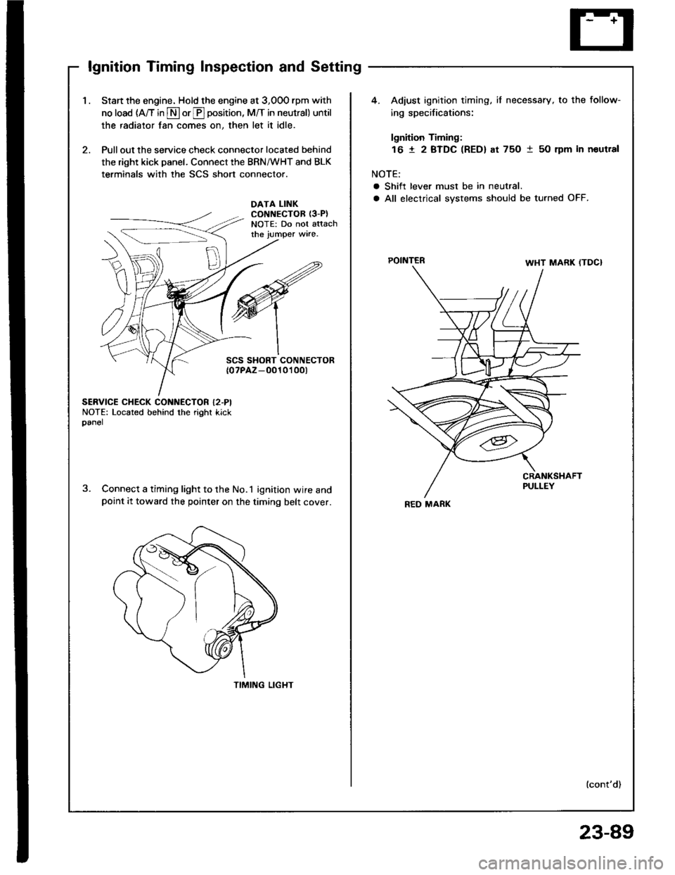
1.Start the engine. Hold the engine at 3,00O rpm with
no load (A/T in S or E position, M/T in neutral) until
the radiator fan comes on, then let it idle.
Pull out the service check connector located behind
the right kick panel. Connect the BRN/WHT and BLK
terminals with the SCS short connector.
4. Adiust ignition timing, if necessary, to the follow-
ing specifications:
lgnition Timing:
16 t 2 BTDC (RED) at 75O 1 50 rpm in noutral
NOTE:
a Shift lever must be in neutral.
a All electrical systems should be turned OFF.DATA LINKCONNECTOR {3-P}NOTE: Do not attachthe jumper wire.
POINTER
SCS SHORT CONNECTOR{0?PAZ-O010't 00t
SERVICE CHECK CONNECTOR I2.PINOTE: Located behind the right kickoanel
Connect a timing light to the No.1 ignition wire andpoint it toward the pointer on the timing belt cover.
TIMING LIGHT
lcont'd)
REO MARK
23-89