ignition HONDA INTEGRA 1994 4.G Manual PDF
[x] Cancel search | Manufacturer: HONDA, Model Year: 1994, Model line: INTEGRA, Model: HONDA INTEGRA 1994 4.GPages: 1413, PDF Size: 37.94 MB
Page 470 of 1413
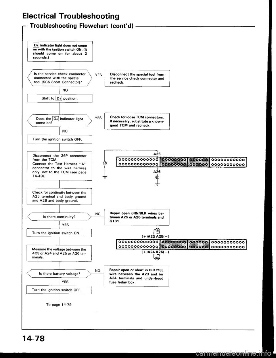
Electrical Troubleshooting
Troubleshooting Flowchaft (cont'dl
Does the @ indicatorcome on?
ls there baftery voltage?
YES
lighr
I A25
| | o ooooo o oo o ooo r:sjc.o.sl'1*st,li*os.s.4tcl ooo oo oooooo I
I I o o o o o o o o o o o o q lifrif.S..n${5git:li$gg-:aiiigitll o o o o o o o o o o o I|--.-T..-I a26
+d
+
I + )A23 A25l - l
(+ tA24 426(- |t\@
Lq4 indicator light do6s not comeon with the ignition switch ON. (ltshould come on Ior about 2seconds.l
ls the service check connectorconnected with the specialtool ISCS Short Connectod?
Diaconnect tho spocial tool fromth6 sgrvice check connoctor andrecheck.
Check {or loos6 TCM connoctors.lf necessaw, substitute a known-good TCM and recheck.
Turn the ignition switch OFF.
Disconnect the 26P connectorfrom the TCM.Connect the Test Harness "A"
conneclor to the wile harnessonly, not to the TCM (see page14-49).
Check for continuity between theA25 terminal and body groundand A26 and body ground.
R€pair open BRN/BLK wires be-twe6n A25 or A26 torminals andG 101.
Turn the ignition switch ON.
Measure the voltage between theA23 or A24 and A25 or A26 termrnals-
Repaii open or short in BLK/YELwire between tho A23 and /ot424 terminals and underhoodtuse /relav box.
Turn the ignition switch OFF.
To page 14-79
14-78
Page 471 of 1413
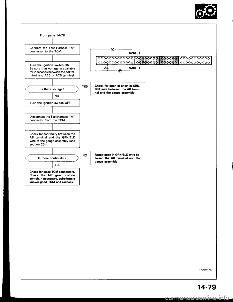
Connect the Test Harness "A"
connector to the TCM.
Turn the ignition switch ON.8e sure that voltage is availablefor 2 seconds between thg A8 tor-minal and A25 or A26 terminal.
Chrck for opon or rhort in GR /8LK wirc bctw.on th. A8 termi-nal and tha gauOa arrambly.
Turn the ignition switch OFF.
Disconnect the Test Harness "A"
connector from the TCM.
Check for continuity between theA8 terminal and the GRN/BLKwire at tho gaugo assgmbly (see
section 23).
B.p.ir op.n in GRI{/BLK wi.. bo-lwaen the A8 terminal and th.gauga 6aaombly.
Ch€ck for loor6 TCM conn6ctor3.Check the A/T goa. polition
awitch. ll noc€$ary, subrtitutg aknown-good TCM .nd rochock.
ooooooooooo
ooooooooooo
oooooooooooo
oooooooooooo
a26t - |
A8(+)
(cont'd)
14-79
Page 561 of 1413
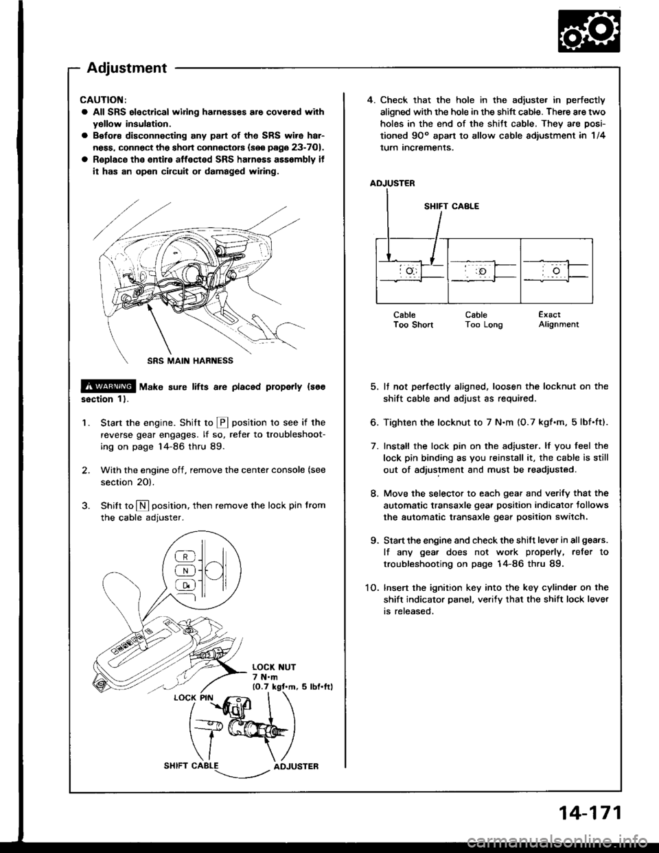
4. Check that the hole in the adiuste. in perfectly
aligned with the hole in the shift cable. There are two
holes in the end of the shitt cable, They are posi-
tioned 9Oo apart to allow cable adiustment in 1/4
lurn Incremenls.
ADJUSTER
CableI oo snonCableToo LongExactAlignment
5. It not perfectly aligned, loosen the locknut on the
shift cable and adjust as required.
6. Tighten the locknut to 7 N.m (O.7 kgf.m, 5lbf.ft).
7. Install the lock pin on the adiuster. lf you feel the
lock pin binding as you reinstall it, the cable is still
out of adjustment and must be readjusted.
8. Move the selector to each gear and verify that the
automatic transaxle gear position indicator tollows
the automatic transaxle gear position switch.
9. Start the engine and check the shift lever in all gea.s.
lf any gea. does not work properly, refer to
troubleshooting on page 14-86 thru 89.
1O. lnsert the ignition key into the key cylinder on the
shift indicator panel, ve.ify that the shift lock lever
is released,
CAUTION:
a All SRS electrical widng harn€sses are covar€d with
yollow insulation.
a Before disconnecting any part of ths SRS wire har-
ness, connect the shon connectors (see page 23-701.
a R€place the entire affected SRS halnass asssmbly it
it has an op€n circuit or damaged wiring.
@ tu"t" sure lifts a.e placed properly ls66
ssction 1).
Start the engine. Stritt to @ position to see if the
reverse gear engages. lf so, refer to troubleshoot-
ing on page 14-86 thru 89.
Wilh the engine off, remove the center console {see
section 20).
Shilt to N position. then remove the lock pin from
the cable adjuster.
'1.
/
''fidlfr
I
t+@
\/ \
CABLE-.'.-_--l../ADJUSTER
]H
@
@
@
Adjustment
14-171
Page 610 of 1413
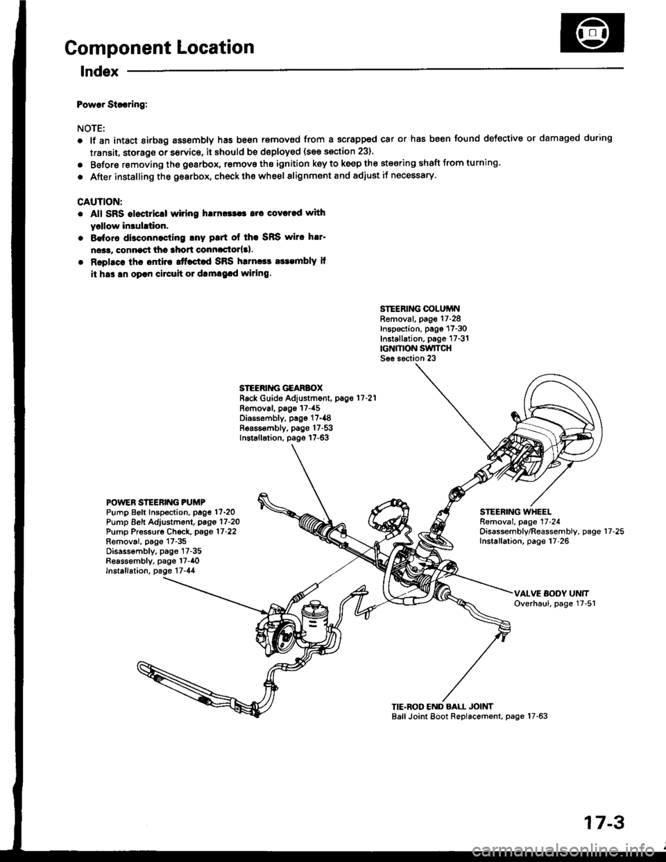
Component Location
lndex
Powar Siooring:
NOTE:
a
a
It an intact airbag ass€mbly has been r€moved from a scrapped car or has been found defective or damaged during
transit. storage or service, it should be doploy€d (see section 23).
Before removing tho gearbox, remove ths ignition key to keep the steering shaft Jrom turning.
After installing the gearbox, check ths whe€l alignment and adiust if necessary.
CAUTION:
. All SRS aloctricll wiring h!m!|$a rrc covcred with
yrllow in3uhtion.
. 8€for€ disconnocling lny ptrt ol thc SRS wiro h!r'
ne*r, connect thc lhort conncctor{3l.
. Rcplsce lhc ontira ttfact d SRS harnccc a$embly il
it hs3 !n oprn circuh 01 dtm!9.d wiring.
SIEERING COLUiINRemoval, page 17-28Inspection, pago 17-30Installation, p6ge 17-31rcNMON SwlTCHSee s6ction 23
STEERII{G GEARBOXRack Guide Adjustment, pag.11-21
Removal, pags 17-45Diossombly, page 17-{8Bea65€mbly, page 17-53Installation, page 17-63
POWEN STEERING PUMPPump Beft Inspoction. page 17-2OPump Eeft Adjustm6nl, pago 17-2OPump Pressurg Ch€ck, page 17-22Removai, p6go 17-35Disassembly, p3gs 17-35Reassombly, psge l7-40lnstallation, page 17-44
STEERING WHEELRemoval. page 17-24Oisassembly/Reassembly, pageInstallation, page 17-2617-25
TIE'ROD END BALL JOINTBall Joint Eoot Replacement, page 17-63
17-3
Page 634 of 1413
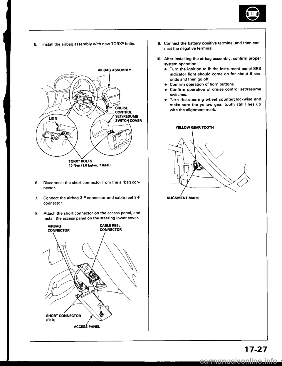
5. Install the airbag assembly with new TORXo bolts.
TORXO BOLTS10 N.m {1.0 kgf'm.7 lbf ftl
Disconnect the short connector trom the airbag con-
nector.
Connect the airbag 3-P connector and cable reel 3-P
connector.
Attach the short connector on the access panel. and
install the access panel on the steering lower cover.
CABLE REEI-CONNECTOR
7.
YELLOW GEAR TOOTH
ALIGNMENT MARK
10.
Connect the battery positive terminal and th€n con-
nect the nsgative terminal.
After installing the sirbag assembly, confirm proper
system opera(on:
. Turn the ignition to ll: the instrum€nt pan6l SRS
indicator light should come on for about 6 sec-
onds and then go off,
. Confirm operation of horn buttons.
. Confirm oDeration of cruise control sevresume
switches.
a Turn the steering wheel countetclockwise and
make su.e the yellow gear tooth still lines up
with the alignment mark.
17-27
Page 636 of 1413
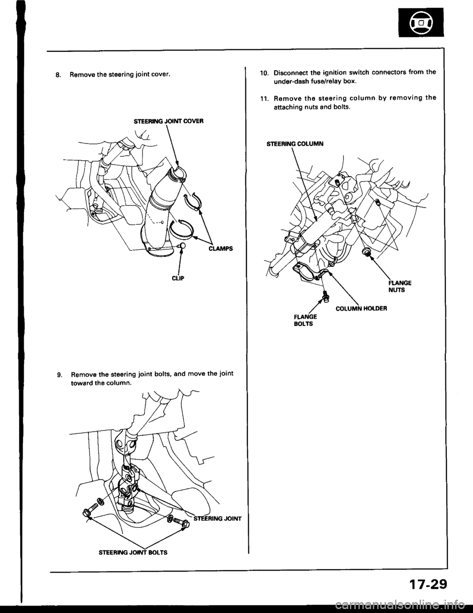
8. Remov€ the stesring ioint cover.
Remove tho steering joint bolts, and move the ioint
toward ths column.
JOIMT OOVER
STEERING COLUMN
BOITS
10.
'l1.
Disconnoct the ignition switch connectors from th6
undor-dash fuse/relav box.
Remove tho steering column by removing the
attaching nuts 8nd bolts.
17-29
Page 640 of 1413
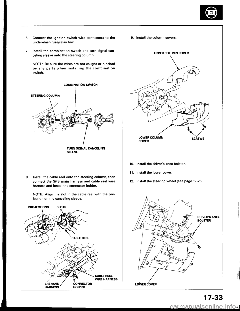
7.
Connect the ignition switch wire connectors to the
under-dash fuse/relav box.
Install the combination switch and turn signal can-
celing sleeve onto the steering column.
NOTE: Be sure the wires are not caught or pinched
by any parts when installing the combination
switch.
TURN SIGNAL CANCELINGSLEEVE
Install the cable reel onto the steering column, then
connect the SRS main harness and cable reel wiro
harness and install the connector holder.
NOTE: Align the slot in the cable reel with the pro-
jection on the canceling sleeve.
coMatNATroN swncH
UPPER COLUMN COVER
9. Installthe column covers.
scREws
lnstall the driver's knee bolster.
lnstall the lower cover.
Installthe steering wheel {see page '17-26).
10.
11.
't2.
17-33
Page 652 of 1413
Steering Gearbox
Removal
NOTE: Using solvent and a brush, wash any oil and dirt
off the valve body unit, its lines, and the end if the gear-
box. Blow dry with compressed air.
1. Drain the power steering fluid as described on page
17 -21.
2. Rsise the front of car, and support on safety stands
in the propsr locations (see section 1).
3. Remove the front wheels.
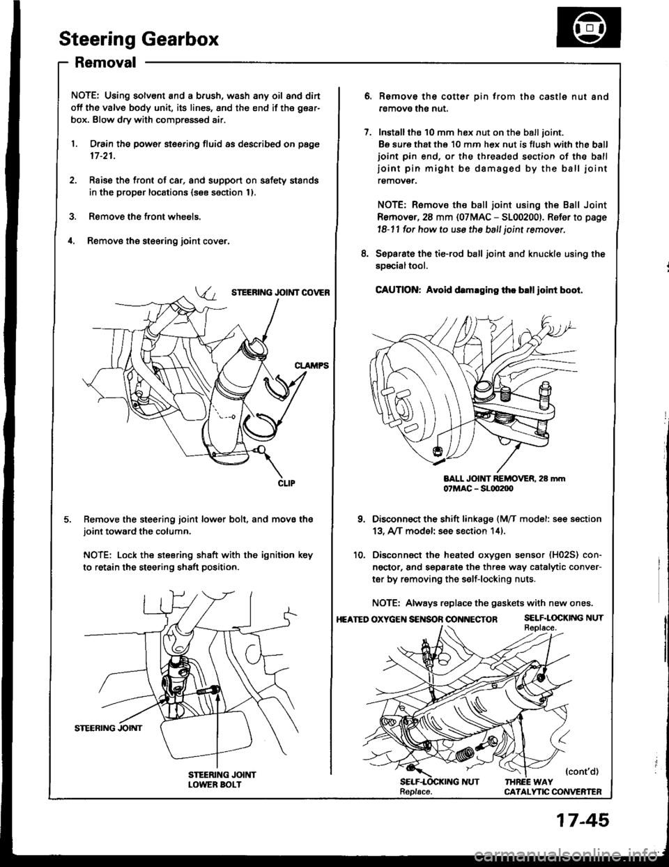
il. Removs the st€ering joint cove.,
SIEERING JOIi{T COVEB
Remove the steering joint lower bolt, and move thejoint toward the column.
NOTE: Lock the steering shaft with the ignition key
to retain the steering shaft position.
Remove the cotter pin trom the castle nut and
removo the nut.
Installthe 10 mm hex nut on the balljoint.
Be sure that ths 10 mm hex nut is flush with the ball
ioint pin end, or the threaded section of the ball
ioint pin might be damaged by the ball iointremover.
NOTE: Remove the ball joint using the Ball Joint
Remover, 28 mm {07MAC - 5100200}. Refer to page
l8-11 fot how to use the ball joint rcmover,
Separat€ the tie-rod ball joint and knuckle using the
soscialtool.
CAUTION: Avold d.maging th. blllloint boot.
BALL JOlt{T REMOVER. 28 mm07MAC - SLqt2|X)
Disconnect the shift linkage {MfI model: see section
13, A/[ model see section 14).
Disconnect the heated oxygen sensor (H02S) con-
ngctor, and separate the three way catalytic conver-
ter by removing the s€lf-locking nuts.
NOTE: Always replace the gaskets with new ones.
OXycEt{S€NSOnOONNECTOR SELF.LOCKINGNUT
{cont'd)IHREE WAYCA?ALYTIC CONVERTEN
8.
10.
HEATED
Replacs.
17-45
Page 1046 of 1413
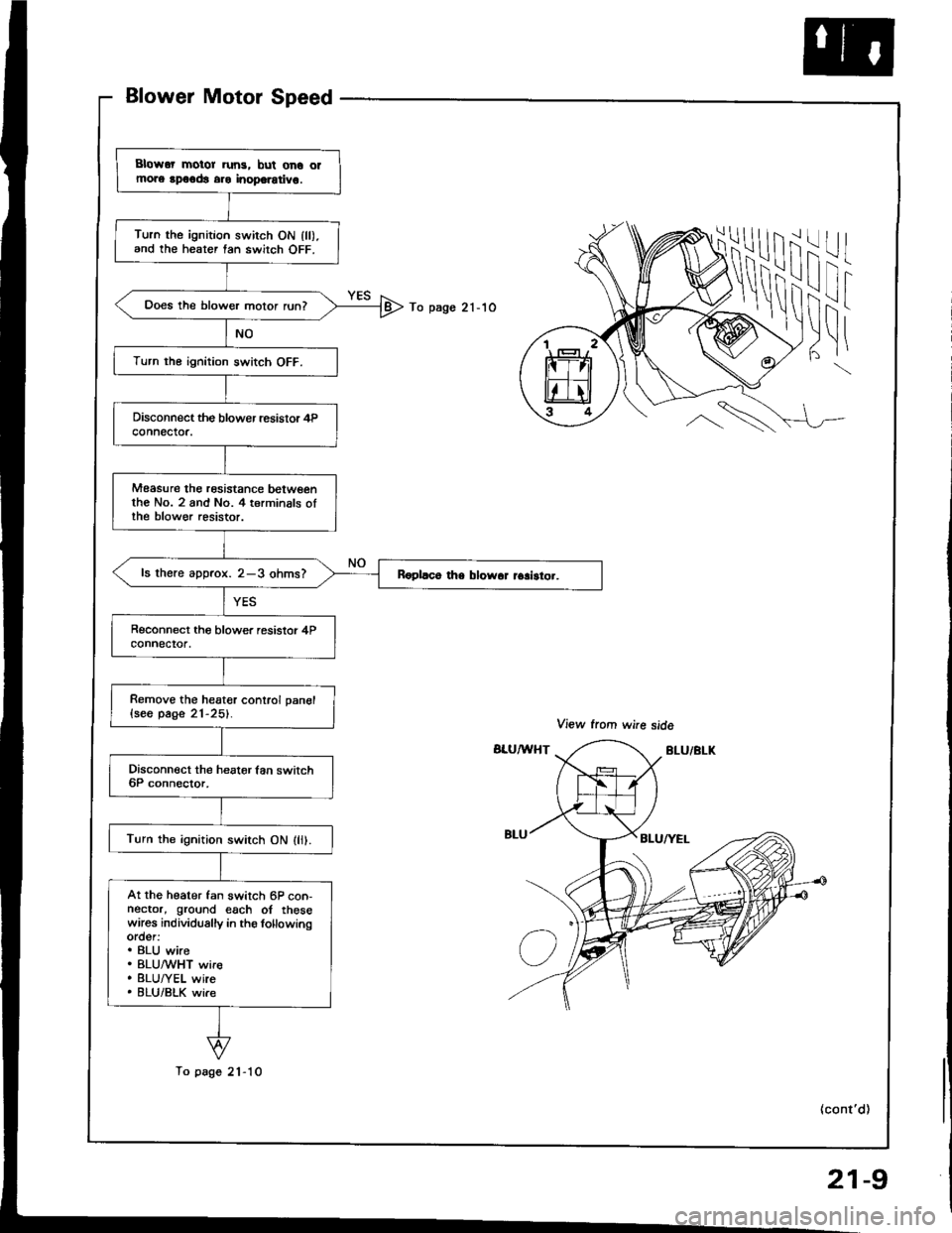
Blower Motor Speed
iii
I!i
-l
I
To pago 21-1O
l|t|
\
\
Blowor motor run3, bul ono olmors rpoodt aro inoporotivo.
Turn the ignition swirch ON lll).and the heater tan switch OFF.
Does the blower motor run?
Turn the ignition switch OFF.
Measure the rosistance betwoenthe No. 2 and No. 4 terminals oIthe blow€r resistor.
ls there aDorox. 2-3 ohms?
Remove the heater conlrol pan€l{seo page 21-25}.
Turn the ignition switch ON (li).
At the heater fan switch 6P con-nector, ground each of thesewares individually in ths lollowingorder:. BLU wire. BLUMHT wir€. BLU/YEL wire. 8LU/BLK wi.e
To page 21-10
(cont'd)
21-9
Page 1047 of 1413
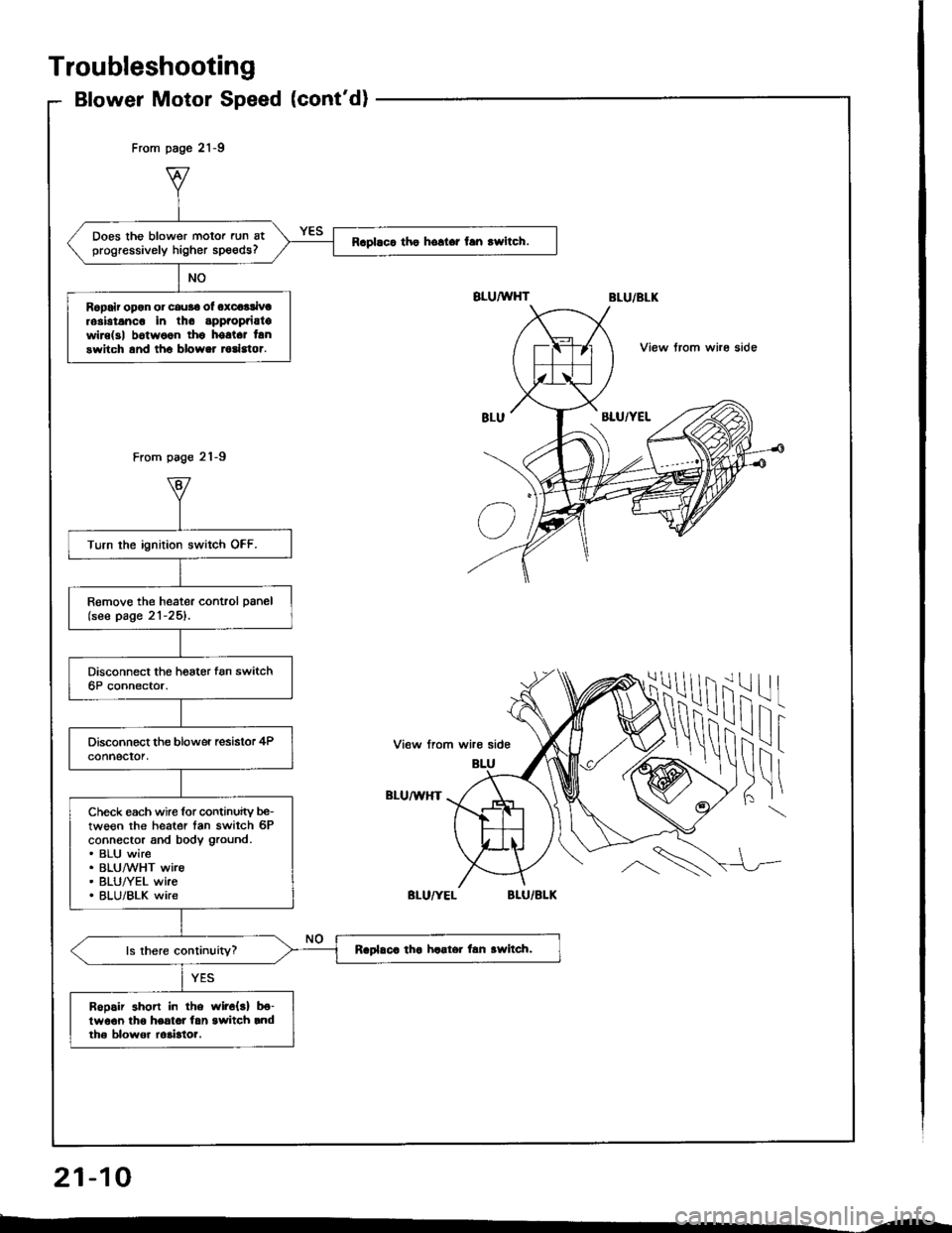
Does the blower motor run atprogressively higher speeds?Raplaca tho hollar fan rwitch.
Ropair opon or cau36 ol oxcoalivtrosbtanco in tho appaopaiatowire(3| b6twoon thg hostct lanswitch and tho blower todstor.
Turn the ignition switch OFF.
Remove the heater control panel(see page 21-25).
Check each wire for continuity be-tween the heater tan switch 6Pconnector and body ground.. BLU wire. BLUMHT wire. BLU/YEL wke. BLU/BLK wire
Raplaca tha haater lan awltch.
Bopair shon in the wir6{s} b€-lwo€n lho heatot lan switch rndth6 blowor ro3bto?.
From page 21-9
From page 21-9
View trom whe side
ilil
!\i
-l
I
View from wire side
BLU/U,HT
Troubleshooting
Blower Motor Speed (cont'd)
21-10
--