fuse box HONDA INTEGRA 1994 4.G Workshop Manual
[x] Cancel search | Manufacturer: HONDA, Model Year: 1994, Model line: INTEGRA, Model: HONDA INTEGRA 1994 4.GPages: 1413, PDF Size: 37.94 MB
Page 1328 of 1413
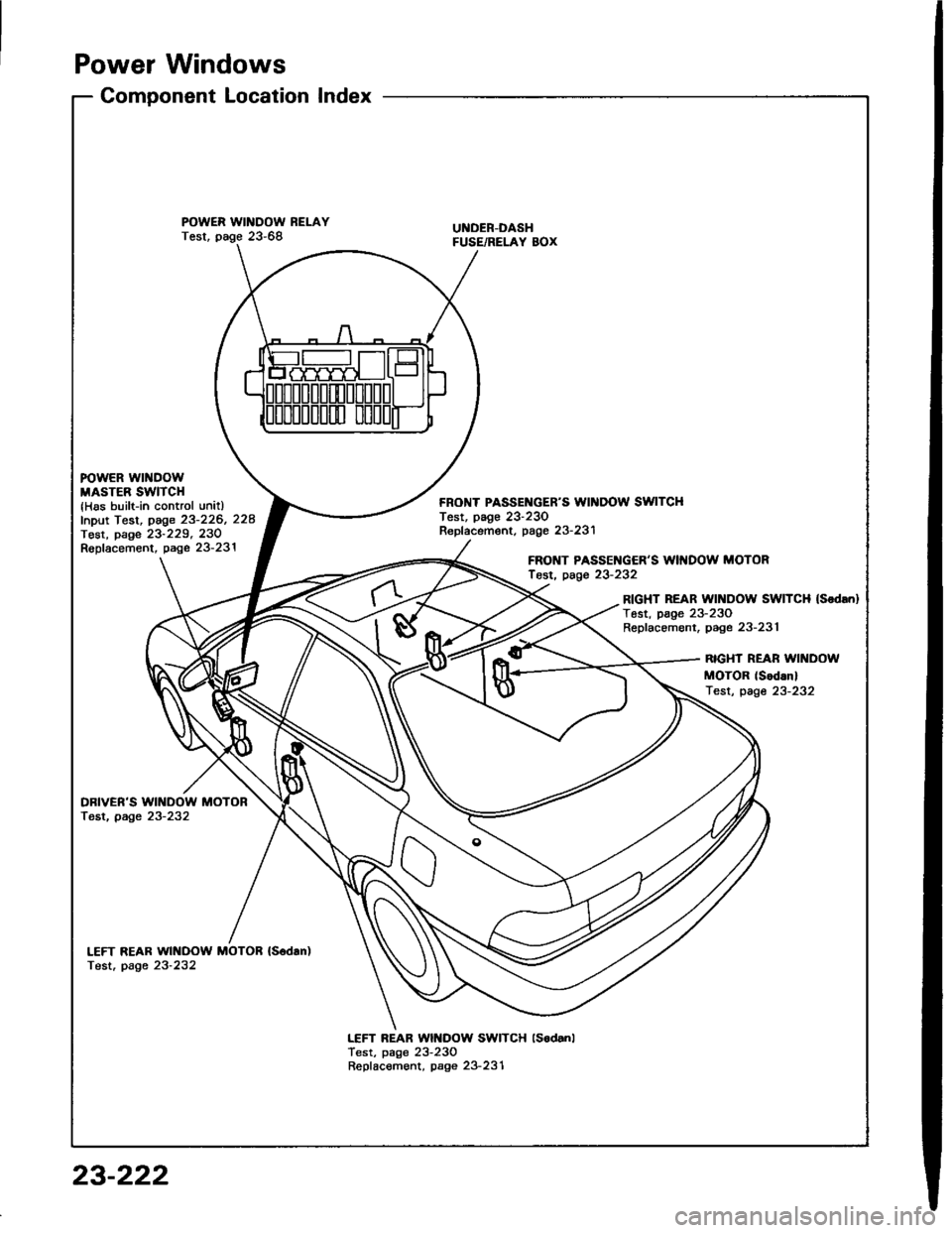
Power Windows
Component LocationIndex
POWER WINDOW RELAYTest, page 23-68UI{DER-DASHFUSE/RELAY BOX
FOWER WINDOWMASTER SWITCH{Has built-in control unitlfnput Test, page 23-226, 228Tost, page 23-229, 23ORopfacement, page 23-231
FRONT PASSEI{GER'S WII{DOW SWITCHTest, page 23-230Repf acement. page 23- 231
FRONT PASSENGER'S WII{DOW MOTORfosr, page 23-232
RIGHT REAR Wll{DOW SWITCH (Sodrn}
Tost, page 23-230Replacement, page 23-231
RIGHT REAR WII{DOW
MOTOR (Sod.nl
Test, page 23-232
DBIVER'S WINDOW MOTORTest, page 23-232
LEFT REAR WINDOW MOTOB {S6dan)Test. page 23-232
LEFT REAR Wlt{DOW SWITCH lsodanlTest, page 23-230Repfacement, page 23-231
23-222
Page 1329 of 1413
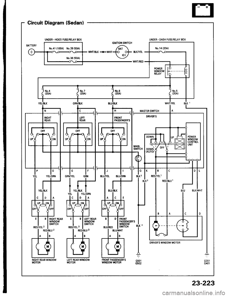
UNOER-HOOO FUSE/RELAY 8OX
Circuit Diagram (Sedanl
G20rG401
UNDER_ DASH FUSE/RELAY BOX
LEFT REARWINDOWMOTORRIGHT REAN WINOOWMOTORFROI{T PASSENGER'SwrNoow i,roToRG501G502
DRiVER'S WINOOW MOTOR
23-223
Page 1330 of 1413
![HONDA INTEGRA 1994 4.G Workshop Manual Power Windows
Circuit Diagram (Hatchback)
UNDER - HOOD FUS€/REI.AY BOX
tlo.41 l100Al ilo.39 {50A)
UNOER- OASH FUSE]NEI.AY 8OX
8LX z
G50tG502
D PASSENGERSwrNDowswITcH
PASSENGENSwtN00w M0T0nG401
23- HONDA INTEGRA 1994 4.G Workshop Manual Power Windows
Circuit Diagram (Hatchback)
UNDER - HOOD FUS€/REI.AY BOX
tlo.41 l100Al ilo.39 {50A)
UNOER- OASH FUSE]NEI.AY 8OX
8LX z
G50tG502
D PASSENGERSwrNDowswITcH
PASSENGENSwtN00w M0T0nG401
23-](/img/13/6067/w960_6067-1329.png)
Power Windows
Circuit Diagram (Hatchback)
UNDER - HOOD FUS€/REI.AY BOX
tlo.41 l100Al ilo.39 {50A)
UNOER- OASH FUSE]NEI.AY 8OX
8LX z
G50tG502
D PASSENGER'SwrNDowswITcH
PASSENGEN'SwtN00w M0T0nG401
23-224
Page 1333 of 1413

Test conditionT€st: Desirod rosultPossibl€ cause if result is not obtainad
BLK2
ano
BLK3
Under all conditionsCheck for continuity to ground:
There should be continuitv,
. Poor ground {c501, G502). An open in the wire
WHT/YELlgnition switch ON (lllCheck for voltage to ground:
The.e should be battery voltage.
Blown No. 14 (20 Al fuse in the
under-dash fuse/relay box
Bfown No. 5, 8, 7 ot 4 l2O Al fuse
in the under-dash fuse/relay box
Faulty power window relay
An open in the wire
BLU/BLK
GRN/BLK
YEL/BLK
RED/BLU1
ano
REDATELl
Connect the WHT/YEL
and RED/YEL1 terminals,
and the RED/BLU1 and
BLK3 terminals with jum-
per wires, then turn the
ignition switch ON (lll.
Check the driver's window
motor:
It should run (the window
moves down).
. Faulty drivea's window motor. An open in the wire
4
BLU/YEL
and
BLU/GRN
Connect the BLU/BLK
and BLU/GRN terminals,
and the BLU/YEL and
BLK, terminals with jum-
per wires, then turn the
ignition switch ON (ll).
Check the tront passenger's
window motor:
It should run {the window
moves down).
. Faulty front passenger's window
motOa. An open in the wire
5
GRN/YEL
ano
GRN
Connect the GRN/BLK
and GRN terminals, and
the GRN/YEL and 8LK,
terminals with iumperwires, then turn the igni-
tion switch ON (ll).
Check the left fear window
motor:
It should run (the window
moves down).
Faulty left rear window motof
Faulty lett rear window switch
An oDen in the wire
6
YEL/GRN
and
YEL
Connect the YEL/BLK
and YEL/GRN terminals,
and the YEL and BLK,
terminals with iumper
wires, then turn the igni-
tion switch ON (ll).
Check the right rear window
motor:
It should run (the window
moves down).
Faulty .ight rea. window motor
Faulty right rear window switch
An open in the wire
7
BLU
ano
BLK/VVHT
Connect the WHT/YEL
and RED/YEL1 terminals.
and the REo/BLU1 and
BLK3 terminals with jum-
per wires. then turn theignition switch ON (ll).
Conned an analog ohmmeter tote.minals BLU and BLK/wHT:
The meter needle should move
back and lorth alternatelv asthe driver's window motor runs.
Faulty pulser
Faulty driver's window motor
An open in the wire
23-227
Page 1334 of 1413
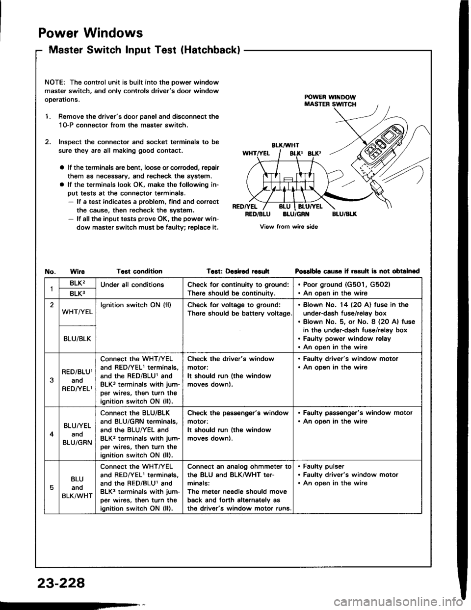
Power
Master
Windows
Switch lnput Test(Hatchback)
NOTE: The control unit is built into the power window
master switch, and onlv controls driver's door window
operations,
1. Remove the driver's door panal and disconnect the
1O-P connectol from the master switch.
2. lnsDect the connector and socket terminals to be
sure they are all making good contact.
a lf the terminsls arc bent, loose or corroded, rspair
them as necessary, and recheck the system.
a lf the terminals look OK, make the following in-
put tests at the connector terminals.- lf a test indicates a problem, find and correct
the cause, then recheck the systsm.- lf all the input tests prove OK, the powsr win-
dow master switch must be faulty; replace it.
RED/YEL
RED/BLUBLU/GR'{BLU/BLK
View from wirs sido
WiroTost conditionTost: Dashod r€suhPGslblo cluso if rosuh ir not obtalnad
1BLK'Under all conditionsCh€ck for continuity to ground:
There should be continuity.
Poor ground (G501, G5O2)
An oDen in the wire8LK3
WHT/YELlgnition switch ON {ll)Ch6ck for voltags to ground:
Th€re should be battery voltage.
Blown No. 14 l2O Al fuse in the
under-dash fuso/relay box
Blown No. 5, or No. 8 (2O A) tuse
in the under-dash luse/relay box
Faulty power window relay
An oDen in the wire
BLU/BLK
RED/BLU1
ano
RED/YELI
Connect the WHT/YEL
and REDfYELI terminals,
and the RED/BLU1 and
BLK3 terminals with jum-
per wires, then turn the
ignition switch ON {ll).
Check the driver's window
motor:
It should run (the window
moves down).
. Faulty driver's window motor. An ooen in th€ wire
4
BLU/YEL
and
BLU/GRN
Connect the BLU/BLK
and BLU/GRN terminals,
and the BLUTYEL and
BLK2 terminals with jum-
per wires, then turn the
ignition switch ON {ll).
Check ths passengor's window
motor:
It should run (the window
moves down).
. Faulty pass€nger's window motor. An oD€n in the wire
5
BLU
anq
BLKMHT
connect the WHTTYEL
and BEDrYELI terminals,
and the RED/BLU1 and
BLK3 terminals with jum-
pe. wires, then turn the
ignition switch ON (ll).
Conn€ct an analog ohmmeter to
thE BLU ANd BLKMHT t€Tr
minals:
The meter needle should move
back and torth alternately as
th€ driver's window motor runs.
Faulty pulser
Faultv driver's window motor
An oDen in the wire
23-228
Page 1340 of 1413
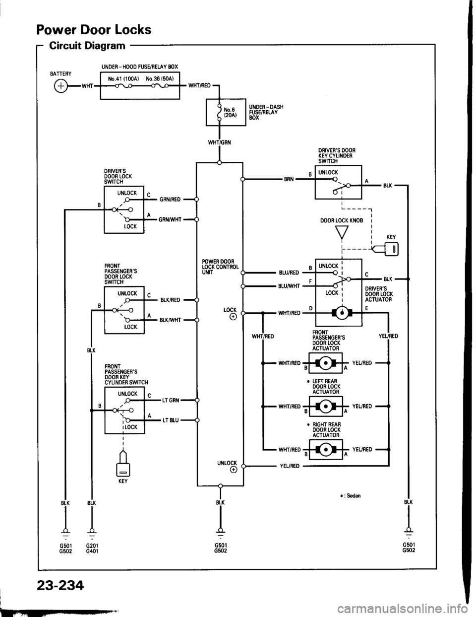
Power Door Locks
Circuit Diagram
BATTENY
@'"t
BLK
.&;
G201G401
o00R toc( KN08
VL____I
FROMTPASSENGER'SoooR t-ocKACIUATOR
@r
I uFt REAR000R LocKACTUATOR
@"
r RIGHT REAR000R LocKACTUATOR
@'
8LK
A=
G501G5o2
I
G501G5o2
UiIDER- HOOD FUSE/RELAY BOX
No.41 l100Al iJo,36l50A)
DRIVER'S OOOBKEY CYI,INDERswITcH
DRIVER'SoooR rocKswtTcH
FRONTPASSENGEN'SDOOR LOCKswncH
POWER OOORLOCK CONTROI.
8rl(
A-l
GSotG502
23-234
I
Page 1343 of 1413
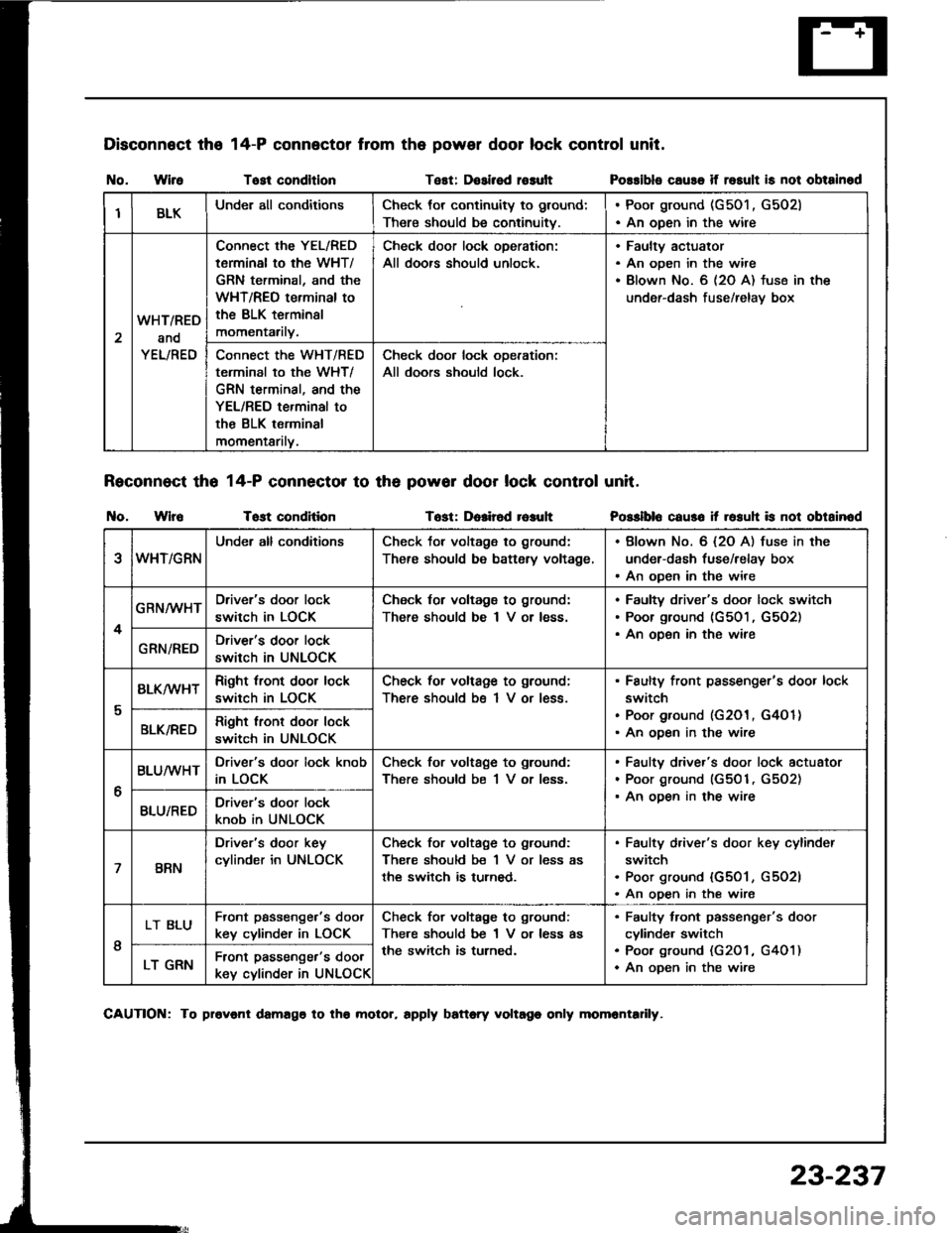
Disconnect the
I{o. WireTost condltlonTest: Dosirsd rosult
Reconnect tho 14-P connector to th6 powor door lock control unit.
t{o. WlroTost conditionTost: Dolir6d r6auh
14-P connector from the power door lock control unit.
Possibls cause if rosult is not obtainod
Posslblo caus6 it rosuh is not obtainod
IBLKUnder all conditionsCheck tor continuity to ground:
There should be continuitv.
. Poor ground (G501 , G502). An open in the wire
2
WHT/RED
and
YEL/RED
Connect the YEL/RED
tarminal to the WHT/
GRN terminal, and the
WHT/REO terminal to
the BLK terminsl
momentarily.
Check door lock oDeration:
All doors should unlock.
Faultv actuator
An open in the wire
Blown No. 6 (2O A) fuse in the
under-dash fuse/relav box
Connect the WHT/RED
terminal to the WHT/
GRN terminal, and the
YEL/RED terminal to
the BLK terminal
momentarilv.
Check door lock ooeration:
All doors should lock.
eWHT/GRN
Under all conditionsCheck tor voltage to ground:
There should be battsry voltage.
. Blown No. 6 {2O A) fuse in the
under-dash fuse/relay box. An open in the wire
4
GRN/WHTDriver's door lock
switch in LOCK
Check for voltagg to ground:
There should be I V or less.
Faultv driver's door lock switch
Poor ground (G501, G5O2)
An oDen in the wireGRN/REDDriver's door lock
switch in UNLOCK
I
BLK/wHTRight tront door lock
switch in LOCK
Check for voltage to ground;
There should bs 1 V or less.
Faulty front passenger's door lock
switch
Poor ground (G201, G4O 1)
An ooen in the wireBLK/REDRight lront door lock
switch in UNLOCK
6
BLUMHTDriver's door lock knob
in LOCK
Check for voltage to ground:
There should be 1 V or less.
Faulty driver's door lock actuator
Poor ground (G501, G5O2)
An ooen in the wireBLU/REDDriver's door lock
knob in UNLOCK
7BRN
Driver's door key
cylinder in UNLOCK
Check for voltage to ground:
There should be 1 V or less as
the switch is turned.
Faulty d,iver's door key cylinder
switch
Poor ground {G501, G5O2l
An open in the wire
I
LT BLUFront passenge.'s doot
key cylinder in LOCK
Check for voltage to ground:
There should be 1 V or less as
the switch is turned.
Faulty tront passenger's door
cylinde. switch
Poo. ground (G201 , G401)
An oDen in the wireLT GRNFront passenger's door
key cylinder in UNLOCK
CAUTION: To provonl damago to tho molor, rpply battory voltago only momrntadly.
23-237
Page 1350 of 1413
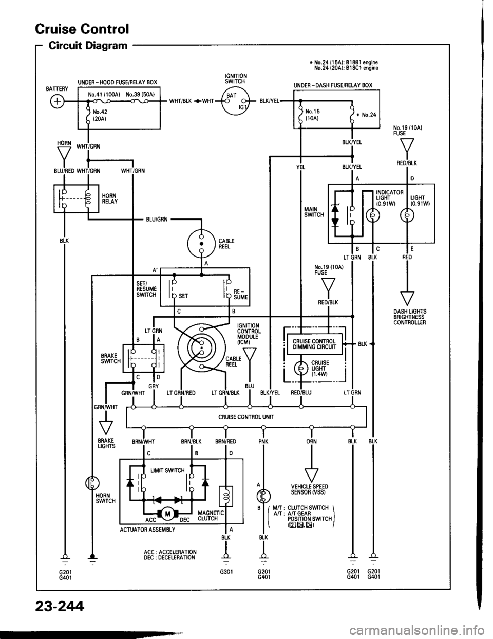
+ No.24 ll5Al: 81881 onoineNo.24 l20Al: 818C1 ensine
UNDER-DASH FUSE/RELAY BOX
HORN
Y
UNOER _HOOD FUSE/RELAY BOX
No.4l (100A) No.39l50A)
INDICATORTIGHT{0,91W}
IP
I D Suur
6yffi Bi,G#,,'.
BTK
t-
G201G401
II
I
f7
VEHICLE SPEEDSENSOR iVSS)
M/r : CLUTCH SWITCH IA/T : A/T GEAR IPOS|T|oN SWTTCH IInIEI,E) I
PNK
BI-K
T
G201G401
Cruise Gontrol
Circuit Diagram
23-244
Page 1351 of 1413
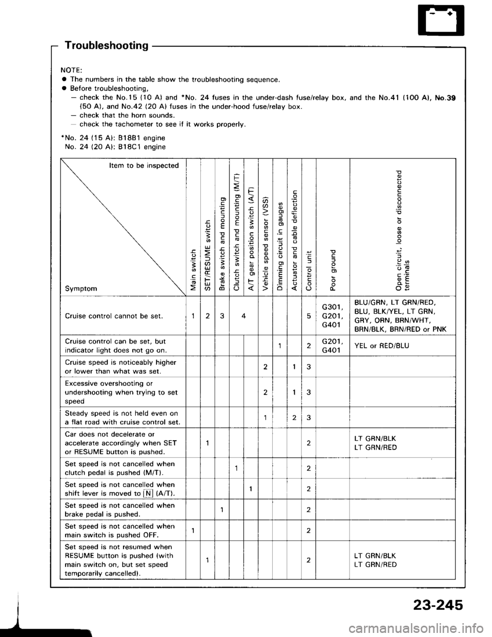
Troubleshooting
NOTE:
a The numbers in the table show the troubleshooting sequence.
a Before troubleshooting,- check the No.15 {10 A) and *No. 24 fuses in the under-dash fuse/relay box, and the No.41 (1OO A), No.39(50 A). and No.42 (20 Al fuses in the under-hood fuse/relav box.- check that the horn sounds.
check the tachometer to see if it wo.ks pfoperly.
*No. 24 {15 A): Bl8B1 engine
No. 24 {2O A}: 818C1 engine
Item to be inspected
Symptom
-c.
!I
.!o
;
U)
F
'Fcf
E
c
3
dl
F
o)
F
f
E
c
B
^
3
'.E
aa
_q
E
oi
.9:
E
.Eo
_9
l
If
L
!
.9
912'oE
og
Cruise control cannot be set.13
G301,
G201 ,
G401
BLU/GBN, LT GRN/RED.
BLU, BLK/YEL, LT GRN,
GRY, ORN. BRN/WHT,
BRN/BLK, BRN/RED or PNK
Cruise control can be set, but
indicator light does not go on.2G201,
G401YEL or RED/BLU
Cruise speed is noticeably higher
or lower than what was set.I3
Excessive overshootjng or
undershooting when trying to set
speed
2I
Steady speed is not held even on
a flat road with cruise control set.23
Car does not decelerate or
accelerate accordingly when SET
or RESUME button is pushed.
2LT GRN/BLK
LT GRN/RED
Set sDeed is not cancelled when
clutch Dedal is oushed (M/Tl.,1
Set sDeed is not cancelled when
shift lever is moved to fM tnnt.I2
Set speed is not cancelled when
brake pedal is pushed.'I2
Set speed is not cancelled when
main switch is pushed OFF.1
Set speed is not resumed when
RESUME button is pushed (with
main switch on, but set speed
temporarily cancelled).
LT GRN/BLK
LT GRN/RED
23-245
Page 1353 of 1413
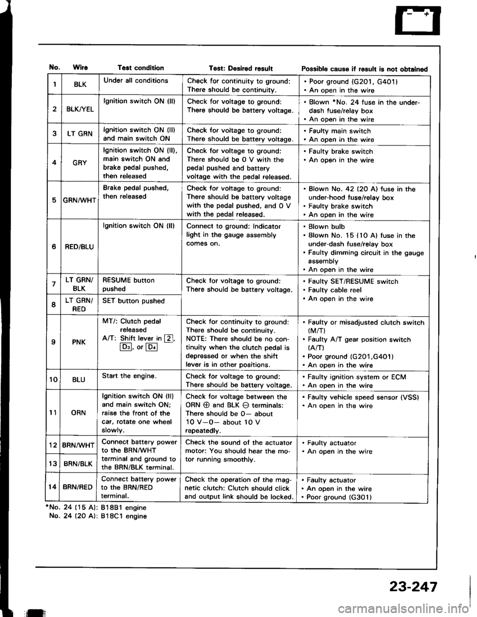
tlo.WlfeTost condition
*No. 24 (15 Al: 81881 engine
No.24 l2O A): 818C1 engine
Tost: Desired rosultPossibl6 caus€ it losult is not obtained
IBLKUnder all conditionsCheck for continuity to ground:
There should be continuitv.
. Poor ground (G201, G4011. An open in the wire
2BLKryEL
lgnition switch ON (ll)Check for voltage to ground:
There should be battery voltage.
. Blown rNo. 24 fuse in the under-
dash fuse/relay box. An open in the wire
5LT GRNlgnition switch ON (ll)
and main switch ON
Check for voltage to ground:
There should be battery volt€ge.
. Faulty main switch. An open in the wire
4GRY
lgnition switch ON lll),main switch ON and
brake pedal pushed,
then released
Check for voltage to g,ound;
There should be O V with thepedal pushed and battery
voltage with the pedal released,
. Faulty brake switch. An open in the wire
GRN/wHT
Brake pedal push€d,
then r€leased
Check tof voltage to ground:
There should be battery voltage
with the pedal pushed, and O V
with the Dedal released.
Blown No. 42 l2O Al tuse in the
under-hood fuse/relay box
Faulty brake switch
An open in the wire
6RED/BLU
lgnition switch ON (ll)Connect to ground; Indicator
light in the gauge assembly
comes on.
Blown bulb
Blown No. 15 (10 A) fuse in the
under-dash fuse/relay box
Faulty dimming circuit in the gauge
assembly
An open in the wire
7LT GRN/
BLK
RESUME button
pushedCheck for voltage to ground:
There should be battery voltage.
Faulty SET/RESUME switch
Faulty cable reel
An open in the wire6LT GRN/
RED
SET button pushed
qPNK
MT/: Clurch pedal
released
A/T: Shift l€ver in [Zl,
lD:I, or lE.l
-
Check for continuity to ground:
There should be continuity.
NOTE: There should be no con-
tinuity when the clutch pedal is
depressed or when the shift
lever is in other positions.
Faulty or misadiusted clutch switch(M/T)
Faulty A/T gear position switch(A/T)
Poor ground (G201 ,G4O1)An open in the wire
10BLUStart the engine.Chsck for voltage to ground:
There should be battery voltage.
. Faulty ignition system or ECM. An open in the wire
11ORN
lgnition switch ON (ll)
and main switch ON;
rsise the front of the
car, rotat€ one wheel
slowly.
Check Jor voltage between the
ORN @ and BLK O terminals:
There should be O- about
10 V-O- about 1O V
repeatedly.
. Faulty vehicle speed sensor (VSSI. An oDen in the wire
'128RN/WHTConnect battery power
to the BRN/WHT
terminal and ground to
the BRN/BLK terminal.
Check the sound of the actuator
motor: You should hear the mo-
tor running smoothly.
. Faulty actuator. An opsn in the wire
13BRN/BLK
14BRN/RED
Connect battery power
to the BRN/RED
terminal.
Check the operation of the mag-
netic clutch: Clutch should click
and output link should be locked.
Faulty actuator
An open in the wire
Poor ground (G3O 1)
il:
23-247