Electrical HONDA INTEGRA 1994 4.G User Guide
[x] Cancel search | Manufacturer: HONDA, Model Year: 1994, Model line: INTEGRA, Model: HONDA INTEGRA 1994 4.GPages: 1413, PDF Size: 37.94 MB
Page 208 of 1413
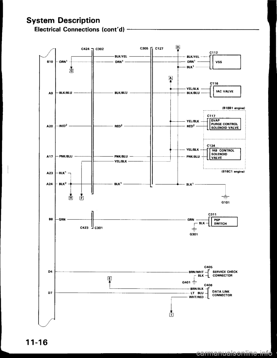
System Description
Electrical Connections (cont'dl
BLI(/YEL
oRI{r
il ".t ttlenn __JlF-----l
ll r Brx_Ll swrcH Ic423 ! caor -L
e s-ot
c405
eaurvxr Jr BLK -l
1-G401 :-
SERVICE CHECKCOIIIIECTOR
DATA LINKcorrttIEcToR
- c40aBRN/BLK fLT BLU IWHT/RED {
BTKiYEL-JT---l
oR 1 ----l I vss IBLK' {l I
c't 16
v:r-,sr-* -J l-----]".*,".u {l
'o" uo.u. I
lA18a1 ongine,
lB18C1 6ngin€)
11-16
Page 210 of 1413
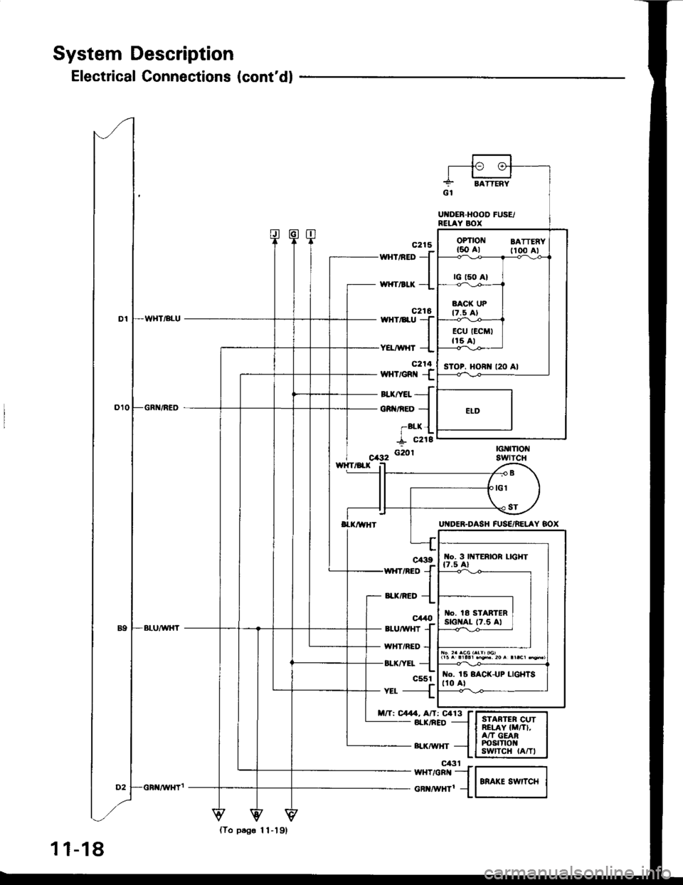
System Description
Electrical Connections (cont'dl
160 Al fioo Al
sToP. HORI{ t20 Al
wnrneo
J
,*rr"a* -l
c216wHr/8ru TIYEL/WHT --L
c214wHvem {
auryet{
oR nED -l
-alx {
I "rti'f_ c218
G20r
wxrneo {
"a*,"ao {
c44t)*utwxr
{wHriRED --l
or-rrv:r- {c551-{
nft C4. Af,: Ca13 f- 8rr(/nED -l
- surwxr -{
I{o. 3 lttTERlOR LIGHT
l|5^.llll.n'i'20r!|.c1q*,
o. la STARTERstGI{At- t7.5 Al
No. 15 8ACK-UP LIGHISt10 al
{To ptg€ 11-19,
1 1-18
el3t Fw{T/GRr{ _-]
cR ^i|Hrl 1
Page 225 of 1413
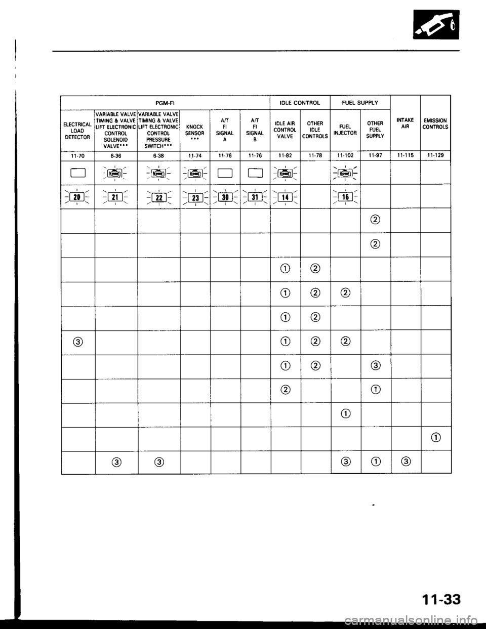
PGM-FIIOLE CONTROLFUEL SUPPLY
INTAKEAIR€MtsstoNCONTROLSELECTRICALLOAODETECTOR
VARIAEIE VALVETIMINC & VALVELIFT ELECTRONICcoNTRO|-SOLENOID
VARIABLE VALVETIMING & VATVEI-IFT ILECTRONICcottTR0tPffESSURE
KNOCKstNsoRFISIGNALFISIGNAT
IOLE AIRc0NTR0r-OTHERIOLECONTROLS
FUELINJECTOR
OTHERFUELSUPPTY
| 1"70s3811.74r 1-76t 1-7611-8211-78| 1-102r 1-97t 1-1 15ll129
Er6t-- -------16l-/-----..Efl-o_,.''\
\.-r-l-t l0 t----i-\t2t I/ --i-\
\-!-/
l22 l/-- j--\t23 l-/--.i-\-t 30 l-,--T-\
\.--r-z
t3r t-/-.--\
\.---l
[|-/----\I 16 t-/ _-i- \
@
@
o@
o@@
oQ)
@a,@@
o@@
@o
o
(JJ
@@@o@
11-3
Page 228 of 1413
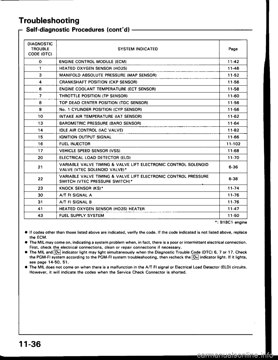
Troubleshooting
Self-diagnostic Procedures (cont'dl
':818C1 engine
a lf codes other than those listed above are indicated, verifv the code. lf the code indicated is not listed above, replace
rhe ECM.
a The MIL may come on, indicating a system problem when, in fact, there is a poor or intermittent electricalconnection.
First, check the electrical connections, clean or repair connections it necessary.
o The MIL and @ indicator light may light simultaneously when the Diagnostic Trouble Code (DTC) 6, 7 or 17. Check
the PGM-Fl system according to the PGM-Fl system troubleshooting, then recheck the l!! indicator light. ll it lights,
see page 14-5O, 51.
a The MIL does not come on when there is a malfunction in the A/T Fl signal or Electrical Load Detector (ELDI circuits.
However, it will indicate the codes when the Service Check Connector is shorted.
DIAGNOSTIC
TROUBLE
CODE (DTCISYSTEM INDICATEDPsge
oENGINE CONTROL MODULE IECM)11-42
,lHEATED OXYGEN SENSOR IHO25)1 1-46
aMANIFOLD ABSOLUTE PRESSURE {MAP SENSOR)11-52
4CRANKSHAFT POSITION (CKP SENSOR)1 1-56
oENGINE COOLANT TEMPERATURE (ECT SENSOR)11-58
THROTTLE POSITION (TP SENSOR}11-60
ITOP DEAD CENTER POSITION (TDC SENSORI1 1-56
9No. 1 CYLINDER POSITION (CYP SENSOR)1 1-56
10INTAKE AIR TEMPERATURE (IAT SENSOR)11-62
13BAROMETRIC PRESSURE (BARO SENSOR}1|-64
14IDLE AIR CONTROL (IAC VALVE}11-42
tcIGNITION OUTPUT SIGNAL11-66
toFUEL INJECTOR1't-102
17VEHICLE SPEED SENSOR {VSSI11-68
20ELECTRICAT LOAD DETECTOR (ELD)'t 1-70
21VARIABLE VALVE TIMING & VALVE LIFT ELECTRONIC CONTROL SOLENOID
VALVE {VTEC SOLENOID VALVE)'6-36
22VARIABLE VALVE TIMING & VALVE LIFT ELECTRONIC CONTROL PRESSURE
SWITCH (VTEC PRESSURE SWITCHI-6-38
23KNOCK SENSOR {KS}-11-7 4
30A/T FI SIGNAL A11-76
3'rA/T FI SIGNAL B1 1-76
4'lHEATED OXYGEN SENSOR (HO25} HEATER11-47
43FUEL SUPPLY SYSTEM1 1-50
11-36
Page 231 of 1413
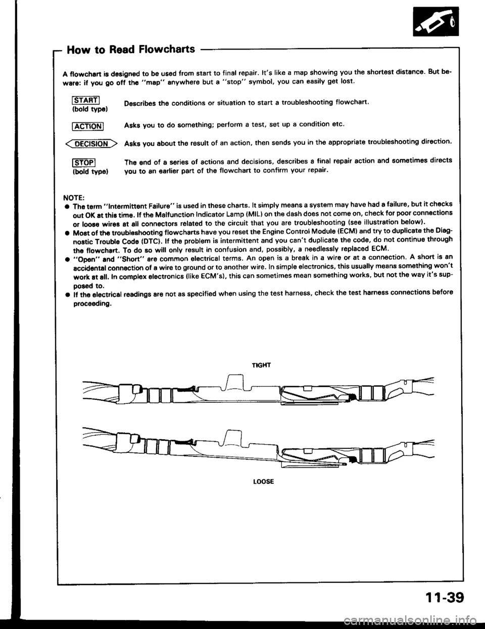
How to Read Flowcharts
A flowchrrt is dasigned to be us€d fiom start to final repair. lt's like a map showing you the shortest distanco. But be-
ware: if you go off tho "map" anywhere but a "stop" symbol, you can easily get lost
l6rffil Desclibas the conditions or situation to start a troubleshooting flowchart.(bold tyDo)
|TeTiONl Asks you to do something; pedorm a test, set up a condition etc'
<:6Eei6io-fr\> Asks you about the result of an action, then sends you in the appropriste troubleshooting direction.
I-SJTFI The snd of a series ot actions and decisions, describes I tinal repair action and aomotimea diracts
(bold typel you to 8n garlier part of the tlowchart to confirm your repair'
NOTE:
a Tha tarm ,,lntormittgnt Failure" is used in these chans. lt simply means a system may have had a failur6, but it chocks
out OK !t this time. lf th6 Msltunction Indicator Lamp (MlL) on ihe dash does not come on, check for poor connections
or loose wires at all connectors rolated to the cilcuit that you are troubleshooting (see illustration b6low).
a Most ot tho troublashooting flowchans have you reset the Engine Control Module (ECM) and try to duplicate the Disg-
nostic Troubls Cod6 (DTC). lf the problem is intermittent and you c8n't duplicat€ the cod6, do not continus through
the flowchart, To do so will only rosult in confusion and, possibly, a ne€dlessly replaced ECM
a ,,opon,'and ,,short,, are common electrical terms. An open is a break in a wir6 or at a conn€ction. A short is an
accidontal connaction ot a wir€ to ground or to another wire. In simple electronics, this usually means som€thing won't
work at all. In complex electronics (like ECM's), this can sometimes mean something wolks, but not the way it's sup-
poSad to,
a il th6 olectricsl readings are not as specified when using the test harness, check the test harness connoctions bsfore
procooding.
LOOSE
11-39
Page 244 of 1413
PGM-FI System
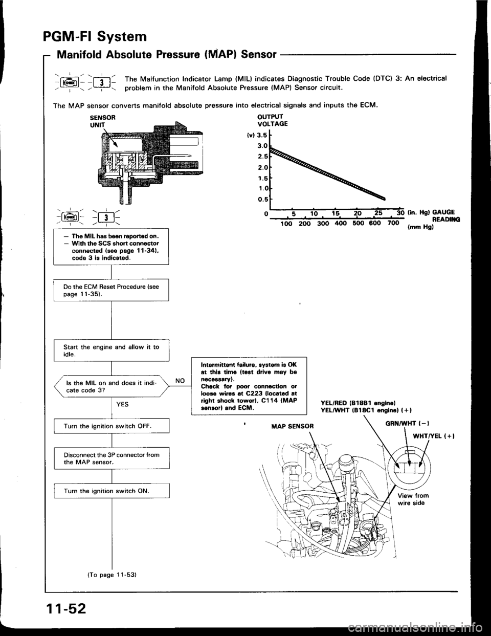
Manifold Absolute Pressure (MAP) Sensor
fxai - lfil1 The Malfunction Indicator Lamp (MlL) indicates Diagnostic Trouble Code (DTC) 3: An electrical
-:- -?- problem in the Manifold Absolute Pressure (MAPI Sensor circuit.
The MAP sbnsor converts manitold absolute pressure into electrical signals and inputs the ECM.
OUTPUTVOLTAGE
600 700
(in. Hsl GAUGEREADIIIO{mft Hg)
YEL/RED lBlSBl onginc)YEL^YHT lBlaCl .ngin.l | + I
{+l
SENSOR
1.5
- Tho MIL has boon roportod on.- Wirh tho SCS rhort connoctorconnectod lsoo pags 11-34),codo 3 b indicatsd.
Do the ECM Reset Procedure {soepage 11-35).
Intormittont tailuro, lystom ir Ol(at thls timo {tort drivo may bsnocessary).Chack to? Door connocllon oiloosa wiroa 6t C223 {locltod atright shock tow6rl, C'l 14 (MAP
sonaorl and ECM.
ls the MIL on and does it indi-cate code 3?
Turn the ignition switch OFF.
Disconnect the 3P connector tromthe MAP sensor,
Turn the ignition switch ON.
{To page 11-53)
11-52
Page 260 of 1413
![HONDA INTEGRA 1994 4.G User Guide PGM-FI System
Electrical Load Detector (ELDI
tft;-]/ The Maltunction Indicaror Lamp (MlL) indicatss Diagnostic Trouble Code IDTC) 20: A probtem in-Li!- tne Electrical Load Detecror {ELD} circuit.
With HONDA INTEGRA 1994 4.G User Guide PGM-FI System
Electrical Load Detector (ELDI
tft;-]/ The Maltunction Indicaror Lamp (MlL) indicatss Diagnostic Trouble Code IDTC) 20: A probtem in-Li!- tne Electrical Load Detecror {ELD} circuit.
With](/img/13/6067/w960_6067-259.png)
PGM-FI System
Electrical Load Detector (ELDI
tft;-]/ The Maltunction Indicaror Lamp (MlL) indicatss Diagnostic Trouble Code IDTC) 20: A probtem in-Li!- tne Electrical Load Detecror {ELD} circuit.
With lho SCS lhon connectolconnoctod {ree pago 11-34}, cod.20 is indicatod.
Do the ECM B6set Procedurs {seepage 1 'l-35).
Start engine and keep engin€speed at idle.Turn on headlights.
lntennlna tlllure, lyrtom lt Ol(!t irl. dm. (lgtt driv. mly [email protected] for Door connactlona oaloota wiro. rt C218 IELD, lndEctrt.
Ooes the MIL indicato code 20?
Romove the undgr-hood fusg/relay box and remove the tus6/relav box lowet cover.
Turn lhe ignition switch ON.
Measure voltage betw€on BLK/YEL (+l terminal and BLK (-)terminal.
Msasuro voltag€ b€tweon BLK/Y€L {+) terminal snd bodvground.ls there bartory voltagel
Rcpir oo.n in BLK wir.batwaan lha 3P connrc-tor lnd G2Ol {loc.t.dtroit ot angh|. comprn-m.r dghl .ld.l,
B.p.lr op.n in BLKrYEL wlrr b.-tw..n o.24ACG (ALn flcl115A: Bl88l .ngln!, 20 A:818C1cnginol fu!. In thr und.r{..htu.o/r.lly bor lnd tho 3P con-rcclo?.
View tromwire side
BLK (-)
(To page 11-7'l)
GRn/iED I - |
BLK/YEL I + I
11-70
Page 262 of 1413
PGM-FI System
11-72
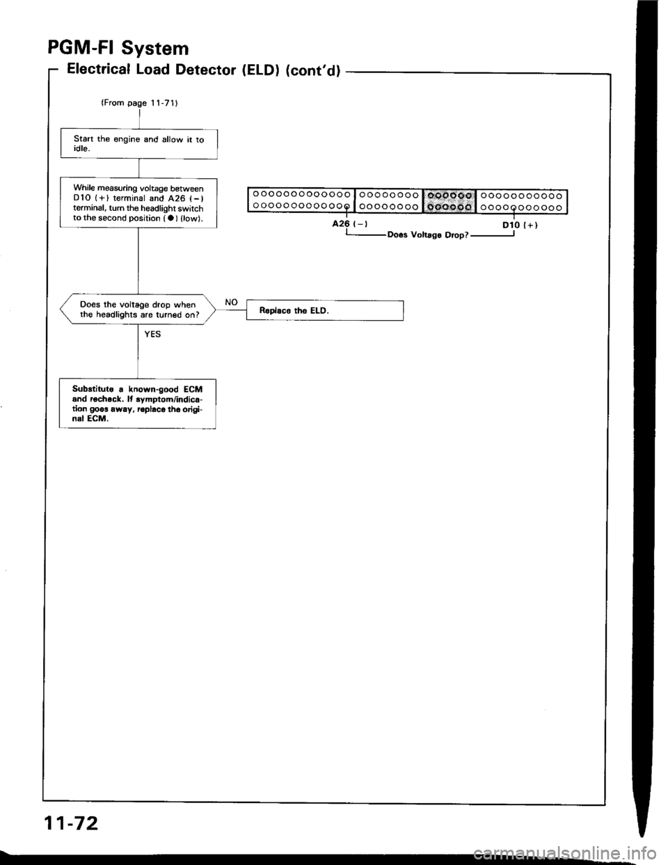
While measuring voltage betweenDlO 1+) terminal and 426 l-)terminal, turn the headlighr switchto the second position (a) {low).
Does the voltage drop whenthe headlights are turned on?
Subrtitute . known-good ECMand rochock. lt 3ymptom/indic€-tion goos away, ioplaco th6 origi-nal ECM.
Electrical Load Detector (ELD) (cont'd)
425 t-t D10 l+), Doos Volrago Orop? ----------------J
Page 393 of 1413
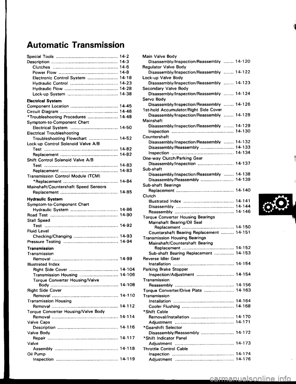
Automatic Transmission
'l4-2
14-3't 4-6
14-8
14-14
14-23
Hvdraulic Flow ...--...... 14-24
Lock-up System ........ 14-38
Eloctrical Systom
Component Location ............,...,................ I 4-45
Circuit Diagram ............. 14-46'Troubleshooting Procedures ........,..........., l4-48
Symptom-to-Component Chart
Electrical System ...... 14-50
Electrical Troubleshooting
Troubleshooting Flowchart .................... 14-52
Lock-uo Control Solenoid Valve A/8
Test .................. --.... \4-82
ReDlacement ,...,...,..,. 14-82
Shift Control Solenoid Vslve A/B
Test .................. ...... 14-83
Reolacement .............. 14-83
Transmission Control Module (TCM)*ReDlacement ........... 14-84
Mainshalt/CountershaJt SDeed Sensors
Reolacement ............. 14-85
Hydraulic Systom
Symptom-to-Component Chart
Hydraulic System
Road Test
Slall Speed
Test ..................
Fluid Level
Checking/Changing
Pressu.e Testing
Transmission
Transmission
Removal ............. ...... 14-99
lllustrated Index
Right Side Cover .................................. 1 4- 1 04
Transmission Housin9 ..................,,....... I 4-1 06
Torque Converter HousingNalve
Body .................. ... 14- 1O8
Right Side Cover
Removal ............. ...... 14-110
Transmission Housing
Removal ............. .-..-. 14-112
Torque Convener HousingNalve Body
Removal ............. ...... 14-114
Valve Caps
Description ................ 14-116
Valve Body
Repair ................ ...-.. 14-117
Valve
Assembly ...........
Oil Pump
Main Valve Body
Disassembly/lnspection/Reassembly
Regulator Valve Body
Disassembly/lnspection/Reassembly
Lock-up Valve Body
Disassembly/lnspection/Reassembly .......
Secondary Valve Body
Disassembly/lnspection/Reassembly .......
Servo Body
Disassembly/lnspection/Reassembly .......
1st-hold Accumulator/Right Side Covet
Oisassembly/lnspection/Reassembly .,..,..
Mainshaft
Disassembly/lnspection/Reassembly -.. -... 1 4- 1 29
lnsDection ................. 14- 130
Countershaft
Disassembly/lnspection/Reassembly ....... 14-132
Disassembly/Reassembly ....................... 1 4-1 33
lnsDection ................. 14-134
One-way Clutch/Parking Gear
Disassembly/lnspection .................... -.. -. 1 4-137
Sub-shaft
Disassembly/lnspection/Reassembly ....... 14-138
Disassemblv/Reassemblv ....................... 1 4-1 39
Sub-shaft Bearings
Replacement ............. l4-140
Clutch
fllustrated lndex ................. -..-...-.......... 14-1 41
Disassembly ,,,.,,........ 14-144
Reassembly .............. 14-146
Torque Converter Housing Bearings
Mainshaft Bearing/Oil Seal
Reolacement ......... 14-1 50
Countershaft Bearing Replacement .......,, 14-1 5l
Transmission Housing Bearings
Mainshsft/Countershaft Bearing
Repfacement ...-..-..14-152
Sub-shaft Bearing Replacement .............. 1 4-1 53
Reve.se ldler Gear
lnstallation ................ 14-154
Parking Brake Stopper
lnspection/Adjustment ..........................'14-'154
Transmission
Reassemblv .............,. .14_156
Toroue Converter/Drive Plate ..,..,............... 1 4- 1 63
Transmission
14-120
14-122
14-123
14-124
14-126
14-124
14-86
14-90
't4-92
14-93
14-94
lnstallation
Cooler Flushing'Shitt Cable
Removal/lnstallation ..............................
Adiustment ...-..-......-. 14-'171*Gearshift Selector
Disassembly/Reassembly .....................,. 1 4-17 2*Shift Indicator Panel
Adjustment -..........-...14-173
Throttle Control Cable
fnspection .......,..,...... 14-17 4
Adjustment .............. 14-176
14-164
14-168
14-'t 7 0
Inspection
Page 442 of 1413
![HONDA INTEGRA 1994 4.G User Guide Symptom-to-Component Chart
Electrical System
Number of @indicator light
blinks while
Service Check
Connector is
connected with
the special tool.
@] indicaror
lightPossible CauseSymptomRefer to
page
Bl HONDA INTEGRA 1994 4.G User Guide Symptom-to-Component Chart
Electrical System
Number of @indicator light
blinks while
Service Check
Connector is
connected with
the special tool.
@] indicaror
lightPossible CauseSymptomRefer to
page
Bl](/img/13/6067/w960_6067-441.png)
Symptom-to-Component Chart
Electrical System
Number of @indicator light
blinks while
Service Check
Connector is
connected with
the special tool.
@] indicaror
lightPossible CauseSymptomRefer to
page
BlinksDisconnected lock-up control solenoidvalve A connector
Short or open in lock-up control sole-noid valve A wire
Faulty lock-up control solenoid valve A
Lock-up clutch does not
engage.
Lock-up clutch does not
disengage.
Unstable idle speed.
14-52
BlinksDisconnected lock-up control solenoidvalve B connector
Short or open in lock-up control sole-noid valve B wire
Faulty lock-up cont.ol solenoid valve B
. Lock-up clutch does not
enga9e.
14-54
Blinks or
OFF
Disconnected throttle position (Tp)
sensor connector
Short or open in TP sensor wireFaully TP sensor
. Lock-up clutch does not
engage.14-56
4BlinksDisconnected vehicle speed sensor(VSS) connector
Short or open in VSS wire
Faulty VSS
. Lock-up clutch does not
engage.'t 4-57
Blinks. Short in A/T gear position switch wire. Faulty A/T gear position switch
. Fails to shift other than
2nde4th gears.. Lock-up clutch does not
engage.
14-58
OFFDisconnected A/T gear position switch
connector
Open in A/T gear position switch wireFaulty A/T gear position switch
Fails to shift other than
2nd-4th gears.
Lock-up clutch does not
en98ge.
Lock-up clutch engages
and disengages alter-
nately.
14-60
7BlinksDisconnected shift control solenoidvalve A connector
Short or open in shitt control solenoidvalve A wire
Faulty shift control solenoid valve A
. Fails to shift (between
1st-4th, 2nd-4th or
2nd-3rd gears only).. Fails to shift (stuck in
4th gear).
14-62
8BlinksDisconnected shitt control solenoid
valve B connector
Shon or open in shift control solenoidvalve B wi.e
Faulty shift control solenoid valve B
. Fails to shiJt (stuck in
lst or 4th gears).'t 4-64
aBlinksDisconnected countershatt speed sen-sor connector
Short or open in the countershaft
speed sensor wire
Faulty countershaft speed sensor
. Lock-up clutch does not
engage_
14-50