Electrical HONDA INTEGRA 1994 4.G Repair Manual
[x] Cancel search | Manufacturer: HONDA, Model Year: 1994, Model line: INTEGRA, Model: HONDA INTEGRA 1994 4.GPages: 1413, PDF Size: 37.94 MB
Page 1195 of 1413
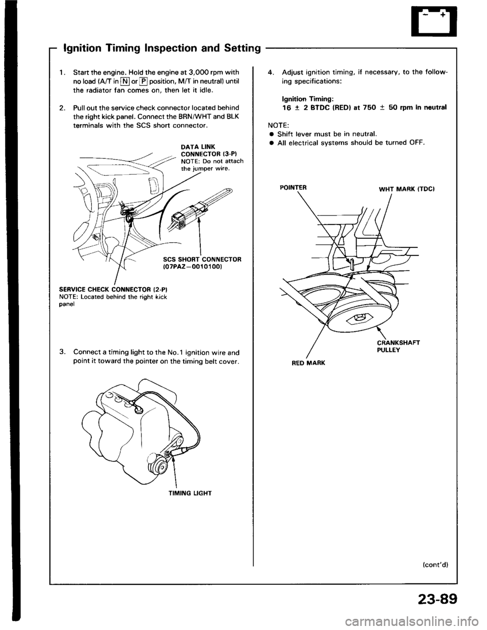
lgnition Timing Inspection and Setting
1.Start the engine. Hold the engine at 3,00O rpm with
no load (A/T in S or E position, M/T in neutral) until
the radiator fan comes on, then let it idle.
Pull out the service check connector located behind
the right kick panel. Connect the BRN/WHT and BLK
terminals with the SCS short connector.
4. Adiust ignition timing, if necessary, to the follow-
ing specifications:
lgnition Timing:
16 t 2 BTDC (RED) at 75O 1 50 rpm in noutral
NOTE:
a Shift lever must be in neutral.
a All electrical systems should be turned OFF.DATA LINKCONNECTOR {3-P}NOTE: Do not attachthe jumper wire.
POINTER
SCS SHORT CONNECTOR{0?PAZ-O010't 00t
SERVICE CHECK CONNECTOR I2.PINOTE: Located behind the right kickoanel
Connect a timing light to the No.1 ignition wire andpoint it toward the pointer on the timing belt cover.
TIMING LIGHT
lcont'd)
REO MARK
23-89
Page 1196 of 1413
lgnition System
lgnition Timing lnspection and
Setting (cont'd)
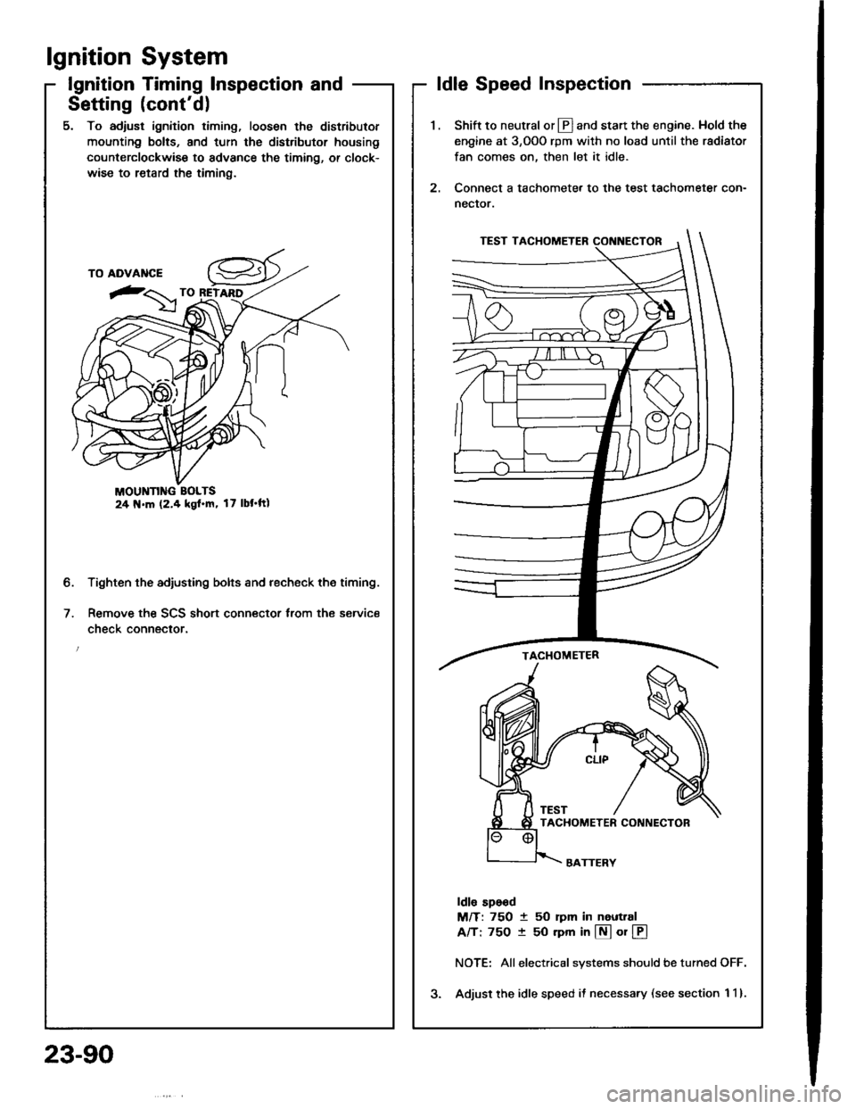
5. To adjust ignition timing, loosen the distributor
mounting bolts, and turn the distributor housing
counterclockwise to advance the timing, or clock-
wise to retard the timing.
MOUNN G BOLTS24 N.m (2.4 kgl.m, 17 lbt'ftl
Tighten the adjusting bolts and recheck the timing.
Remove the SCS short connector trom the service
check connector.
2.
ldle Speed Inspection
Shift to neutral or Ll] and start the engine. Hold the
engine at 3,OOO rpm with no load until the radiator
fan comes on, then let it idle.
Connect a tachometer to the test tachometer con-
nector.
ldle sp6od
M/T: 750 t 50 rpm in neuttal
A/T: 75O t 50 rpm in @ or @
NOTE: Allelectrical systems should be turned OFF.
Adjust the idle speed il necessary (see section 1 1).
b.
23-90
Page 1204 of 1413
Charging System
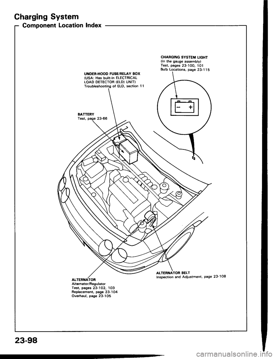
Component Location lndex
UI{DER.HOOD FUSE/BELAY BOX(USA: Has builr-in ELECTRICALLOAD DETECTOR {ELD) UNIT)Troubleshooting ot ELD, s€ction 11
BATTERYTost,
CHARGING SYSTEM LIGHTlln the gauge sssemblylT€st. pages 23-1OO. 101Bulb Locations, page 23-1 1 5
ALTERNATOR BELTInspoction and Adiustment, page 23-108
Alt6rnator/RegulatorTosl, pag€s 23-102, 1O3Replacament. page 23-'l 04Ovsrhaul, pago 23-105
23-98
Page 1208 of 1413
Charging System
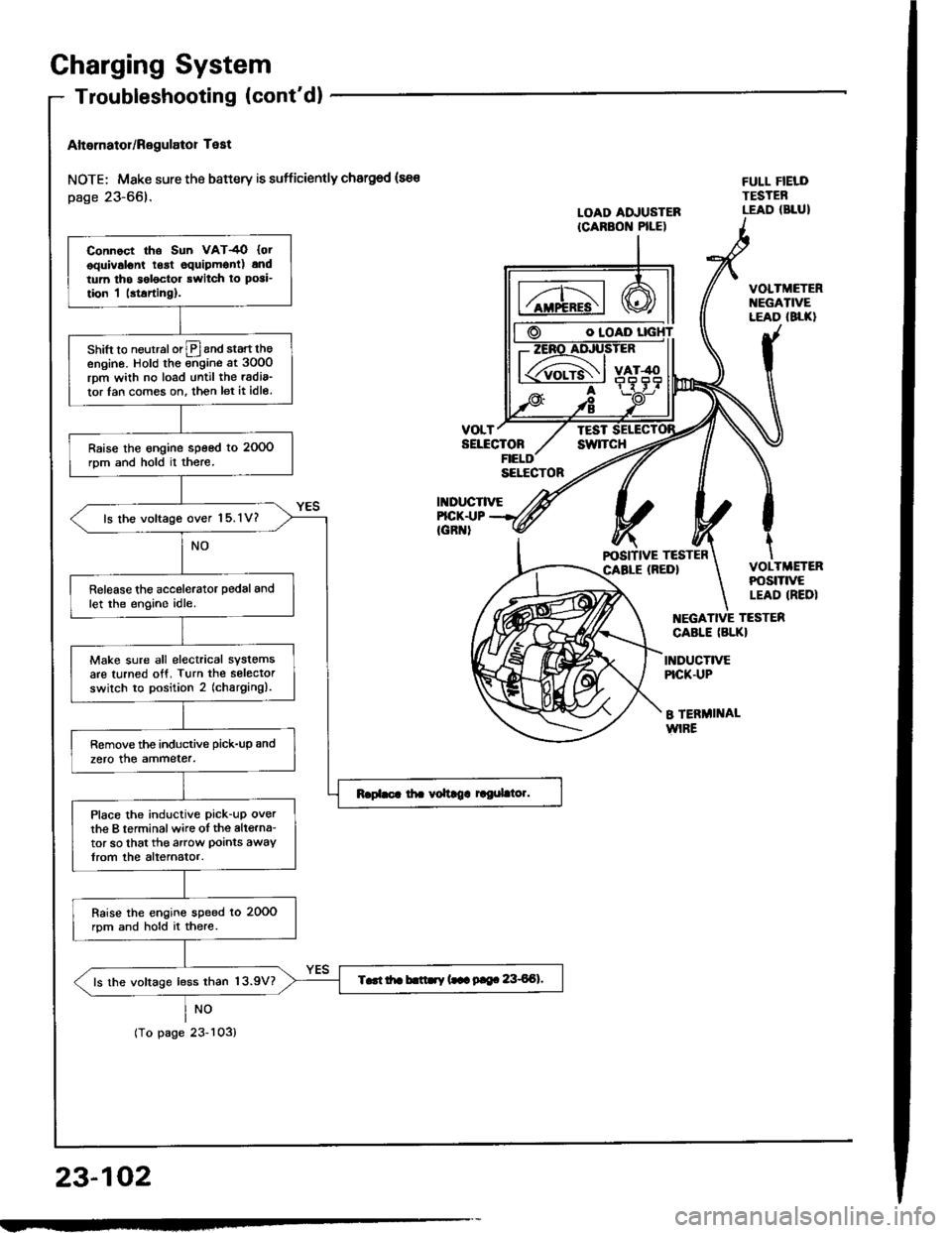
Altornator/Regulator Test
NOTE; Mske sure the battery is sufficiently chargod (sa€
page 23-66).
NO
tropagezJ-ruJ,
O IOAD
VOLTTESTSELECTONswlTcH
II{DUCTIVE
FULL FIELDTESTEBLEAD (BLUILOAD ADJUSTERICARBON PILE)
FICK.I.|PIGR '
VOLTMETERt{EGATIVELEAD (8LK}
VOLTMETERPOStTtVELEAD IREDI
EGATIVE TESTER
CABLE (BLKI
INDUCTIVEPICK.UP
B TERMI]TALWIRE
23-102
Connoct tho Sun VAT4O {otooulvslont lgrt equipmonl) andtum tho s6l6ctor rwitch ro posi_
tion I |rtarting).
shift to neurralorlPland start theengino. Hold the ;;gine at 3oO0rpm wiih no load until the radia_
tor lan com€s on. then let it idle.
Raise the engine speed to 2OOOrom and hold il there.
ls lhe voltage over 15.1V?
Release the accelerator pedal andlet the engino idle.
Make sure all electrical systemsare turned otf. Turn the selectorswilch to position 2 (charging).
Remove the inductive pick-up and
zero the ammeter.
Place the inductive pick-uP overthe B terminalwire oI the altgrna-tor so that the arow Doints awaytrom the alternator.
Raise the engins speed lo 20OOrpm and hold it there.
T..t itr b.ttry (.- 9|e. 8€Al.ls the voltage less than 13.9V?
Page 1219 of 1413
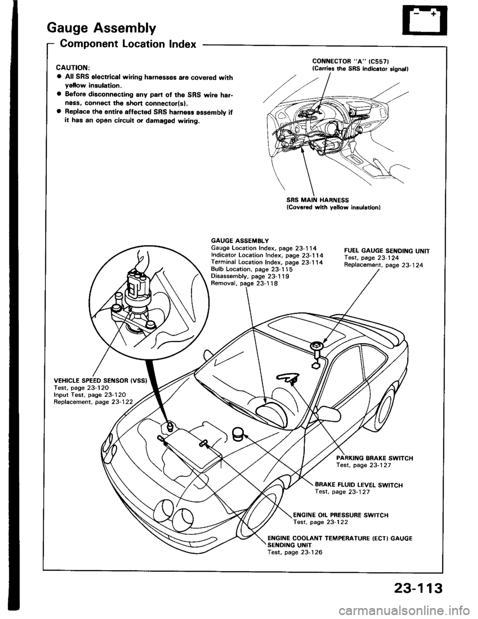
Gauge Assembly
Component Location Index
CAUTION:
a All SRS electrical wiring harnosses are cov€rod withyellow insulation.
a Bofore disconnecting any prn ot th€ SRS wire har-ness, connect tho short connector(sl.a R€place th6 entirs affGcted SRS halne$ assembly ifit has an open circuit o? damaged wiring.
SRS MAIN HARNESS{Cov.r6d with yollow inrularionl
GAUGE ASSEMBLYGauge Location Index, page 23-114Indicator Location Index, page 23-1 14Terminal Location Index, page 23-114Bulb Location. page 23-'l 15Disassembly. page 23-1 19Removal, page 23-118
FUEL GAUGE SENDING UNtTTest, page 23'124Repfacemenr, page 23-124
VEHICLE SPEEO SENSOB IVSS}Test, page 23-120fnput Test. page 23-120Repfacement, page 23-122
PARKITTG BRAKE SWITCHTest, page 23-127
BRAKE FLUID LEVEL SWITCHTesr, page 23-127
EI{GINE OIL PBESSURE SWITCHTest, page 23-122
ENGINE COOLANT TEMPERATURE IECTI GAUGESENOING UNITTest, page 23-126
(C61'ios tho SBS indicator signal)
23-113
Page 1224 of 1413
Gauge Assembly
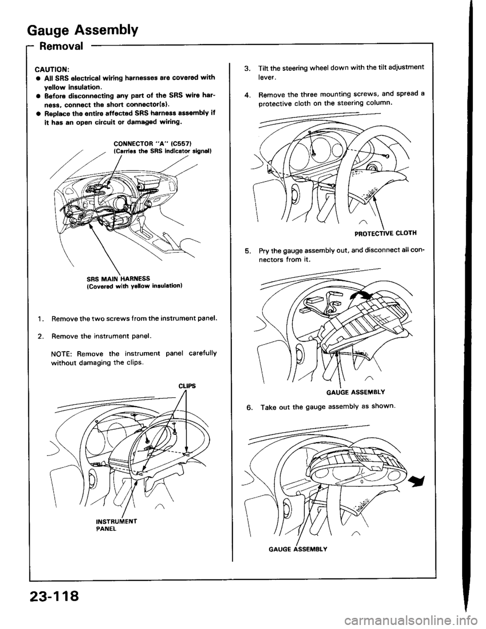
Removal
CAUTION:
a All SRS electrical wiling harnesses ara cover6d with
yollow insulation.
a Eofore disconnecting any part ol the SRS wiro har-
n6ss, connoct lhe short connector(sl.
a Roplace tho entirs affocted SRS harneas assembly if
it has an open circuit 01 damaged wi.ing.
SBS MAIN HARI{ESS(Covor6d with Yollow in.ulationl
Remove the two screws lrom the instrument panel.
Remove the instrument panel.
NOTE: Remove the instrument panel careJully
without damaging the cliPs.
1.
2.
lcarrio. tho SRs indicolor 8ignal)
CLIPS
23-118
Tilt the steering wheel down with the tilt adjustment
tevet.
Remove the three mounting screws, and spread a
protective cloth on the steering column.
PROTECTIVE CLOTH
Pry the gauge assembly out, and disconnect allcon-
nectors from it.
GAUGE ASSEMBLY
Take out the gauge assembly as shown.o.
Page 1240 of 1413
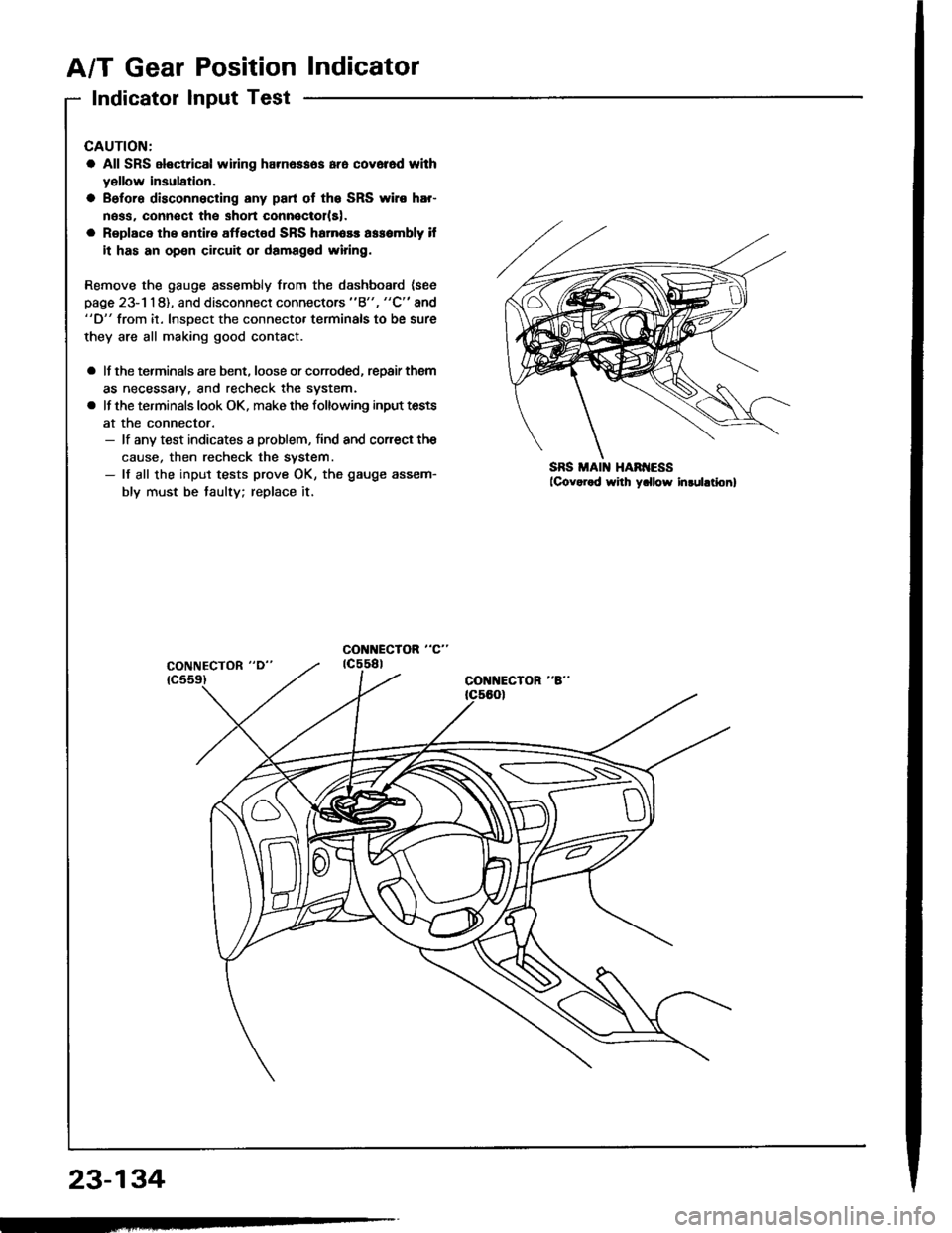
A/T Gear Position Indicator
Indicator Input Test
CAUTION:
a All SRS electrical widng harn6ssos ara cov6r6d whh
yellow insulation.
a Before disconnecting any part ot the SRS wiro hEr-
ness. connect the shon connoctolls).
a Replace the entire affectod SRS harnosr assombly il
it has an op€n circuit or damaged wiring.
Remove the gauge assembly from the dashboard (see
page 23- l 1 8), and disconnect connectors "8", "C" and"D" from it. lnsoect the connecto. terminals to be sure
they are all making good contact.
a lf the terminals are bent. loose or corroded, repair them
as necessary, and recheck the system.
a lf the terminals look OK, make the following input tests
at the connector.- lf any test indicates a problem, find and corect the
cause, then recheck the system.- lf all the input tests prove OK, the gauge assem-
bly must be taulty; replace it.
CONI{ECTOR "8"
SS
23-134
Page 1244 of 1413
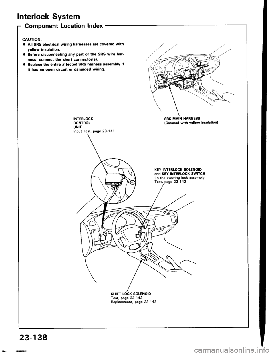
Interlock System
Component Location Index
All SRS electrical wiring harnass€s are covered with
yallow insulation.
Before disconnecting any part of the SRS wire har-
ness, connect the shon connector(sl.
Replace the entire affected SRS halness ass€mbly it
it has an open circuit or damaged wiring.
INTERLOCKCONTROLUNITfnput Test, page 23-141
SRS MAI[{ HARNESS
lcovorod with yellow insulstionl
SHIFT LOCK SOLENOIOTest, page 23- 143Repfacement, page 23-1 43
KEY INTERLOCK SOLENOIDsnd KEY INTERLOCK SWITCH(ln the steering lock assembly)Test, page 23-142
23-138
Page 1248 of 1413
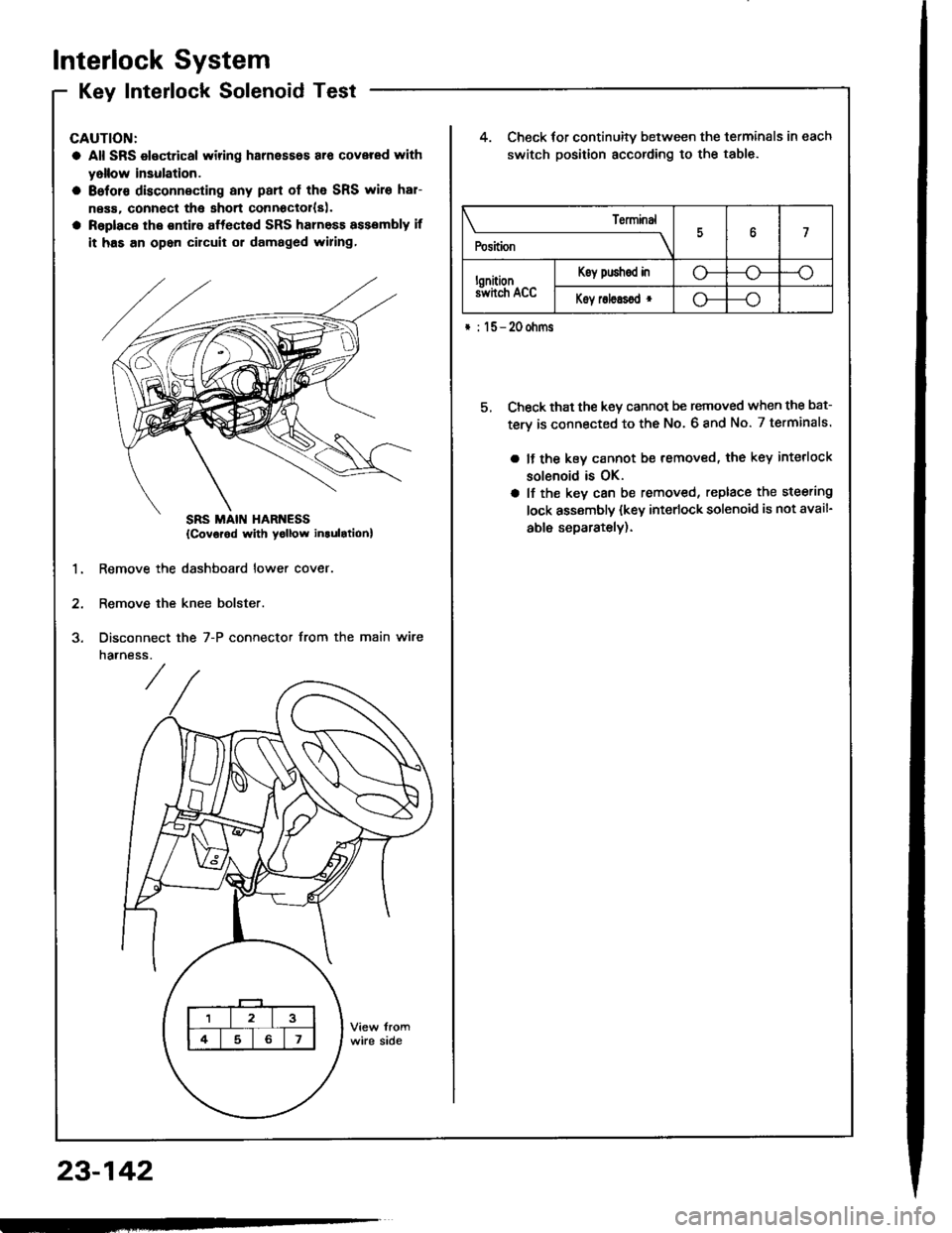
Interlock System
Kev Interlock SolenoidTestKey IntenocK Dorenoro I esr -
CAUTION:
a All SRS electrical wiring harnesses ar€ covered rYith
yollow insulation.
a 8eforc disconnecting any pan of the SRS wire har-
ness. connecl tha short connoclol{s|.
a Raplace the ontire affected SRS harness assembly if
it has an opon circuit or damaged wiring,
4. Check for continuitv between the terminals in each
switch position according to the table.
5, Check that the key cannot be removed when the bat-
tery is connected to the No. 6 8nd No. 7 terminals.
a It the kev cannot be removed, the key interlock
solenoid is OK.
a lf the key can be removed, replace the steering
lock assembly (key interlock solenoid is not avail-
able separately).
1.Remove the dashboard lower cover
Remove the knee bolster.
Disconnect
narness.
the 7-P connector from the main wire
\______________rry
Position7
lonitionS hch Acc
Koy push€d ino---o
Koy roleEsod r--o
* : l5-20ohms
{Covorod with yollow inlulrtionl
23-142
Page 1290 of 1413
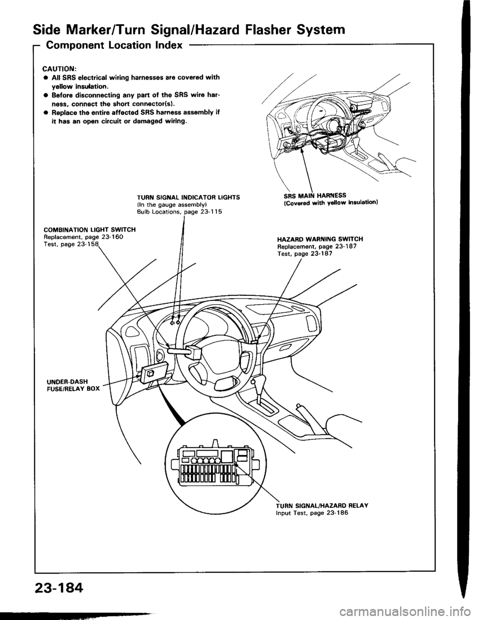
Side Marker/TurnSignal/Hazard Flasher System
Component LocationIndex
23-184
GAUTION:
a All SRS electrical wiring harnessos ar6 covered with
yellow insulation.
a Belor€ disconnocting any pan of the SRS wire har-
ngss, connoct the short connector{s).
a Rsplace tho 6ntir€ affect€d SRS harnoss sssembly il
it has an op€n cilcuit or damaged widng.
TURN SIGNAL INDICATOR LIGHTS(ln the gauge assembly)
SRS MAIN HARI{ESS(Cov.rod with Ysllow in3ulationl
Bulb Locations,23-115
COMBINATION LIGHT SWITCHReplacement, page 23-160HAZARD WARI{ING SWITCHReplacement, page 23-187Test, page 23-187
Test, page 23-1
UNDER-DASHFUSE/RELAY 8OX
TURN SIGNAL/HAZARO RELAYInput Test, page 23-186
-