connector or terminal HONDA INTEGRA 1994 4.G Repair Manual
[x] Cancel search | Manufacturer: HONDA, Model Year: 1994, Model line: INTEGRA, Model: HONDA INTEGRA 1994 4.GPages: 1413, PDF Size: 37.94 MB
Page 468 of 1413
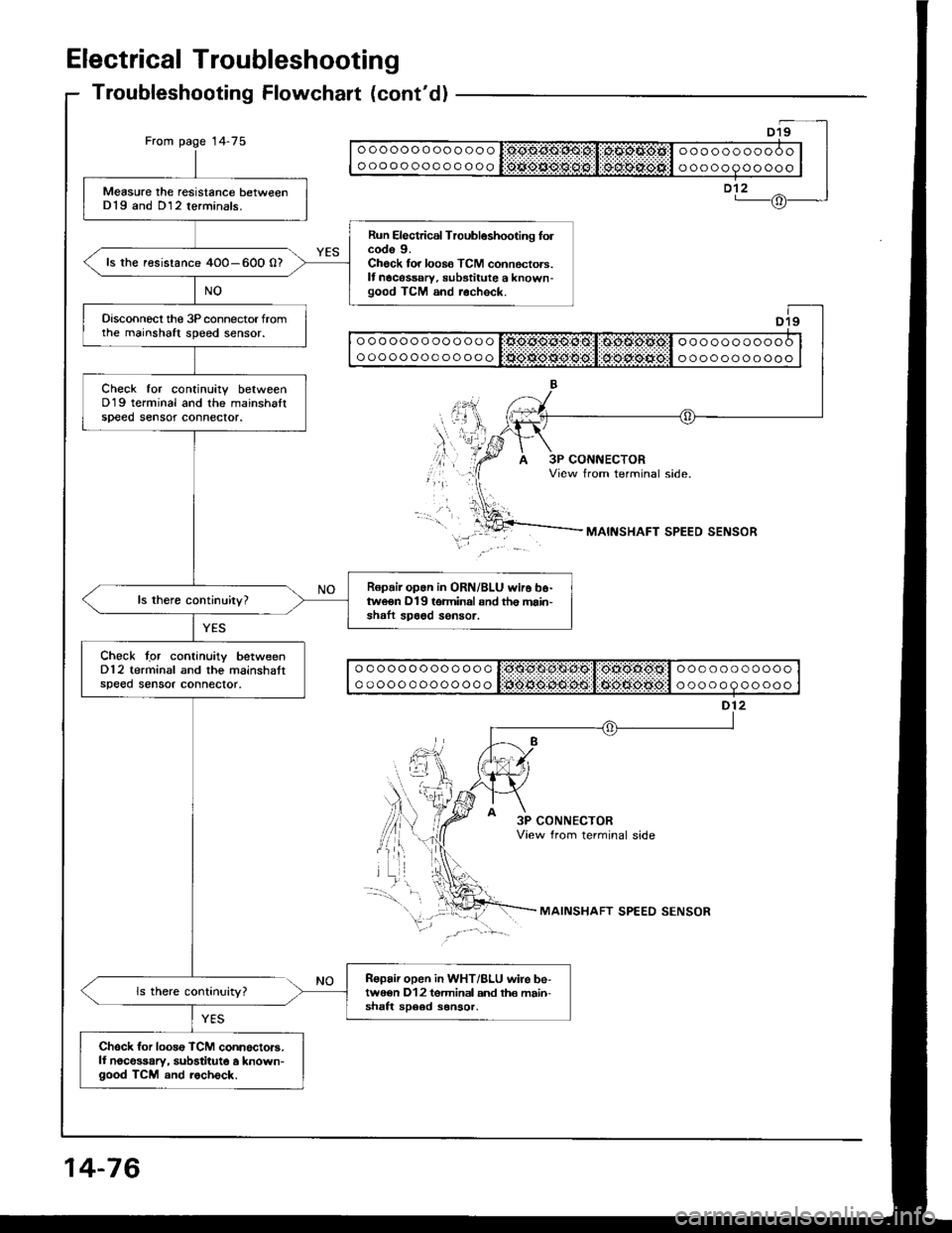
Electrical Troubleshooting
Troubleshooting Flowchalt (cont'd)
From page 14-75ooooooooooooo
oooooooooooooooooooooooo
ooooooooooo
Measure the resistance betweenD19 and D12 terminals.
Run Electrical Troubleshooting folcode 9.Check for loos6 TCM connectors.It nocessary, substitute a known-good TCM and r.check.
ls the resistance 4O0-600 0?
Disconnecl the 3P connector fromthe mainshaft speed sensor.
Check tor continuitv betweenD19 terminal and the mainshaltspeed sensot connector.
Ropair op.n in ORN/BLU wir6 b6-tweon D19 terminal snd th€ main'shaft spa6d sensor.
Chock tgr continuity betweenD12 terminal and the mainshattspeed sensor connector.
Ropair open in WHT/BLU wire be-twe€n D12 tgrminal and th€ main-shaft sD6ed sonsor.
Chsck for loos€ TCM connoctors.ll noco$ary, substitute a known-good TCM and rocheck.
ooooooooooooo
ooooooooooooooooooooooo
ooooooooooo
ooooooooooooo
ooooooooooooo
ooooooooooo
ooooooooooo
MAINSHAFT SPEED SENSOR
3P CONNECTORView from terminal side
MAINSHAFT SPEED SENSOR
14-76
Page 469 of 1413
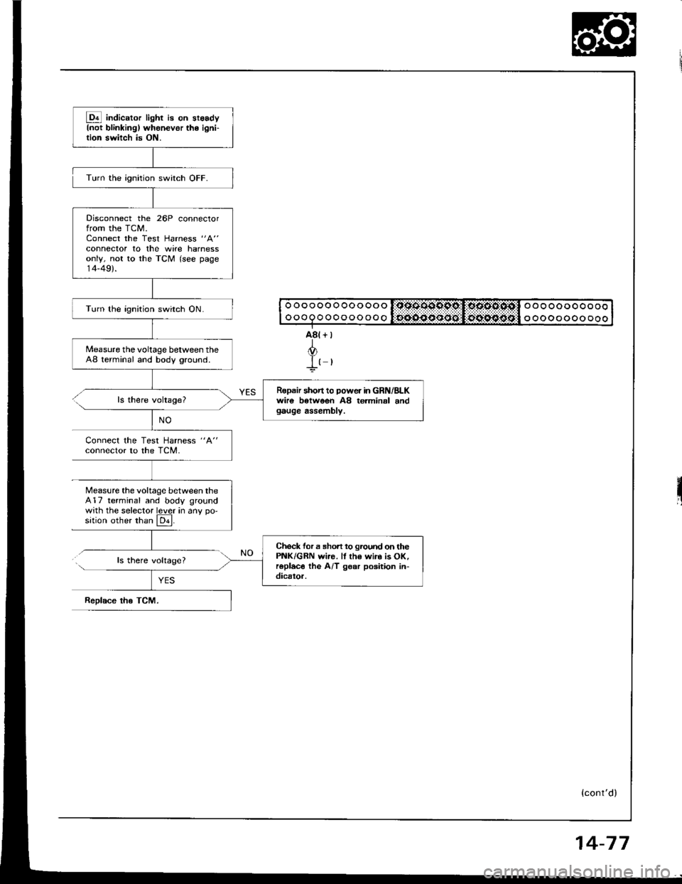
@ indic"to, light i8 on st6sdyInot blinkingl whenevor the ioni-tion switch is ON.
Disconnect the 26P connectorfrom the TCM.Connect the Test Harness "A"
connector to the wite harnessonly, not to the TCM (see page14-49).
Turn the ignition switch ON.
Measure the voltage between theA8 terminal and body ground.
Ropair shon to power in GRN/BLKwiro botwoen A8 terminal andgauge assembly.
Check for a sho.t to ground on thePNK/GRN wi.e. ll th€ wir. is OK,roplac€ the A/T gear poaition in-dicator.
Turn the ignition switch OFF.
ls there voltage?
Connect the Test Harness "A"
conneclor to the TCM.
Measure the voltage between the417 terminal and body groundwith the selector lever in anv oo'sition other than El.
ls there volrage?
ReDlace tho TCM.
o o o o oo o oo o oo o l:qssoo9pc,I:oocto:osil o o o oo o o o o oooooQoooooooooo oo o oooo ooo
{cont'd)
14-77
Page 470 of 1413
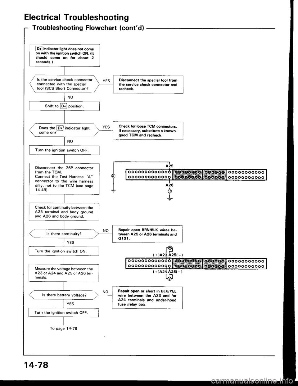
Electrical Troubleshooting
Troubleshooting Flowchaft (cont'dl
Does the @ indicatorcome on?
ls there baftery voltage?
YES
lighr
I A25
| | o ooooo o oo o ooo r:sjc.o.sl'1*st,li*os.s.4tcl ooo oo oooooo I
I I o o o o o o o o o o o o q lifrif.S..n${5git:li$gg-:aiiigitll o o o o o o o o o o o I|--.-T..-I a26
+d
+
I + )A23 A25l - l
(+ tA24 426(- |t\@
Lq4 indicator light do6s not comeon with the ignition switch ON. (ltshould come on Ior about 2seconds.l
ls the service check connectorconnected with the specialtool ISCS Short Connectod?
Diaconnect tho spocial tool fromth6 sgrvice check connoctor andrecheck.
Check {or loos6 TCM connoctors.lf necessaw, substitute a known-good TCM and recheck.
Turn the ignition switch OFF.
Disconnect the 26P connectorfrom the TCM.Connect the Test Harness "A"
conneclor to the wile harnessonly, not to the TCM (see page14-49).
Check for continuity between theA25 terminal and body groundand A26 and body ground.
R€pair open BRN/BLK wires be-twe6n A25 or A26 torminals andG 101.
Turn the ignition switch ON.
Measure the voltage between theA23 or A24 and A25 or A26 termrnals-
Repaii open or short in BLK/YELwire between tho A23 and /ot424 terminals and underhoodtuse /relav box.
Turn the ignition switch OFF.
To page 14-79
14-78
Page 471 of 1413
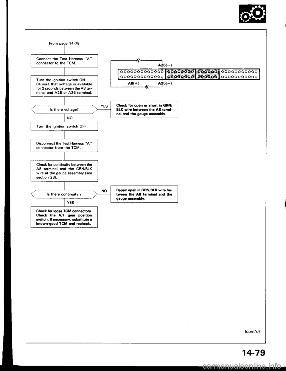
Connect the Test Harness "A"
connector to the TCM.
Turn the ignition switch ON.8e sure that voltage is availablefor 2 seconds between thg A8 tor-minal and A25 or A26 terminal.
Chrck for opon or rhort in GR /8LK wirc bctw.on th. A8 termi-nal and tha gauOa arrambly.
Turn the ignition switch OFF.
Disconnect the Test Harness "A"
connector from the TCM.
Check for continuity between theA8 terminal and the GRN/BLKwire at tho gaugo assgmbly (see
section 23).
B.p.ir op.n in GRI{/BLK wi.. bo-lwaen the A8 terminal and th.gauga 6aaombly.
Ch€ck for loor6 TCM conn6ctor3.Check the A/T goa. polition
awitch. ll noc€$ary, subrtitutg aknown-good TCM .nd rochock.
ooooooooooo
ooooooooooo
oooooooooooo
oooooooooooo
a26t - |
A8(+)
(cont'd)
14-79
Page 474 of 1413
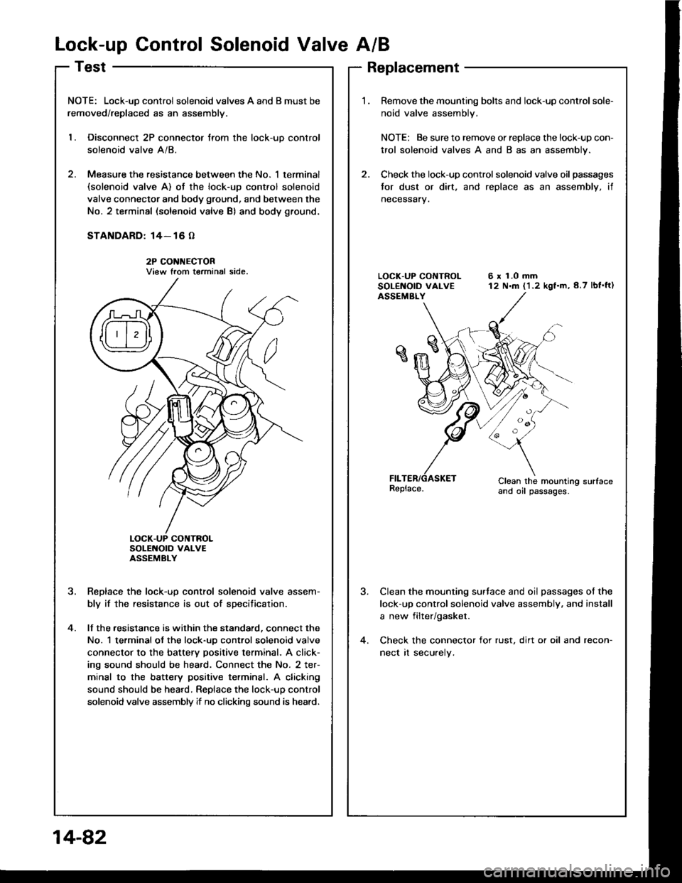
Lock-up Control Solenoid Valve A/B
NOTE: Lock-uD control solenoid valves A and B must be
removed/replaced as an assemblv.
l. Disconnect 2P connector trom the lock-uo control
solenoid valve A/8.
2. Measure the resistance between the No. 1 terminal(solenoid valve A) ot the lock-up cont.ol solenoid
valve connector and body ground, and between the
No. 2 terminal (solenoid valve B) and body ground.
STANDARD: 14- 16 O
2P CONI{ECTORView trom terminal side.
SoLENOTO VAI-VEASSEMBLY
Reolace the lock-uo control solenoid valve assem-
bly if the resistance is out of specitication.
lf the .esistance is within the standard, connect the
No. 1 terminal ot the lock-uo control solenoid valve
connector to the battery positive terminal. A click-
ing sound should be heard. Connect the No. 2 ter-
minal to the battery positive terminsl. A clicking
sound should be heard. Replace the lock-up control
solenoid valve assembly if no clicking sound is heard.
?
4.
Replacement
Remove the mounting bolts and lock-up control sole-
noid valve assembly.
NOTE: Be sure to remove or replace the lock-up con-
trol solenoid valves A and B as an assembly.
Check the lock-up control solenoid valve oil passages
tor dust or dirt. and replace as an assembly, if
neceSsary.
6 x 1.0 mm12 N.m (1.2 kgf.m,8.7 lbf'ft)
Clean the mounting sudaceand oil passages.
Clean the mounting surtace and oil passages of the
lock-up control solenoid valve assembly. and install
a new filter/gasket.
Check the connector for rust, dirt or oil and recon-
nect rt securely.
14-82
Page 475 of 1413
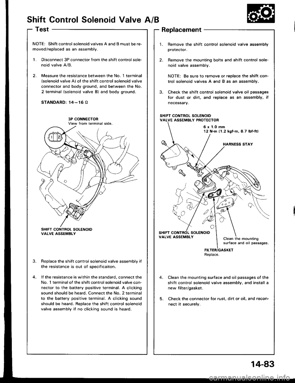
Shift Control Solenoid ValveA/B
Test
NOTE: Shift controlsolenoid valves A and B must be re-
moved/replaced as an assembly.
1.Disconnect 3P connector from the shitt control sole-
noid valve A/8.
Measure the resistance between the No. 1 terminal(solenoid valve A) of the shift control solenoid valve
connecto. and body ground, and between the No.
2 terminal (solenoid valve B) and body ground.
STANDARD: 14- 16 O
SHIFT CONTROL SOLENOIOVALVE ASSEMBLY
Replace the shift control solenoid valve assembly if
the resistance is out oI sDecificaiton.
lf the resistance is within the standard, connect the
No. 1 terminalof the shift controlsolenoid valve con-
nector to the battery positive terminal. A clicking
sound should be heard. Connect the No. 2 terminal
to the battery positive terminal. A clicking sound
should be heard. Replace the shift control solenoid
valve assembly if no clicking sound is heard.
3.
1.Remove the shift control solenoid vaive assembly
protector.
Remove the mounting bolts and shift control sole-
noid valve assembly.
NOTE: Be sure to remove or replace the shitt con-
trol solenoid valves A and B as an assembly.
Check the shitt control solenoid valve oil passages
for dust or dirt, and replace as an assembly, it
necessary.
Clean the mounting surface and oil passages of the
shitt control solenoid valve assembly, and install a
new filter/gasket.
Check the connector for rust, dirt or oil, and recon-
nect it securely.
6 x 1.0 mm12 N'm (1.2 kgl.m,4.7 lbl.ftl
VALVE ASS€MBLYClean the mountingsurface and oil passages.
Replace.
14-83
Page 482 of 1413
![HONDA INTEGRA 1994 4.G Repair Manual Road Test
NOTE: Warm up the engine to operating temperature (the cooling fan comes on).
1 Apply parking brake and block th€ wheels. Start the engine, them move the selector lever to E] position whil HONDA INTEGRA 1994 4.G Repair Manual Road Test
NOTE: Warm up the engine to operating temperature (the cooling fan comes on).
1 Apply parking brake and block th€ wheels. Start the engine, them move the selector lever to E] position whil](/img/13/6067/w960_6067-481.png)
Road Test
NOTE: Warm up the engine to operating temperature (the cooling fan comes on).
1 Apply parking brake and block th€ wheels. Start the engine, them move the selector lever to E] position whiledepressing the brake pedal. Depress the accelerator pedal, and release it suddenly. The engine should not stall,
2. Repeat same test in @ position.
3. Shift the selecto. lever to E position, and chock that the shift points occur at approximate speeds shown. Alsocheck fof abnormal noise and clutch slippage.
NOTE: Throttle position sensor voltage fepresents the throttle opening.
- 1 . Connect the Test Harness between the ECM and connector (see section 1 1).-2. Setthe digital multimeter to check voltage between D1 1{+)terminal and D22 { - ) terminal for the throttle Dosi-tion sensor.
TESTHARI{ESSOTLAJ_PT3OlOA
DIGITAL MULTIMETERCommarcially avsilablo o.KS-AHM-32-OO3
011 {+oooooooooooooooooooooooooooooooooooooooooooooooooooooooooooooooooooooooooooo
14-90
Page 557 of 1413
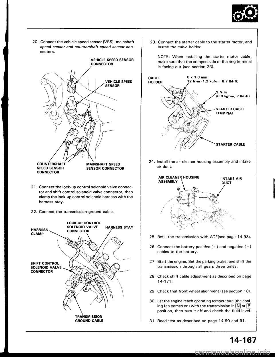
20. Connect the vehicle speed sensor (VSS), mainshatt
speed sensor and counterchalt speed sensor con
nectors.
VEHICLE SPEED SEiISORCONNECTOR
21. Connect the lock-uD control solenoid valve connec-
tor and shift control solenoid valve connector. then
clamp the lock-up control solenoid harness with the
harness stay.
22. Connect the transmission ground cable.
LOCK-UP CONTROLSOLENOID VALVE HARNESS STAY
23. Connect the starter cable to the starter motor, and
install the cable holder.
NOTE: When installing the starter motor cable,
make sure that the crimped side of the ring terminal
is facing out (see section 23).
CABLEHOLDER
6x 1.0 mm'12 N.m (1.2 kgf'm,8.7 lbt.tl)
24.
N.mlO.9 ksr.m, 7 tbr-rtt
STARTER CAELE
Install the air cleaner housing assembly and intake
arr oucl.
AIR CLEANER HOUSINGASSEMBLYINTAKE AIRDUCT
25.
26.
24.
29.
30.
Retill the transmission with ATF(see page '14-93).
Connect the battery positive ( + ) and negative ( - )
cables to the battery.
Start the engine. Set the parking brake, and shift the
transmission through all gears three times.
Check shitr cable adjustment as described on page
14-171 .
Check that front wheel alignment (see section 18).
Let the engine reach operating temperature (the cool-
ing tan comes on) with the transmission in S or @position, then turn it off and check the fluid level.
31. Road test as described on page 14-9o and 91.
14-167
Page 634 of 1413
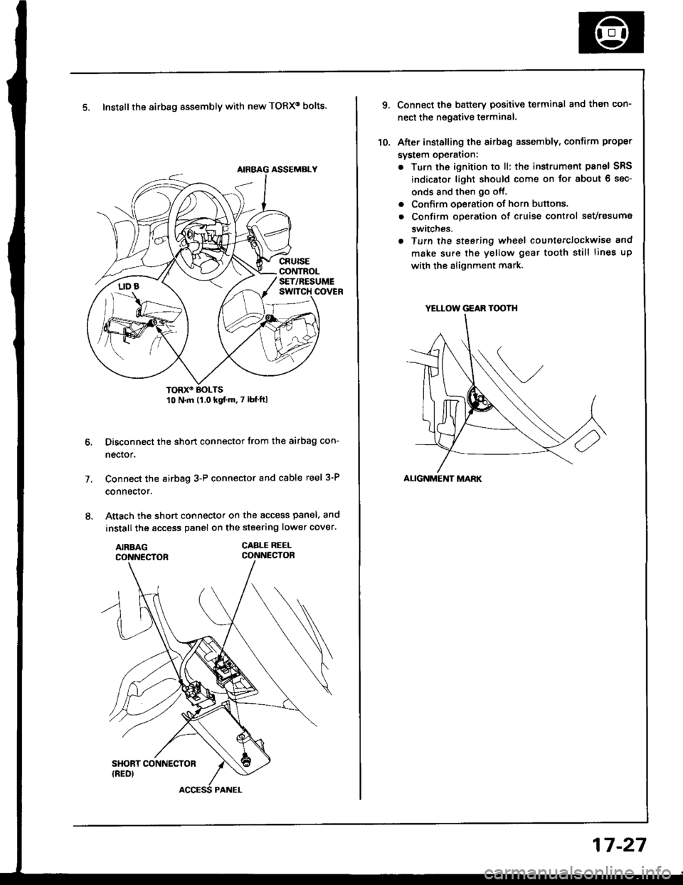
5. Install the airbag assembly with new TORXo bolts.
TORXO BOLTS10 N.m {1.0 kgf'm.7 lbf ftl
Disconnect the short connector trom the airbag con-
nector.
Connect the airbag 3-P connector and cable reel 3-P
connector.
Attach the short connector on the access panel. and
install the access panel on the steering lower cover.
CABLE REEI-CONNECTOR
7.
YELLOW GEAR TOOTH
ALIGNMENT MARK
10.
Connect the battery positive terminal and th€n con-
nect the nsgative terminal.
After installing the sirbag assembly, confirm proper
system opera(on:
. Turn the ignition to ll: the instrum€nt pan6l SRS
indicator light should come on for about 6 sec-
onds and then go off,
. Confirm operation of horn buttons.
. Confirm oDeration of cruise control sevresume
switches.
a Turn the steering wheel countetclockwise and
make su.e the yellow gear tooth still lines up
with the alignment mark.
17-27
Page 1048 of 1413
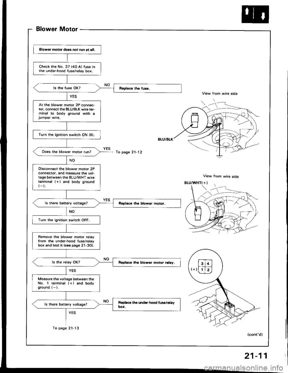
Blower Motor
View from wire side
View from wire side
Blowor motor doos noi iun at all.
check the No. 37 (4o A) fuse intho under-hood fuse/relay box.
At th€ blower motor 2P connec-tor, connect the BLU/8LK wirc ter-minal to body ground wath ajumpe. wire.
Turn the ignition switch ON (ll).
Does the blower motor run?
Disconnect the blower motor 2Pconnector, and measure the vol-tago between the ELU/wHT wireterminal {+} and body ground
{-}.
Turn the ignition switch OFF.
Remove the blower motor relavfrom the under-hood fuse/relavbox and test it {see page 21-3O}.
Roplaco tho blowor motor rolay.
Measure the voltage betwgen theNo. 1 terminal (+) and bodyground (- ).
To page 21-12
To page 2l-13
"uf"'\'
,)
(cont'dl
21-11