key HONDA INTEGRA 1994 4.G User Guide
[x] Cancel search | Manufacturer: HONDA, Model Year: 1994, Model line: INTEGRA, Model: HONDA INTEGRA 1994 4.GPages: 1413, PDF Size: 37.94 MB
Page 1111 of 1413
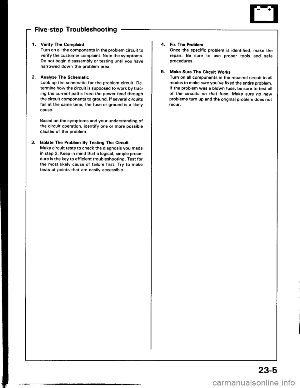
Five-step Troubleshooting
1. Verify The Complaint
Turn on all the components in the problem circuit to
verify the customer complaint. Note the symptoms.
Do not begin disassembly or testing until you have
narrowed down the Droblem area.
2. Analyze The Schomatic
Look up the schematic for the problem circuit. De-
termine how the circuit is supposed to work by trac-
ing the current paths from the power leed through
the circuit components to ground. It severalcircuits
fail at the same time, the luse or ground is a likely
cause.
Based on the symptoms and your understanding of
the circuit operation, identity one or more possible
causes of the Droblem.
3. lsolato The Problom By Testing The Circuit
Make circuit tests to check the diagnosis you made
in step 2. Keep in mind that a logical, simple proce-
dure is the key to etticient troubleshooting. Test for
the most likely cause of failure first. T.y to make
tests at points that are easilv accessible.
4. Fix The Problem
Once the specilic problem is identified, make therepair. Be sure to use proper tools and safeproceoures.
5. Mak6 Suro The Circuit Wolks
Turn on all components in the repaired circuit in allmodes to make sure you've fixed the entire problem.
It the problem was a blown Juse, be sure to test allof the circuits on thst tuse. Make sure no newproblems turn up and the original problem does not
recuf.
23-5
Page 1140 of 1413
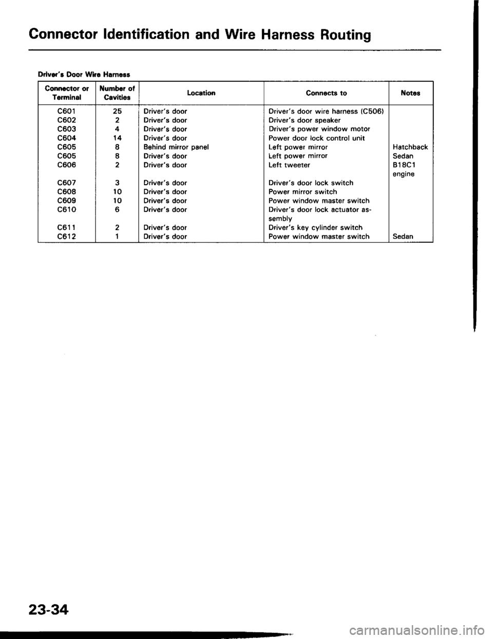
Connector ldentification and Wire Harness Routing
Drlvar's Door Wir6 Hamors
Connectot 01
Torminal
Number of
CavitlesLocationConnocts toNotos
c601
c602
c603
c604
c605
c605
c606
c607
c608
c609
c610
c61 1
c612
25
2
4
14
I
I
10
10
o
2
I
Driver's door
Driver's door
Driver's door
Driver's door
Behind mirror panel
Driver's door
Driver's door
Driver's door
Driv€r's door
Driver's door
Driver's door
Oriver's door
Driver's door
Oriver's door wire harness (C506)
Driver's door speaker
Driver's power window motor
Power door lock control unit
Left power mirror
Left power mirror
Lett tweeter
Driver's door lock switch
Power mirror switch
Power window master switch
D.iver's door lock actuator as-
sembly
Driver's key cylinder switch
Power window master switchSedan
Hatchback
Sedan
818C1
engrne
23-34
Page 1142 of 1413
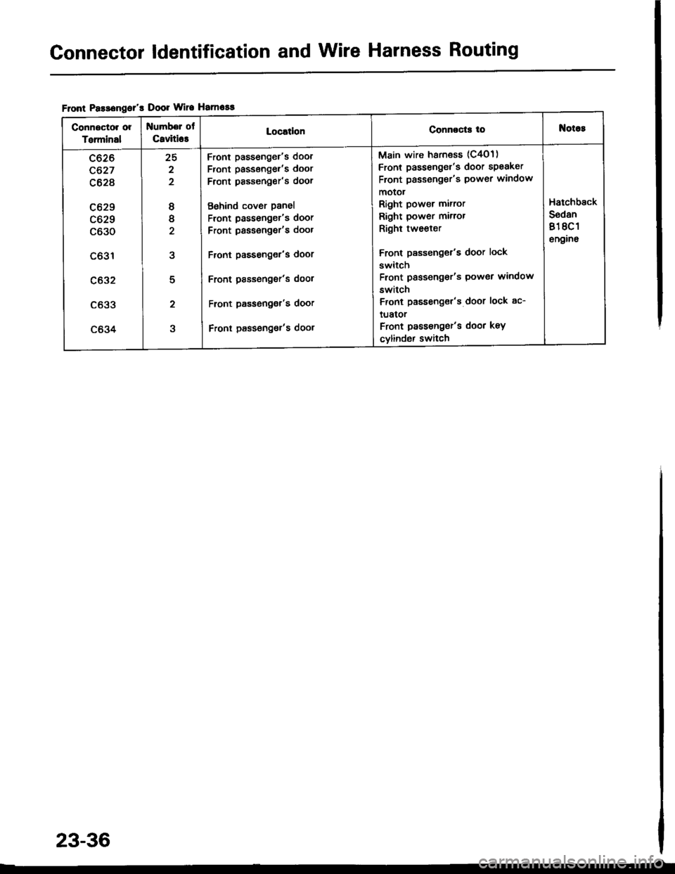
Connector ldentification and Wire Harness Routing
Flont Pasa€ngol's Door Wire Hamosg
Conngctor or
Talminal
Numbel of
C8viti63LocatlonConnocts toNot6s
c626
c627
c628
c629
c629
c630
c631
c632
c633
c634
25
2
2
8
tt
2
5
2
Front passenger's door
Front passsngel'�s door
Front pssseng€r's door
Behind cover panel
Front passenger's door
Front passengor's door
Front passenger's door
Front Passonger's dool
Front passeng€r's door
Front pass€ngot's door
Main wire harness (C4O1)
Front passenger's door speaker
Front passeng€r's power window
motot
Right power mirror
Right power mirror
Right tweeler
Front passenger's door lock
switch
Front passengor's Power window
switch
Front passenget's door lock ac-
tuator
Front passengor's door key
cylind6r switch
Hatchback
S6dan
818C 1
6n9ino
23-36
Page 1158 of 1413
Fuses
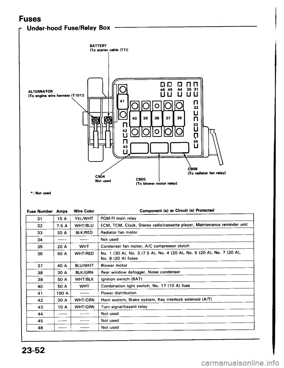
Under-hood Fuse/Relay Box
ALTERI{ATOR
fTo .ngino wlto hsrno$ {Tlolll
Not usod
r: l\lot u3.d
umborAmpsColor
nF n nn46 45 /t4 35 3l
UU U UU
n32
U
n
33
U
r:rg
U
n
42
U
n43
U
[To rldidor hn r.l.Yl
Componon! (sl 01 Clrcuit 13) Protoqtod
3115 AYEL/WHTPGM-Fl main relay
327.5 AWHT/BLUECM, TCM. Clock, Stereo radio/cassette plsyer, Maintenance reminder unit
a2204BLK/REDRadiator Jan motor
34Not used
35204WHTCondenser fan motor, A/C compressor clutch
50AWHT/REDNo. I {3O A), No. 3 (7.5 A). No. 4l2O Al, No 5 (2O A), No. 7 (2O A),
No. I (20 A) fuses
3740ABLU/lVHTBlower motor
3830ABLK/GRNRear window defogger, Noise condenser
?q50AWHT/BLKlgnition switch {BAT}
4050AWHTCombination light switch, No. 17 (1O Al fuse
41100 APower distribution
4220AWHT/GRNHorn system, Brake system, Key interlock solenoid (Aff)
4310 AWHT/GRNTurn signal/hazard.elay
44Not used
45Not used
46Not used
23-52
Page 1160 of 1413
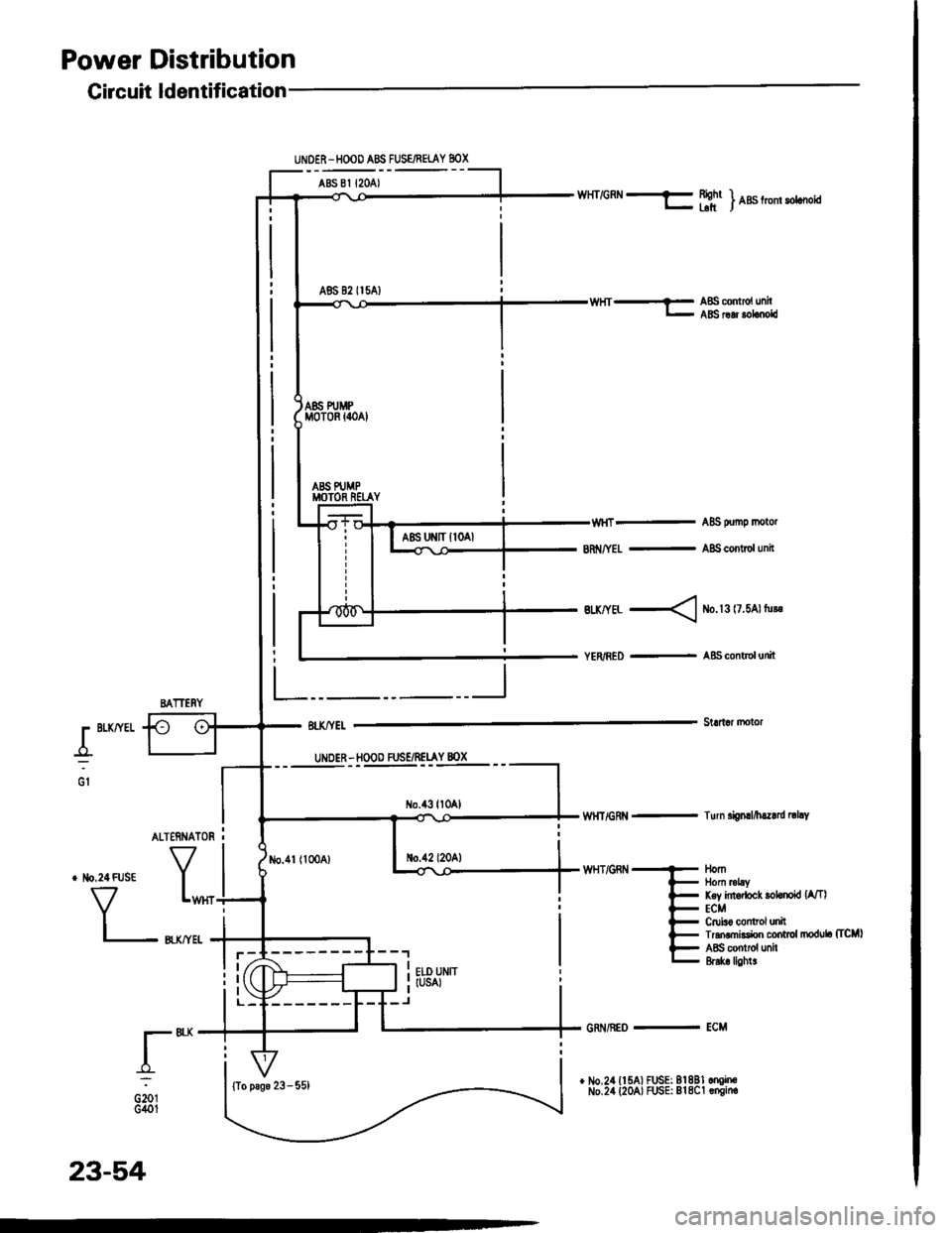
Power Distribution
L"I
.r"-
oiotG401
No.1l (100A)
UNOER-HOOD ABS FUSE/FEIAY 8OX
ABS 81 {2OA)
A86 82 II5AI
Gircuit ldentification
BATTERY
WHT/GRN f Bightr- blt) nas trom sotcooia
ABS oumo motor
8n /YEL - A8S contol unit
Btx/YEL < ib.l3 l7.5Al tu!.
YER/RED - A&S control unit
Stldar motorr BLKffEL
_o_:UNDER - HOOD FUSE/RELAY 8OX
No.43ll0Al
no.42 l20A)
wHT/GRt{ - Turn si0nrl/h.z.rd |thY
WHT/GRN
AL]ERNATOR I
tlomllom mLyKey intodock lohnokl {A/TlECMCruiso control unilTran.mksion control modub (TcMl
ABS contiol unh&6k lighl!
{To psge 23 - 55)
23-54
GRi{/REo - ECM
Page 1171 of 1413
![HONDA INTEGRA 1994 4.G User Guide S€d8n:
,.-*-{.4rr-*Powgr door lock contrclunitDrivors door lock actustorD ve/s door lock key cylind€l rwhchDdv6rs door lock switch
] Power window mrster switch)
Drivors soat bolt swhch
Brx,4/vH HONDA INTEGRA 1994 4.G User Guide S€d8n:
,.-*-{.4rr-*Powgr door lock contrclunitDrivors door lock actustorD ve/s door lock key cylind€l rwhchDdv6rs door lock switch
] Power window mrster switch)
Drivors soat bolt swhch
Brx,4/vH](/img/13/6067/w960_6067-1170.png)
S€d8n:
,.-*-{.4rr-*Powgr door lock contrclunitDrivor's door lock actustorD ve/s door lock key cylind€l rwhchDdv6r's door lock switch
] Power window mrster switch)
Drivor's soat bolt swhch
Brx,4/vHr --E
lfr] ff;nj *",r *n
Irunk latch swhchf l8iler lighting connectorLicoruo pl.to lightsRioht I .L€-ft J nnst rrn gnr
Riohr ) .... .L€-ft J ran||gnr
Power anlonna mototHigh mo0nt bt'k6lightRear window dotoggor
] oo "onuo,unn
t,*----l ,_^
=,-"*- - f ABs contrclunh
@:
@:
E'
Ddvo/s door wir€ hemoss
ABS sub - hafn6s.
G5o2
otoa
.:
G702
23-65
Page 1177 of 1413
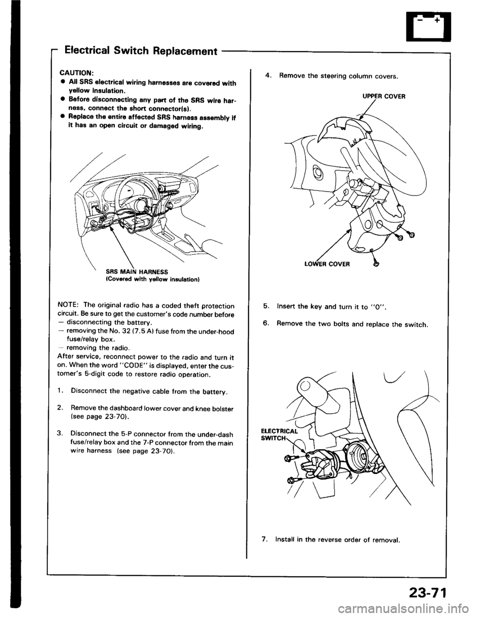
Electrical Switch Replacement
a All SRS €lectric8l wiring hamosses ar€ covorsd withyellow insulation,
a Befora disconnecting any pan of tho SRS wilo har-neas. connect the short connoctor(sl.a R6place the entire attect6d SFS harness assombly ifit has an opon circuit 01 damaged wiling.
NOTE: The original radio has a coded theft protection
circuit, Be sure to get the customer's code number before- disconnecting the battery.- removing the No. 32 (7.5 Al fuse from the under-hoodluse/relay box.- removang the radio.
After service, reconnect power to the radio and turn iton. When the word "CODE" is displayed, enter the cus-tomer's 5-digit code to restore radio ope.ation.
1. Disconnect the negative cable from the batery.
2. Remove the dashboard lower cover and knee bolster
{see page 23-70).
3. Disconnect the 5-P connector from the under-dashfuse/relay box and the 7-P connector from the mainwire harness (see page 23-70).
E
4. Remove the steering column covers.
Insert the key and turn it to ,,O',.
Remove the two bolts and replace the switch.
UPPER COVER
7. Install in the reve.se orde. of removat.
23-71
Page 1178 of 1413
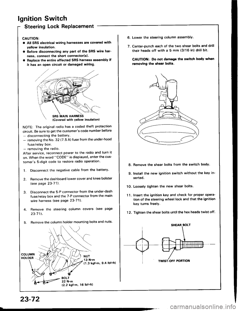
lgnition Switch
Steering Lock Replacement
CAUTION:
a All SRS electrical wiring harnesses ale covsred with
yellow insulation.
a Belore disconnecting any parl ot the SRS wir€ hal-
ness, connecl the short connector{s).
a Replace the entire alfected SRS harness a$6mbly il
it has an open circuit or damaged wiring.
NOTE: The original radio has a coded thett protection
circuit. Be sure to get the customer's code number betore
- disconnecting the batterY.
- removing the No. 32 (7.5 A) fuse from the under-hood
fuse/relay box.- removing the radio.
After service, reconnect power to the radio and turn it
on. When the word "CODE" is displayed, enter the cus-
tomer's 5-digit code to restore radio operation.
1. Disconnect the negative cable from the battery.
2. Remove the dashboald lower cover and knee bolster
(see page 23-7'l ).
3. Disconnect the 5-P connector from the under-dash
fuse/relay box and the 7-P connector trom the main
wire harness {see page 23-71).
4. Remove the steering column covers (see page
23-711.
5. Remove the column holder mounting bolts and nuts'
BOLT22 N.m
12.2 kgl'm.
NUT13 N.m(1.3 kgf.m, 9.4 lbl'ftl
23-72
16 tbt.ftl
6. Lower the steering column sssembly.
7. Center-Dunch each oJ the two shear bolts and drill
their heads off with a 5 mm {3/1 6 in) drill bit'
CAUTION: Do not dama96 tho switch body whon
r€movlng the shoar bol$.
Remove the shear bolts from the switch body.
Install the new ignition switch without the key in-
serted.
Loosely tighten the new shear bolts.
Insert the ignition key and check for proper opera-
tion of the steering wheel lock and that th€ ignition
key turns freely.
Tighten the shear bolts untilthe hex heads twist off.
8.
q
10.
11.
12.
Page 1183 of 1413
5. Check lor 8n op€n in the BLKMHT wire circuit be-
tween the staner and ignition switch, and con-
nectors.
6. Check the ignition switch (see page 23-70).
7, On cars with automatic transmission, check the A/Tgear position switch (neutral position switchl and
connector. On cars with manualtransmission, check
the staner cut relay, clutch interlock switch, and
connectors.
NOTE: Check the No. 39 (5O A) fuse in the under-hood
fuse/relay box for the starter cut relay.
Check tor Woar and Damago:
The starter should crank the engine smoothly and stead-
ily. lf th€ startsr engages, but cranks the engine errati-
cally, remove it. Inspect the starter, drive gear, and
flywheel ring gesr for damage.
a Check the drive gear overunning clutch for binding
or slipping when the armature is rotated with the drivegear held. Replace the gesrs if damaged.
Check Cranking Voltago 8nd Current Draw:
Cranking voltage should be no less than 8.O volts.
Current draw should be no more than 360 amperes.
lf cranking voltag€ is too low, or current draw too high,
check for:
a Fully charged battery
a Open circuit in starter armature commutatot segments
a Starter armature dragging
a Shoned armature winding
a Excessive drag in engine
Chack Cranking rpm:
Engine spsod during cranking should be above 1O0 rpm.
lf spe6d is too low, ch€ck for:
a Loose battsry or starter teminals
a Excessively worn starter brushes
a Open circuit in commutator segments
a Dirty or damaged helical spline or drive gear
a Defective drive gear overrunning clutch
Chock StErtor Disongagomoni:
Press the clutch pedal allth€ way in (M/T), turn the ioni-
tion switch to "lll" and rolease to "11".
The starter drive gear should disengage from the tlywheel
ring gear. When you rolease the key.
lf the drive gear hangs up on th€ flywheel ring gear, check
for:
a Solenoid plunger and switch malfunction
a Dirty drive gear assembly or damaged overrunning
clutch
23-77
Page 1244 of 1413
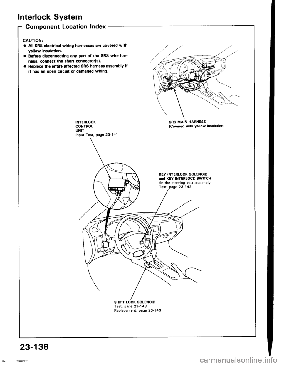
Interlock System
Component Location Index
All SRS electrical wiring harnass€s are covered with
yallow insulation.
Before disconnecting any part of the SRS wire har-
ness, connect the shon connector(sl.
Replace the entire affected SRS halness ass€mbly it
it has an open circuit or damaged wiring.
INTERLOCKCONTROLUNITfnput Test, page 23-141
SRS MAI[{ HARNESS
lcovorod with yellow insulstionl
SHIFT LOCK SOLENOIOTest, page 23- 143Repfacement, page 23-1 43
KEY INTERLOCK SOLENOIDsnd KEY INTERLOCK SWITCH(ln the steering lock assembly)Test, page 23-142
23-138