light HONDA INTEGRA 1994 4.G User Guide
[x] Cancel search | Manufacturer: HONDA, Model Year: 1994, Model line: INTEGRA, Model: HONDA INTEGRA 1994 4.GPages: 1413, PDF Size: 37.94 MB
Page 140 of 1413
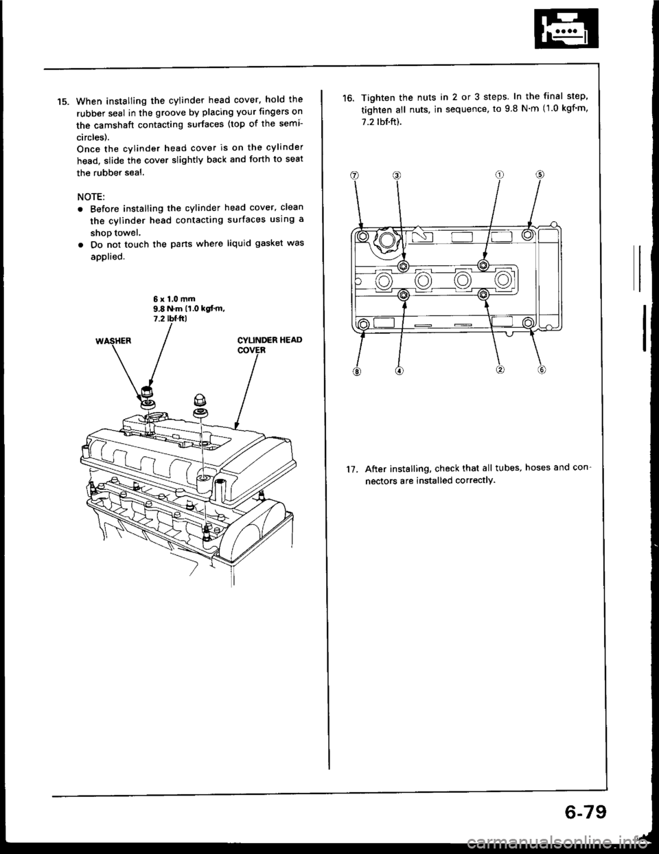
When installing the cylinder head cover. hold the
rubber seal in the groove by placing your fingers on
the camshaft contacting surfaces (top of the semi-
circles).
Once the cylinder head cover is on the cylinder
head, slide the cover slightly back and forth to seat
the rubber seal.
NOTE:
Before installing the cylinder head cover, clean
the cylinder head contacting surfaces using a
shop towel.
Do not touch the pans where liquid gasket was
applied.
6x1.0mm9,8 N.m 11.0 kgt'm,7.2 tffirl
Tighten the nuts in 2 or 3 steps. In the final step'
tighten all nuts, in sequence, to 9.8 N'm (1.0 kgf'm,
7.2 tbf.ft).
After installing, check that all tubes, hoses and con-
nectors are installed correctly.
17.
6-79
Page 154 of 1413
Cylinder Block
Inspection (cont'dl
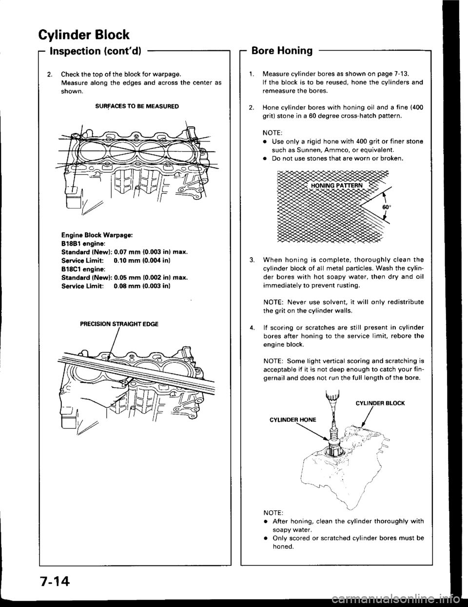
2.Check the top of the block for warpage.
Measure along the edges and across the center as
snown.
SURFACES TO BE MEASURED
Engine Block Warpsgc:
81881 ongine:
Standard lNewl: 0.07 mm {0.003 inl max.
Service Limil: 0.10 mm {0.00,1inl
B18Cl engine:
Standard (New): 0.05 mm 10.002 inl max.
Service Limit 0.08 mm {0.003 inl
Measure cylinder bores as shown on page 7-13.
lf the block is to be reused, hone the cylinders and
remeasure the bores.
Hone cylinder bores with honing oil and a fine (400
grit) stone in a 60 degree cross-hatch pattern.
NOTE:
. Use only a rigid hone with 400 grit or finer stone
such as Sunnen, Ammco, or equivalent.
a Do not use stones that are worn or broken.
When honing is complete, thoroughly clean the
cylinder block of all metal panicles. Wash the cylin-
der bores with hot soapy water, then dry and oil
immediately to prevent rusting.
NOTE: Never use solvent, it will only redistribute
the grit on the cylinder walls.
lf scoring or scralches are still present in cylinder
bores after honing to the service limit, rebore the
engine block.
NOTEr Some light venical scoring and scratching is
acceptable if it is not deep enough to catch your fin-
gernail and does not run the full length of the bore.
CYLINDER HONE
. After honing, clean the cylinder thoroughly with
soapy water.
. Only scored or scratched cylinder bores must be
noneo.
7-14
Page 165 of 1413
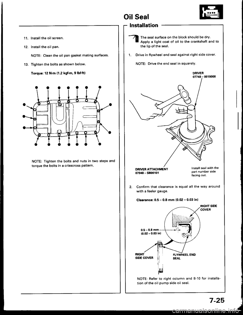
11.lnstallthe oil screen.
Installthe oil pan.
NOTE: Clean the oil pan gasket mating surfaces.
Tighten the bolts as shown below.
Torque: 12 N.m {1.2 kgf.m, 9 lbf'ft)
NOTE: Tighten the bolts and nuts in two steps and
toroue the bolts in a crisscross pattern
1'�I
Oil Seal
lnstallation
The seal surface on the block should be dry.
Apply a light cost of oil to the crankshaft and to
the liD of the seal.
Drive in flywheel end seal against right side cover.
NOTE: Drive the end seal in squarely.
DRIVER07t,49 - (xll(xtoo
2. Confirm that clearance is equal all the way around
with a fe€ler gauge.
Cler.6nce: 0.5 - 0.8 mm (0.02 - 0.03 inl
RIGHT SIDECOVER
NOTE: Reter to right column and 8-10 lor installa-
tion of the oil pump side oil seal.
lnstall sealwith thepart number sidetacing out.
7-25
Page 166 of 1413
Installation (engine removal not
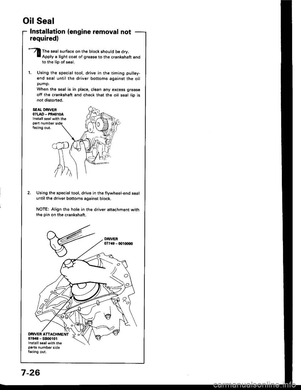
S€AL DRIVEB07LAD - PRimroAlnstallse6lwith tho
Pan numbertacing out.
Using the special tool, drive in the flywheel-end seal
until the driver bottoms against block.
NOTE: Align the hole in the drivsr attachment withthe Din on the crankshaft.
Oil Seal
required)
The seal surface on the block should b€ dry.Apply a light coat of grease to the crankshaft andto the lio of seal.
Using the special tool, drive in the timing pullsy-
end seal until the driver bottoms against the oilpump.
When the seal is in place, clean any excess grease
off lhe crankshaft and check that the oil seal tiD isnot distoned.
7-26
Page 172 of 1413
Englne Oil
Replacement {cont'd)
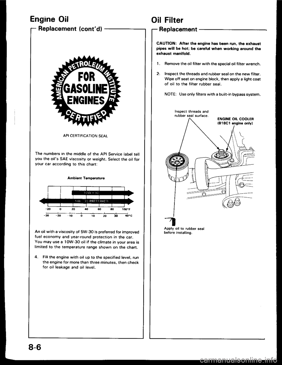
API CERTIFICATION SEAL
The numbers in the middle of the API Service label tellyou the oil's SAE viscosity or weight. Select the oil foryour car according to this chart:
Ambient TomDo?aturo
An oil with a viscosity of 5W-3O is preferred for improvedfuel economy and year-round protection in the car.You may use a l OW-3O oil it the climate in your area islimited to the tempe.ature range shown on the chart.
4. Fillthe engine with oil up to the specified level, .un
the engine for more than three minutes. then checklor oil leakage and oil level.
ElrclltEs
Oil Filter
Replacement
CAUTION: Aftar the ongine has boan run. tho oxhaustpipos will bo hot; b€ caretul when wo.king around tho
erhaust manitold,
Remove the oil tilter with the special oil filter wrench.
Inspect the threads and rubbe. sealon the new lilter.
Wipe off seat on engine block. then apply a light coat
of oil to the tilter rubber seal,
NOTE: Use only filrers with a built-in bypass system.
Inspect threads andrubber seal surface-
Apply oil to rubber sealbetore anstalling.
ENGINE OIL COOLER(8'l8Cl ongino onlyl
8-6
Page 174 of 1413
Oil Pressure
Testing
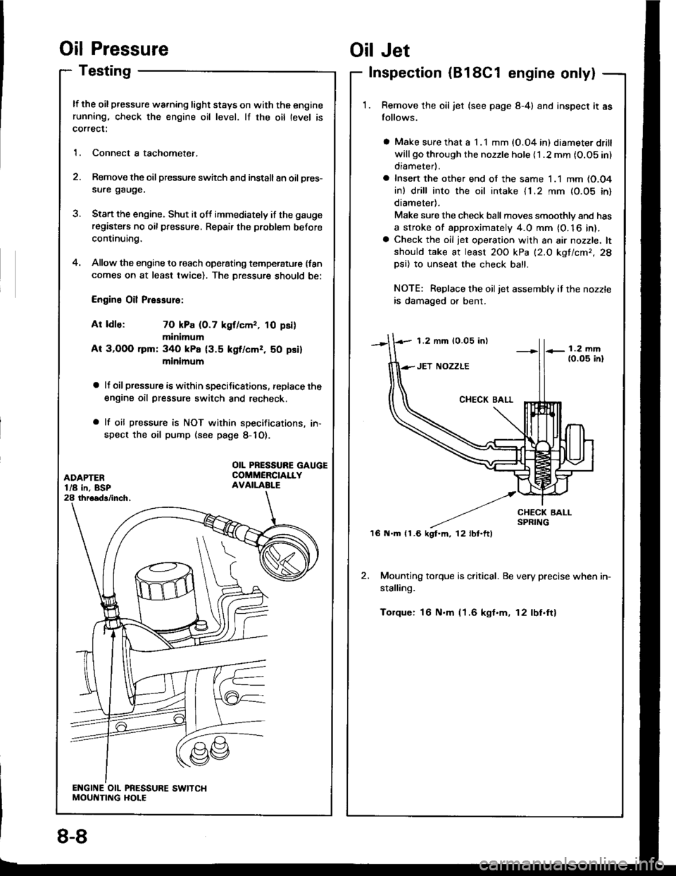
lf the oil pressure warning light stays on with the enginerunning, check the engine oil level. lf the oil level is
correct:
1. Connect a tachometer.
2. Remove the oil pressure switch and install an oil pres-
sure gauge.
3. Stan the engine. Shut it off immediately if the gauge
registers no oil pressure. Repair the problem before
continuing.
4. Allow the engine to reach operating temperatu,e {fancomes on at least twice). The Dressure should be:
Engine Oil Pressure:
At ldle: 70 kPa (0.7 kgf/cmr, 10 psi)
minimum
At 3,OOO lpm: 340 kPa {3.5 kgf/cmz, 50 psi}
minimum
a lJ oil pressure is within speciJications, replace the
engine oil pressure switch and recheck.
a lf oil pressure is NOT within specifications, in-
spect the oil pump (see page 8-1O).
1.2 mm 10.05 in)
'16 N.m (1.6 kgt.m, l2lbt.ftl
Oil Jet
Inspection (B18C1 engine only|
Remove the oil jet (see page 8-4) and inspect it as
follows.
a Make sure that a I .l mm (O.04 in) diameter drill
will go through the nozzle hole {1 .2 mm {O.OS in)
diameterl.
a Insert the other end of the same 1.1 mm (O.O4
in) drill into the oil intake {1.2 rnm {0.05 in}
diameter).
Make sure the check ball moves smoothlv and has
a stroke of approximately 4.0 mm {O. 16 in).a Check the oil jet operation with an air nozzle. lt
should take at least 2OO kPa (2.O kgf/cmr,28
Dsi) 10 unseat the check ball.
NOTE: Replace the oiljet assembly if the nozzle
is damaged or bent.
2. Mounting torque is critical. Be very precise when in-
stalling.
Torque: 16 N.m (1.6 kgt.m, 12lbf.ftl
OIL PRESSURE GAUGECOMMERCIALLYAVAILABI.E
8-8
Page 177 of 1413
t5.Check the housing-to-outer rotor radial clearance.
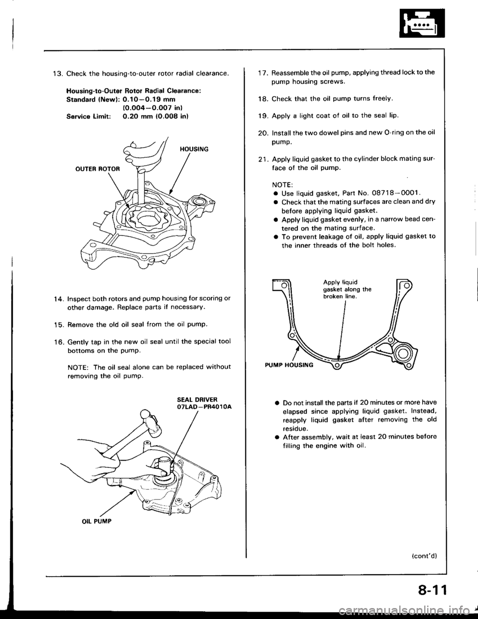
Housing-to-Outer Rotol Radial Clearance:
Standard {Newl: O.1O -O.19 mm(O.oO4-O.OO7 in)
Servic€ Limit: O.2O mm {O,OO8 in)
Inspect both rotors and pump housing for scoring or
other damage. Replace parts il necessary.
Remove the old oil seal trom the oil pump.
Gently tap in the new oil seal until the special tool
bottoms on the PumP.
NOTE: The oil seal alone can be replaced without
removing the oil pump.
14.
15.
to-
OIL PUMP
8-11
1'lReassemble the oil pump, applying thread lockto the
pump housing screws.
Check that the oil pump turns freely.
Apply a light coat of oil to the seal lip.
Install the two dowel pins and new O-ring on the oil
pump.
Apply liquid gasket to the cylinder block mating sur-
face of the oil pump.
NOTE:
. Use liquid gasket, Part No. 08718-OOO1.
a Check that the mating surfaces are clean and dry
betore applying liquid gasket.
a Apply liquid gasket evenly, in a narrow bead cen-
tered on the mating surface.
a To prevent leakage of oil, apply liquid gasket to
the inner threads ot the bolt holes.
Do not install the parts if 20 minutes or more have
elapsed since applying liquid gasket. Instead.
reapply liquid gasket aftet removing the old
restclue.
After assembly, wait at least 20 minutes before
filling the engine with oil.
(cont'd)
18.
19.
20.
Page 204 of 1413
System Description
Electrical Connections
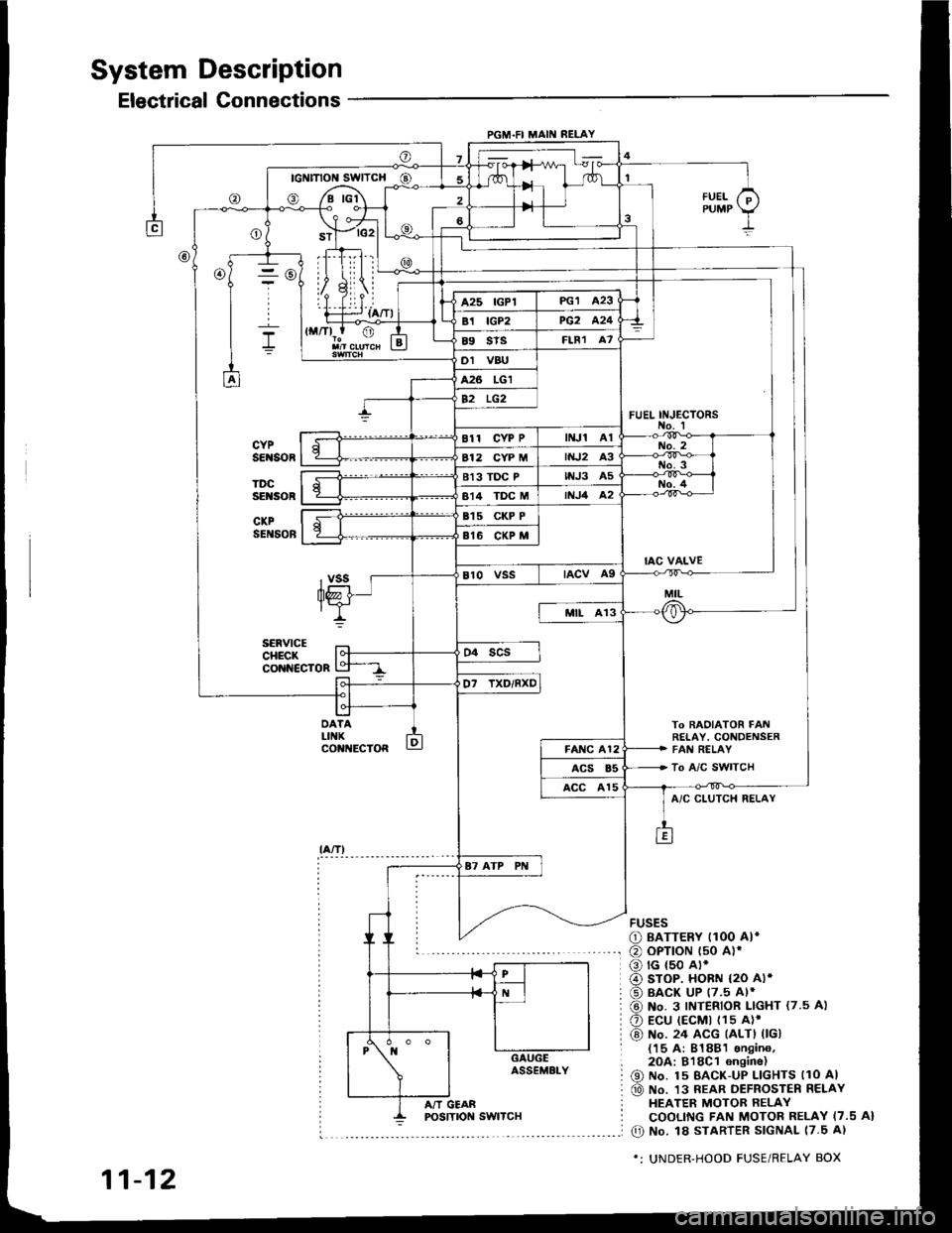
PGM.FI MAII{ RELAY
- rc2l L
IllLii |
ril.i--r {a/Tl
To BAOIATOR FAt!RETAY, CONDENSERFAI{ RELAY
To A/C SWITCH
FUEL INJ€CTORS
@
DATALIIIKco t{EcToR
fUELPUMP
A/C CLUTCH RELAY
FUSES
O BATTERY I1OO AI*
@ oPTroN t50 alr
o rG {50 A).
@ sroP. HoBN {2O Al*
@ BACK UP (7.5 Al*
@ No. 3 INTERIOR LIGHT {7.5 A)
O Ecu (EcMt (1s A)'
@) No. 24 ACG (ALTI 0Gl{15 A: 81881 sngin6,2OA:818C1 6n9ine)
@ No. 15 BAcK-uP LlcHTs llo Al
@ No. 13 REAR DEFROSTER RELAYHEATER MOTOR RELAYCOOLING FAN MOTOR RELAY I7.5 A}
O No. l8 STARTER SIGNAL 17.5 A)
*: UNDER-HOOD FUSE/RELAY BOX
11-12
A/T GEAR
Page 210 of 1413
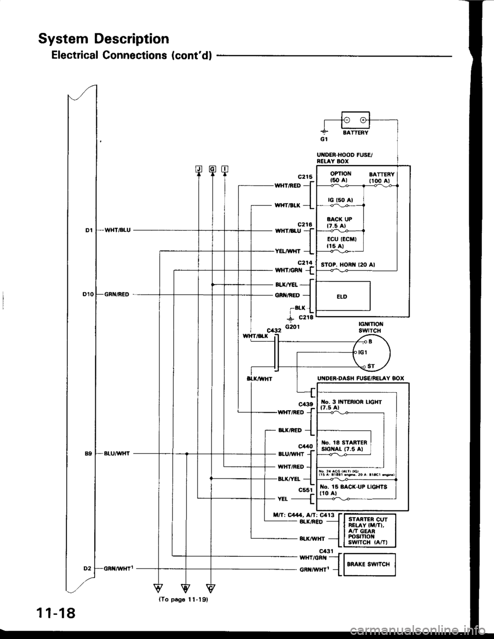
System Description
Electrical Connections (cont'dl
160 Al fioo Al
sToP. HORI{ t20 Al
wnrneo
J
,*rr"a* -l
c216wHr/8ru TIYEL/WHT --L
c214wHvem {
auryet{
oR nED -l
-alx {
I "rti'f_ c218
G20r
wxrneo {
"a*,"ao {
c44t)*utwxr
{wHriRED --l
or-rrv:r- {c551-{
nft C4. Af,: Ca13 f- 8rr(/nED -l
- surwxr -{
I{o. 3 lttTERlOR LIGHT
l|5^.llll.n'i'20r!|.c1q*,
o. la STARTERstGI{At- t7.5 Al
No. 15 8ACK-UP LIGHISt10 al
{To ptg€ 11-19,
1 1-18
el3t Fw{T/GRr{ _-]
cR ^i|Hrl 1
Page 226 of 1413
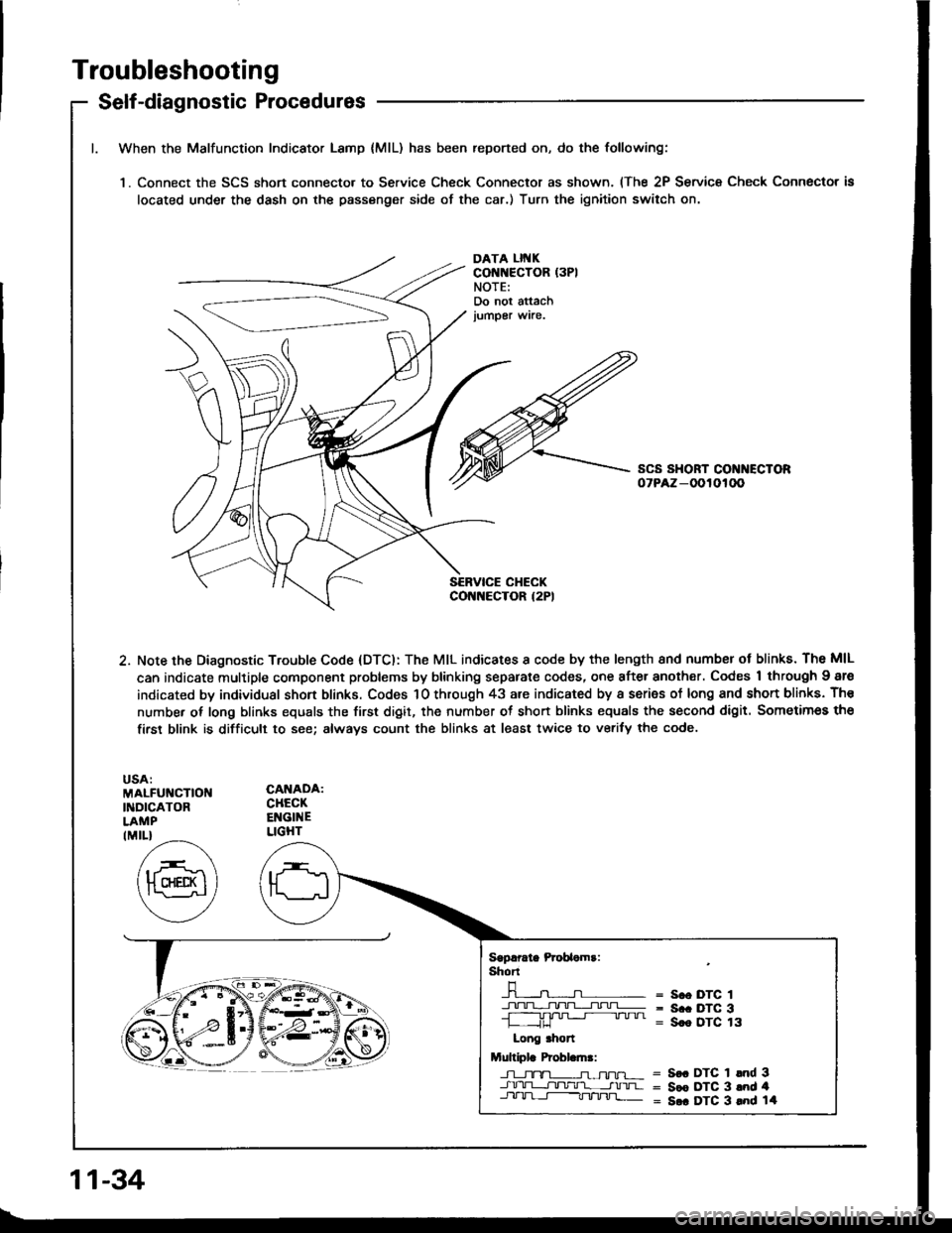
Troubleshooting
Self-diagnostic Procedures
When the Malfunction Indicator Lamp {MlL) has been reported on, do the following:
'1. Connect the SCS short connecto. to Service Check Connector as shown. (The 2P Service Check Connector is
located under the dash on the passenger side of the car.) Turn the ignition switch on.
DATA LII{KCONNECTOR (3PI
NOTE:Do not attachjumper wire.
2. Note the Diagnostic Trouble Code (DTC): The MIL indicates I code by the length 8nd numbsr ot blinks. The MIL
can indicate multiple component problems by blinking separate codes, one after another. Codes 1 through Igre
indicated by individual shon blinks. Codes 1O through 43 are indicated by a series of long and shon blinks. Th€
number of long blinks equals the first digit, the number ot short blinks equals the second digit. Sometimes the
firsr blink is difficult to see; always count the blinks at least twice to verify the code.
MALFUNCTIOI{INDICATORLAMP
CANADA:CHECKENGINELIGHTIMIL}
Sgprrate Prcbaomr:shT
-n-----n- =n- = s.o DTc 1
+!+1].TL;I!!=- = s.. Drc 3-L ,JU '" " " = Sce DTC 13
Long .hon
Multiplr Probl.ln.:
J-l_tx-TL-n-ffu-r- = S€. DTC 1 lnd 3-J.rrU-L-r]tltlr'l- __-tnrua = Sce DTC 3 and 4Jll-lrl-t-----Tt/'tnj]_ = S.. DTC 3 lnd 14
11-34