light HONDA INTEGRA 1994 4.G Service Manual
[x] Cancel search | Manufacturer: HONDA, Model Year: 1994, Model line: INTEGRA, Model: HONDA INTEGRA 1994 4.GPages: 1413, PDF Size: 37.94 MB
Page 411 of 1413
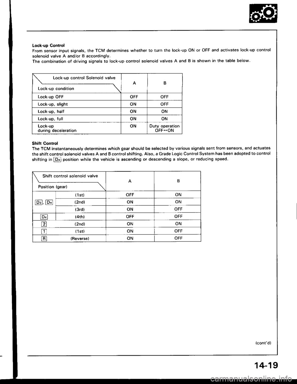
Lock-up Control
From sensor input signals, the TCM determines whether to turn the lock-up
solenoid valve A and/or B accordingly.
The combination of driving siqnals to lock-up control solenoid valves A and
ON or OFF and activates lock-up control
B is shown in the table below.
Lock-up control Solenoid valve
B
Lock-up condition \
Lock-up OFFOFFOFF
Lock-up, slightONOFF
Lock-up. haltONON
Lock-up. fullONON
Lock-upduring decelerationONDuty operationOFF-ON
Shifl Conrrol
The TCM instantaneously determines which gear should be selected by various signals sent trom sensors. and actuates
the shift control solenoid valves A and B control shitting. Also. a Grade Logic Control System has been adopted to control
shifting in E] position while the vehicle is ascending or descending a slope, or reducing speed.
Shift control solenoid valve
t"*b" ,t"-l
------\B
E,E
('l st)OFFON
(2ndlONON
(3rd)ONOFF
E(4th)OFFOFF
a(2nd)ONON
tr (lst)ONOFF
l-Rl {Reverse)ONOFF
(cont'd)
14-19
Page 431 of 1413
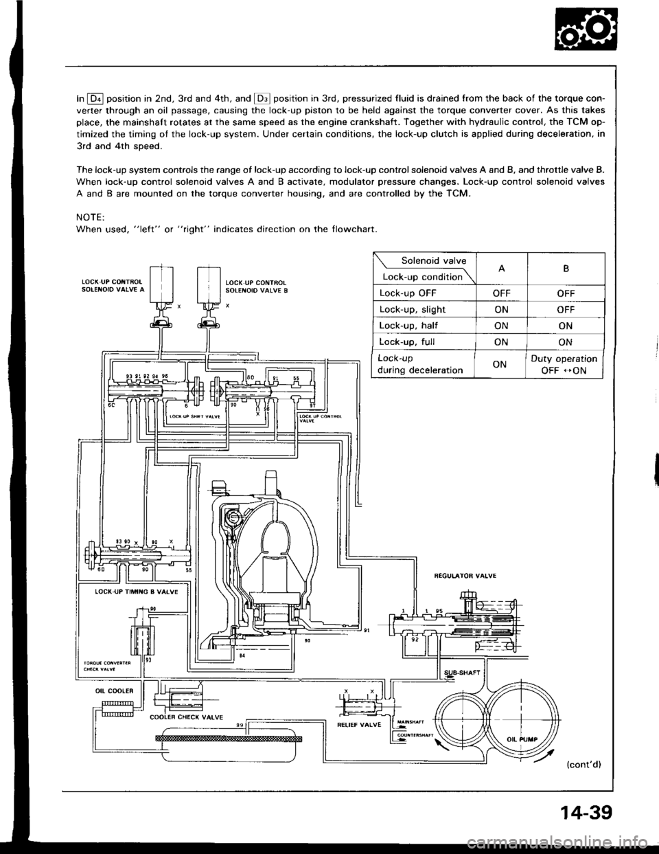
In E position in 2nd, 3rd and 4th, and @ position in 3rd, pressurized fluid is drained from the back of the torque con-
verter through an oil passage, causing the lock-up piston to be held against the torque converter cover. As this takes
place, the mainshaft rotates at the same speed as the engine crankshaft. Together with hydraulic control, the TCM op-
timized the timing ot the lock-up system. Under certain conditions, the lock-up clutch is applied during deceleration, in
3rd and 4th sDeed.
The lock-up system controls the range of lock-up according to lock-up control solenoid valves A and B, and throttle valve B.
When lock-up control solenoid valves A and B activate. modulator pressure changes. Lock-up control solenoid valves
A and B are mounted on the torque converter housing, and are controlled by the TCM.
NOTE:
When used, "left" or " tight" indicates direction on the tlowchart.
LOCK IJP COIITBOL
Solenoid valve
L""f."p "."aiti""\B
Lock-up OFFOFFOFF
Lock-up, slightONOFF
Lock-up, halfONON
Lock-up. fullONON
Lock-up
during decelerationONDuty operation
OFF -ON
LOCI( UP TIMII{G B VAIVE
{cont'd)
ott coot€R
14-39
Page 433 of 1413
{l
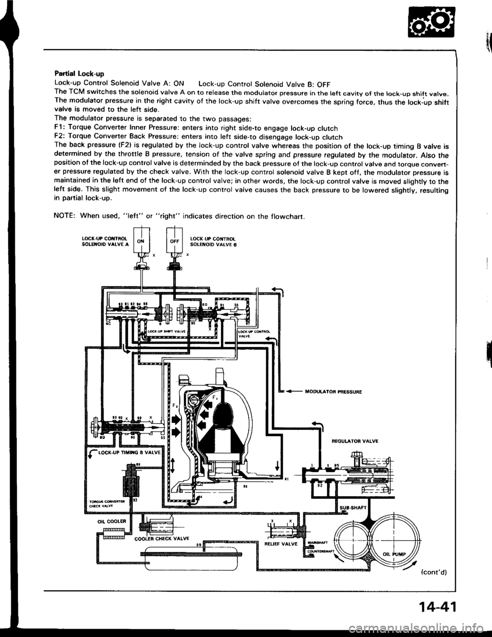
Partial Lock-up
Lock-up Control Solenoid Valve A: ON Lock-up Control Solenoid Valve B: OFFThe TCM switches the solenoid valve A on to release the modulator pressure in the left cavity ol the lock-up shift vatve.The modulator pressure in the right cavity of the lock-up shift valve overcomes the spring force, thus the lockiup shifivalve is moved to the left side.
The modulator pressure is separated to the two passages:
F1: Torque Converter Inner Pressure: enters into right side-to engage lock-up clutchF2: Torque Convener Back Pressure: enters into left side-to disenqage lock-up clutchThe back pressure (F2) is regulated by the lock-up control valve whereas the position of the lock-up timing B valve isdetermined by the throttle B pressure, tension of the valve spring and pressure regulated by the modulator, Also theposition of the lock-up control valve is determinded by the back pressure of the lock-up control valve and torque conven-er pressure regulated by the check valve. With the lock-up cont.ol solenoid valve B kept oft, the modulator p.essu.e ismaintained in the left end of the lock-up control valve; in other words, the lock-up control valve is moved slightly to theleft side. This slight movement of the lock-up conlrol valve causes the back pressure to be lowered slightly. resultingin panial lock-up.
NOTE: When used. "left" or "right" indicates direction on the flowchart.
LOCK.UP COIIIROLSO!ENO|o VALVE ALOCK UP COIITROISOTENOID VALVE B
<- MODUI.AIOi PAESSUFE
7 l.ont'al
LOCK-UP IIMII{G B VATV€
otl coolEn
14-41
Page 436 of 1413
Description
Lock-up System (cont'dl
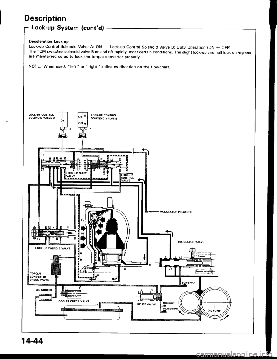
Dacslsration Lock-uD
Lock-up control solenoid valve A: oN Lock-up control solenoid valve B: Duty operation {oN - oFFlThe TCM switches solenoid valve B on and off rapidly under certain conditions. The slight lock-up and half lock-up regionsare maintained so as to lock the torque converter properly.
NOTE; When used, "left" or "right" indjcates direction on the flowcnarr.
LOCK-I.P COt{lFOtloc(,uP cot{TRoLSOIENOID VATVE B
LOCI(,UP TtMt G B VAIVE
14-44i
Page 440 of 1413
![HONDA INTEGRA 1994 4.G Service Manual Troubleshooting Procedures
when the TcM senses an abnormality in the input or output systems. the E]indicator light in the gaugo assembly willblink.
when the service check Connector {located under the HONDA INTEGRA 1994 4.G Service Manual Troubleshooting Procedures
when the TcM senses an abnormality in the input or output systems. the E]indicator light in the gaugo assembly willblink.
when the service check Connector {located under the](/img/13/6067/w960_6067-439.png)
Troubleshooting Procedures
when the TcM senses an abnormality in the input or output systems. the E]indicator light in the gaugo assembly willblink.
when the service check Connector {located under the dash on the passenger side} is connected with the specaat toolas shown, the E] indicator light will blink the Diagnostic Trouble iode {DTCI when the ignition switch is turned on.
When the lDil indicator light has been reported on, connect the service check connector with the special tool.Then turn on the ignition switch and observe the @ indicator light.
GAUGE ASSEMSLY
)'t
DAI'A LI]TKcor{r{EcToR (3P)NOTE:Do not atlachjumpe. wire.
Sc. DTCI
So. DTC2
S.. DTC14
scs sHoRT CO[{]{ECTORoTPAZ-OOl0too
codes 1 through I are indicated by individual short blinks, codes 1o through 1 5 are indicated by a series of tong andshon blinks. one long blink equals l0 short blinks. Add the long and short blinks together to dete;mins the cod€. Aft6rdetermining the code, refer to the erectricar system symptom-to-component chart on pages 14-5o and 51.
ahon
f"l
some PGM-FI problems will also make the @ indicator light come on. After repairing the pGM-Fr system, disconnectthe BACK UP tuse (7.5 Al in the under-hood fuse/relay box tor more than 1o seconds to reset the TcM memorv.
NOTE:
a PGM-FI svstem
The PGM-FI system on this model is a sequential multipon fuel iniection svstem.' Disconnecting the BACK UP tuse also cancels the radio anti-theft code, preset stations and the clock setting. G6tthe customer's code numbe. and make note of the radio presets befote temoving the fuse so you can reset them.
14-48
Page 442 of 1413
![HONDA INTEGRA 1994 4.G Service Manual Symptom-to-Component Chart
Electrical System
Number of @indicator light
blinks while
Service Check
Connector is
connected with
the special tool.
@] indicaror
lightPossible CauseSymptomRefer to
page
Bl HONDA INTEGRA 1994 4.G Service Manual Symptom-to-Component Chart
Electrical System
Number of @indicator light
blinks while
Service Check
Connector is
connected with
the special tool.
@] indicaror
lightPossible CauseSymptomRefer to
page
Bl](/img/13/6067/w960_6067-441.png)
Symptom-to-Component Chart
Electrical System
Number of @indicator light
blinks while
Service Check
Connector is
connected with
the special tool.
@] indicaror
lightPossible CauseSymptomRefer to
page
BlinksDisconnected lock-up control solenoidvalve A connector
Short or open in lock-up control sole-noid valve A wire
Faulty lock-up control solenoid valve A
Lock-up clutch does not
engage.
Lock-up clutch does not
disengage.
Unstable idle speed.
14-52
BlinksDisconnected lock-up control solenoidvalve B connector
Short or open in lock-up control sole-noid valve B wire
Faulty lock-up cont.ol solenoid valve B
. Lock-up clutch does not
enga9e.
14-54
Blinks or
OFF
Disconnected throttle position (Tp)
sensor connector
Short or open in TP sensor wireFaully TP sensor
. Lock-up clutch does not
engage.14-56
4BlinksDisconnected vehicle speed sensor(VSS) connector
Short or open in VSS wire
Faulty VSS
. Lock-up clutch does not
engage.'t 4-57
Blinks. Short in A/T gear position switch wire. Faulty A/T gear position switch
. Fails to shift other than
2nde4th gears.. Lock-up clutch does not
engage.
14-58
OFFDisconnected A/T gear position switch
connector
Open in A/T gear position switch wireFaulty A/T gear position switch
Fails to shift other than
2nd-4th gears.
Lock-up clutch does not
en98ge.
Lock-up clutch engages
and disengages alter-
nately.
14-60
7BlinksDisconnected shift control solenoidvalve A connector
Short or open in shitt control solenoidvalve A wire
Faulty shift control solenoid valve A
. Fails to shift (between
1st-4th, 2nd-4th or
2nd-3rd gears only).. Fails to shift (stuck in
4th gear).
14-62
8BlinksDisconnected shitt control solenoid
valve B connector
Shon or open in shift control solenoidvalve B wi.e
Faulty shift control solenoid valve B
. Fails to shiJt (stuck in
lst or 4th gears).'t 4-64
aBlinksDisconnected countershatt speed sen-sor connector
Short or open in the countershaft
speed sensor wire
Faulty countershaft speed sensor
. Lock-up clutch does not
engage_
14-50
Page 443 of 1413
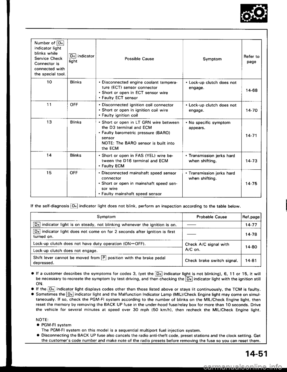
Number of @indicator light
blinks while
Service Check
Connector is
connected with
the special tool.
@ indicator
lightPossible CauseSymptomRefer to
page
'loBlinksDisconnected engine coolant tempera-
rure (ECT) sensor connector
Short or open in ECT sensor wire
Faulty ECT sensor
Lock-up clutch does not
engage.14-68
1lOFFDisconnected ignition coil connector
Short or open in ignition coil wire
Faulty ignition coil
. Lock-up clutch does not
engage.'t 4-7 0
13Blinks. Shon or open in LT GRN wire between
the D3 terminal and ECM. Faulty barometric pressure {BARO)
sensor
NOTE: The BARO sensor is built into
the ECM
. No specific symptom
appears.
14-7 1
14Blinks. Short of open in FAS {YEL} wire be-
tween the D16 terminal and ECM. Faulty ECM
. Transmission jerks hard
when shitting.
't5OFFDisconnected mainshaft speed sensor
connecror
Short or open in mainshaft speed sen-
sor wire
Faulty mainshaft speed sensor
. Transmission jerks hard
when shifting.
14-75
SymptomProbable CauseRet.page
LQ! indicator light is on steady, not blinking whenever the ignition is on.14-77
[Q3] indicator light does not come on for 2 seconds after ignition is first
turned on.14-78
Lock-up clutch does not have duty operation (ON-OFFI.Check A/C signal with
A/C on.14-80Lock-up clutch does not engage.
Shitt leve. cannot be moved lrom @ position with the brake pedal
depressed.Check brake switch signal,14-41
It the self-diagnosis LQ4 indicator light does not blink, perform an inspection according to the table below.
a lf a customer describes the symptoms for codes 3, (yet the LQ! indicator light is not blinkingl, 6, 1 1 or 15, it will
be necessa.y to recreate the symptom by test driving. and then checking the @ indicator light with the ignition still
oN.
e lt ttre @ indicator light displays codes olher than those listed above or stays lit continuously, the TCM is faulty.. Sometimes the Lqd indicator light and the Malfunction Indicator Lamp (MlL)/Check Engine light may come on simul-taneously. lf so, check the PGM-Fl system according to the numbe. of blinks on the MIL/Check Engine light. thenreset the memory by removing the BACK UP fuse in the unde.-hood fuse/relay box for more than 1O seconds. Drive
the vehicle for several minutes at speed over 30 mph (5O km/h), then recheck the MIL/Check Engine light.
NOTE:
. PGM-FI system
The PGM-Fl system on this model is a sequential multiport fuel injection system.a Disconnecting the BACK UP luse also cancels the radio anti-theft code. preset stations and the clock setting. Get
the fuse so vou can reset them.the customer's code number and make note ot the radio
14-51
Page 449 of 1413
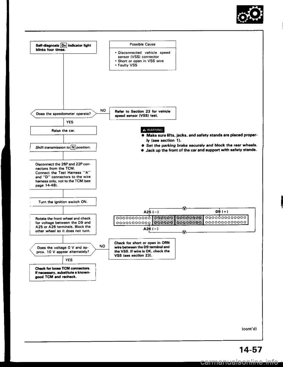
S. d.gno.b lql indic.to. lightbllnkr tour tlm...
R.lor to Soctlon 23 for vohiclerpood lonsoi {vSSl to!t.
Shift t.nsmisiion to A position.
Ch6ck to. shoft or opon in OFilwlro b€twoen tho .)9 t6tminsl andrho VSS. lf wiro is OK, ch€ck thoVSS lsoo soction 231.
Doss lhe voltage O V and ap-p.ox. 10 V appe.r alternately?
Ch.d( tor loo.. TCM co.!n.cto.r.ll nacaaalay, lubrtituta ! known_geod TCM and t chock.
Possible Caus6
. Disconnectsd vehicle speedsensor {VSS} connector. Short or open in VSS wire. Faulty VSS
Disconn6ct the 26Pand 22P con-n.ctors trom th€ TCM.Connect ths Tgst Harnoas "A"
8nd "O" connectors to tho wireharnsss only, not to the TCM (see
page 1+49).
Turn the ignilion switch ON.
a Mak€ sure lifts,lacks, and safety stands aro placod plopor-
ly {see Eaclion 1}.
a S6t th6 parking brake eecurely and block tho tear wh6ol3'
a Jack up tho f.ont ot tho car and rupport whh sstoty standa.
(cont'd)
Rotat€ th€ tront wh6ol and chsckfo. volt6g€ botwean the D9 andA25 o. A26 terminals. Block theother whaol 30 it do€s not turn.
14-57
Page 452 of 1413
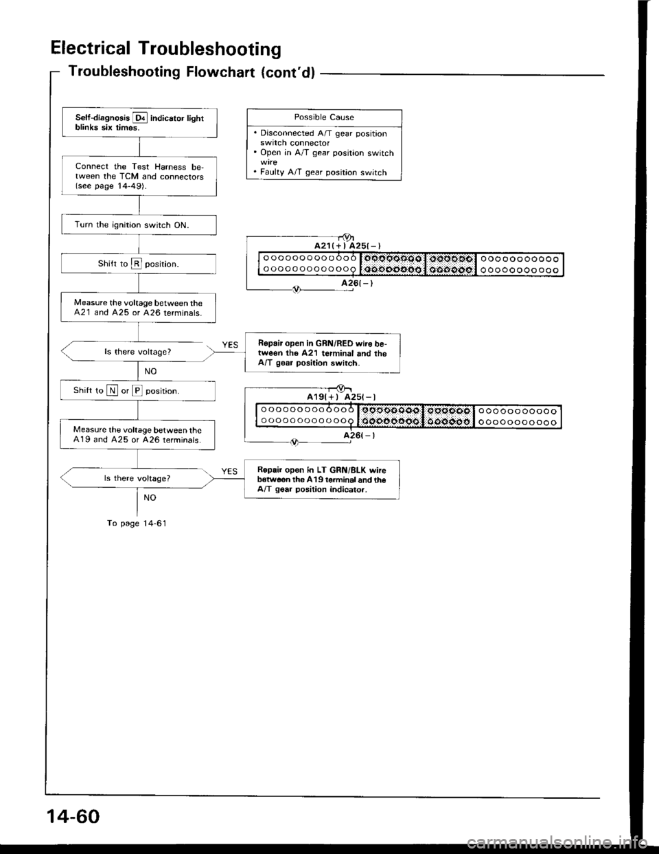
Electrical Troubleshooting
Troubleshooting Flowchart {cont'dl
ls there voltage?
ls there voltage?
NO
To page l4-61
- - r9ta21(+ I A25{-)
Self-diagnosis E indicator lightblinka six timos.
Connect the Test Harness be,tween the TCM and connectors(see page '14-49).
Turn the ignition switch ON.
Measure the voltage between theA21 and 425 or 426 terminals.
Ropair open in GRN/RED wire be,tweon th6 A21 terminal and theA/T gssr position switch.
Shilt ro N or E position.
Measure the voltage between theA19 and A25 or A26 terminals.
Ropair open in LT GRN/BLK wireb€tw6on the 419 torminal and th€A/T gear position indicato..
Possible Cause
. Disconnected A/T gear positionswrtcn connector' Open in A/T gear position switch
. Faulty A/T gear position switch
oooooooooooo
ooooooooooooooooooooooo
ooooooooooo
A25t-l
oooooooooooo
ooooooooooooooooooooooo
ooooooooooo
14-60
Page 456 of 1413
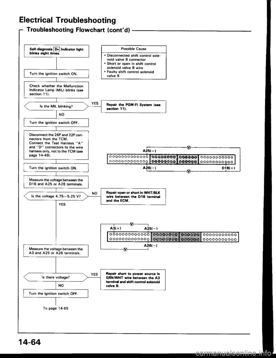
Electrical Troubleshooting
Troubleshooting Flowchart (cont'dl
Possible Cau6e
. Disconnected shift control sole-noid valve B connector. Short or open in shift controlsolenoid valve B wire. Faulty shilt control solenoidvalve B
Solfdiagnolir [!4 Indicato. lightbllnk! eight tim6r.
Turn the ignition switch ON.
Check whother the MalfunctionIndicator Lamp {MlL) blinks (seesection I 11.
Rcpsir rho FGM-FI Syrtem lso6scciion l1l.ls the MIL blinking?
Turn the ignition swirch OFF.
Oisconn€ct the 26P and 22P con-nectors trom the TCM.Connect the Test Harness "A"
and "D" connectors to the wirohamess only. not to the TCM {sesp6ge 14-49).
Turn the ignition switch ON.
Measure the voltage betwe€n theD18 and A25 or A26 terminals.
Ropeir opon or short in WHT/BLKwiro trotweon th6 D18 termineland tho EcM.
ls the voltage 4.75-5.25 V?
Measure the voltage between th€A3 and A25 or A26 terminals.
Ropair rhort to powor rourco inGR /WHT wir6 b€twgan tho A3tormirEl and shift conLol lolonoidvalve B.
Turn the ignition switch OFF.
A2s( - |
DlA( + I
o oooooooooo
ooooooooooooo oo ooo ooooo
oooo o o oo
To page