Automatic HONDA INTEGRA 1994 4.G Owner's Manual
[x] Cancel search | Manufacturer: HONDA, Model Year: 1994, Model line: INTEGRA, Model: HONDA INTEGRA 1994 4.GPages: 1413, PDF Size: 37.94 MB
Page 194 of 1413
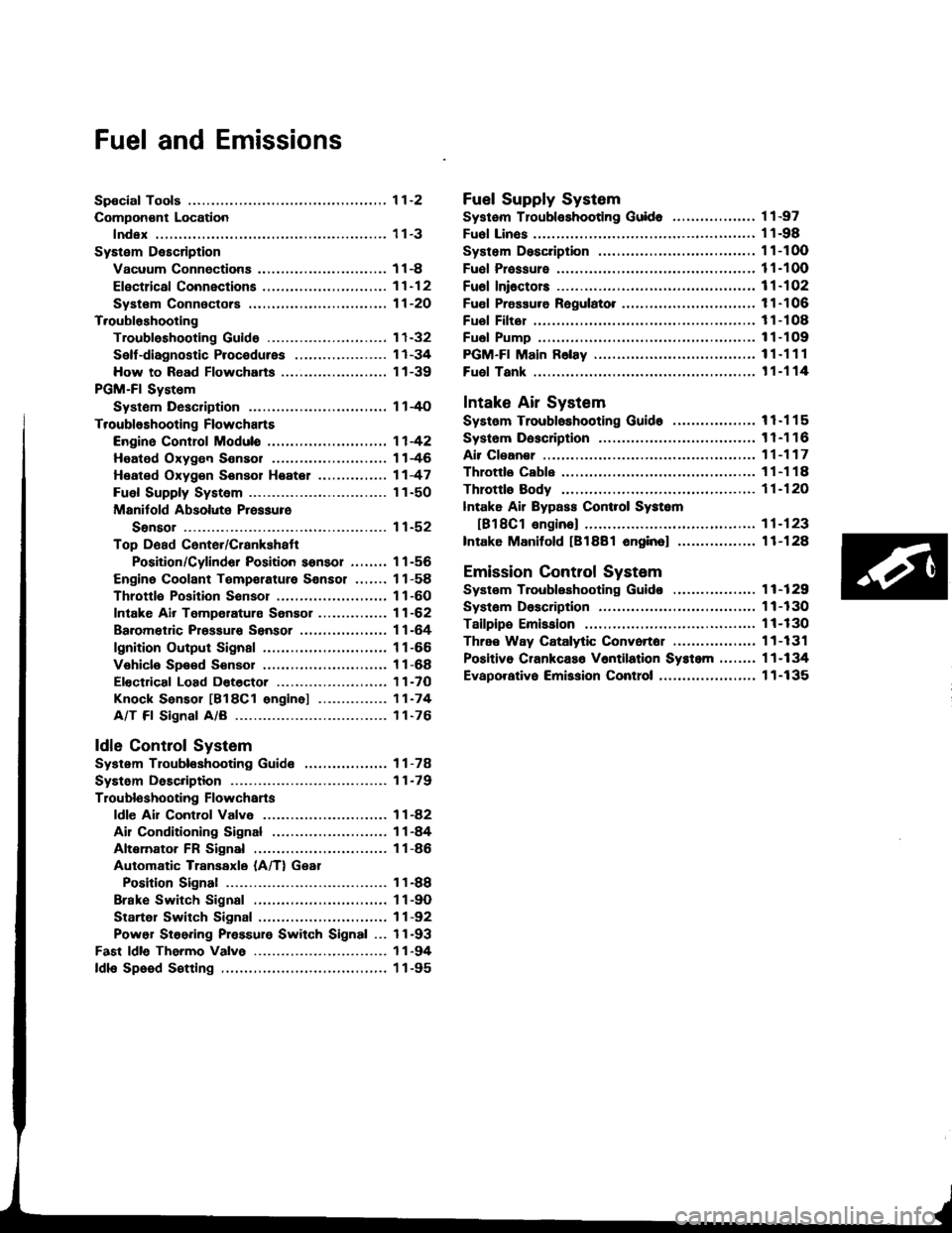
Fuel and Emissions
Spocial Tools ................ 1 1-2
Compon€nt Location
lndex ................. ...... 11-3
System Description
Vacuum Connectiona .......,.................... 1 1 -8
Efectrical Connections ....,.,.,......,...,,.....,'11-12
Syst€m Connectors ...,...,.................-.--. 11-2O
T.oubloshooting
Troubleshooting Guido .......................... 1 1-32
Self -diagnostic Procedures .,..,............... 1 1 -34
How to Road Flowcharts ...................,... 11-39
PGM-Fl System
Systom Description .............................. 1 l-4O
Troubleshooting Flowcharts
Engine Control Moduls ............... ........... 1 1 -42
Heated Oxygon Sensor ......,.................. 1 1-46
Heated Oxyg€n Sonsol Heatel .....,......... 1 1 -47
Fuel Supply System ..............-............... 1 1-50
Manitold Absolute Pressure
Ssnsor ............................................ 1 1-52
Top D6ad Cente./Crankshatr
Position/Cylindor Position sonsor ........ 1 1 -56
Engine Coolant Tempsrature Sonsor ....... 11-58
Throttlo Position Sonsor ........,..,,........... 1 1-60
Intake Air Temperaturs Sensor ............... 11-62
Baromet c Prsssuro Sensor ......,...,...,..,. 11-64
lgnition Output Signal ........................... 1 1 -66
Vehicle Spe€d Sensor ........................... 1 1 -68
Electdcal Load Dotector ....,...,..........,.... 1 1 -7O
Knock Sensor [818C1 engine] ............... 11-74
A/T Fl Signal A/B ................................. 1 1-76
ldle Contlol System
System Troubleshooting Guide .................. 1 1 -78
Systom Description ........ 11-79
Troubloshooting Flowchans
ldl€ Ail Control Valve ........................... 1 1 -82
Ail Conditioning Signal ......................... 1 1 -84
Altemator FR Signal ............................. 1 1 -86
Automatic Transaxle (A/T) Gear
Position Signal ......... 11-88
Brake Switch Signal ............................. 1 1 -9O
Startel Switch Signal ............................ 11-92
Power Steering Pressure Switch Signal ... 11-93
Fast ldle Thermo Valve ...................,......... 1 1 -94
ldls Speed S€tting .................................... 1 1 -95
Fuel Supply System
Systam Tloubloshooting Guid. .................. 1 1 -97
Fuol Linos ...................... 1'l -98
System Description ........ 11-100
Fuol Prassure ................. 11-100
Fu6l Ini6ctors ................. 11-102
Fuel Pressure Ragulato. .,. 11-106
Fuel Filter ...................... 11-108
Fual Pump ..................... 11-109
PGM-Fl Main F6lay ................................... 1 1"1 1 1
Fuel Tank ...................... t 1-114
Intake Air System
System Troubloshooting Guido .................. 1 1 -1 1 5
Systom Dascription ........ 11-116
Air Clean€r .................... 11-117
Throttls Cable ................'11-118
Throttl8 Body ................ 11-120
lntake Air Bypass Cont.ol Systsm
[B18Cl enginal .,......... 11-123
Intake Manilold [B1881 onginol ................. 11-128
Emission Control System
Systsm Troubleshooting Guido .................. 1 1 -1 29
Systam Doscription ........ 11-130
Tailpips Emission ........... 11-130
Thrae Way Catalytic Convortor ...,...,........., 11-131
Positiva CrankcaEo V6ntilation Systcm .,....., 11-134
Evaporativo Emission Contro|,..,..,.,.,,.,,..,.., 1 1-135
Page 238 of 1413
PGM-FI System
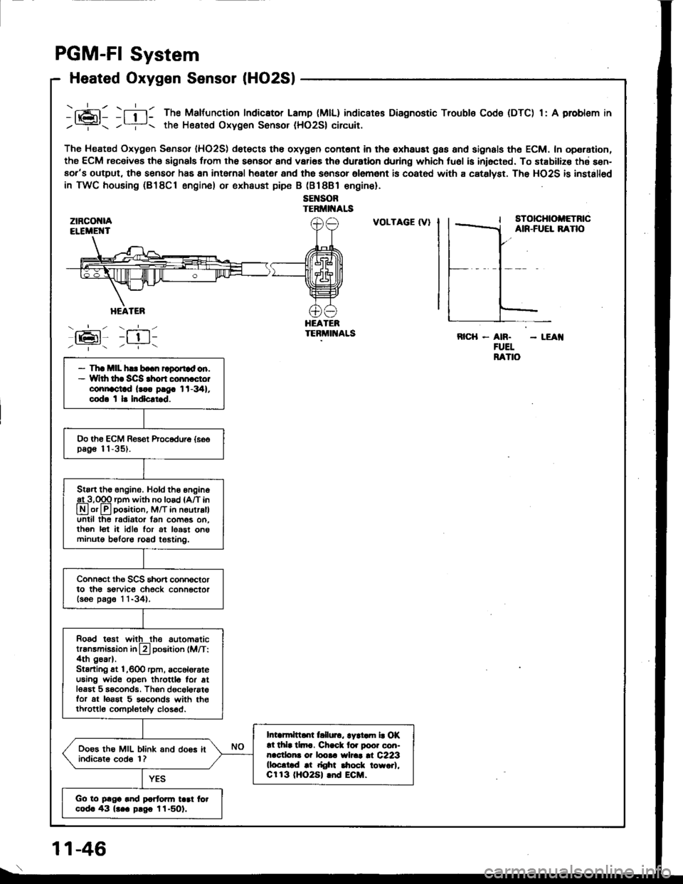
Heated Oxygen Sensor lHO2Sl
ztRcot{lAELEiIE'{T
HEATER
- --.'!- - -__-
lrPl _l !l-
-fi-l: The Malfunction Indicator Lamp (MlL) indicates Diagnostic Troubls Code (DTC) 1: A problsm in
/? the Heated Oxygen Sonsor (HO2S| circuit.
The Heated Oxygen Sensor IHO2S) det€cts th6 oxygon contont in th6 exhaust gas and signals th6 ECM. In operation,
the ECM receiv€s th6 signals trom the sensor and vari€s the duration during which tu6l is iniocted. To stabilize thd sen-aor's output, tho sensor has 8n intarnal heater and the sensor olemant is coatod with a catslyst. The HO2S is installod
in TWC housing (B18Cl engine) or exhaust pipe B (Bl8Bl €ngine).
sEl{SORTERMII{ALS
:tz-t6l-/ --.- \
VOLTAGE (V}sTotcHtoltETncAIR-FUEL BANO
HEATEBTEBMIT{ALSRICH - AN. - LEAI{FUELRATIO- Th! mll h.. bo.n raportad on.- Wlth thr SCS rhon coon cto.connoctad lr.. p!9. 1t-341,cod. t l. Indlcltrd.
Oo th€ ECM Res€t Procodure {soopag€ 11-35).
Stan the 6ngine. Hold th6 engine
A3,qgq rpm with no load {A/T in
Lryl or lll position, M/T in nourralluntil the radiator lan com6s on.then lot it idle lor ot least on6minutg beforo road t€6tin0.
Connoct ths SCS short connoctorto th6 sorvic€ check connectorlsoo p.g6 1 1-34).
Rood t€st witlthe automatictransmission in L?l position (M/T:4th gear).Stsrting st l,600 rpm, acc6lorateu6ing wide open throttlo for atlesgt 5 seconds. Thsn dgcol€rstefor at lorst 5 s€conds with th€throttlo completoly closed.
Intarmittd[ t llurc, lyri.m b Of!l thla tlmc. Ch.ck lor poor con-nacdona o? loota wlrat |l C223(loc.trd at right $ock towo.l,Cr 13 (HO2S| lnd ECM.
Ooes the MIL blink and doos itindic6t6 cod6 1?
Go to plga and partonn tad fotcod. 43 lr.a p.go l1-501.
1 1-46
Page 267 of 1413
ldle Gontrol System
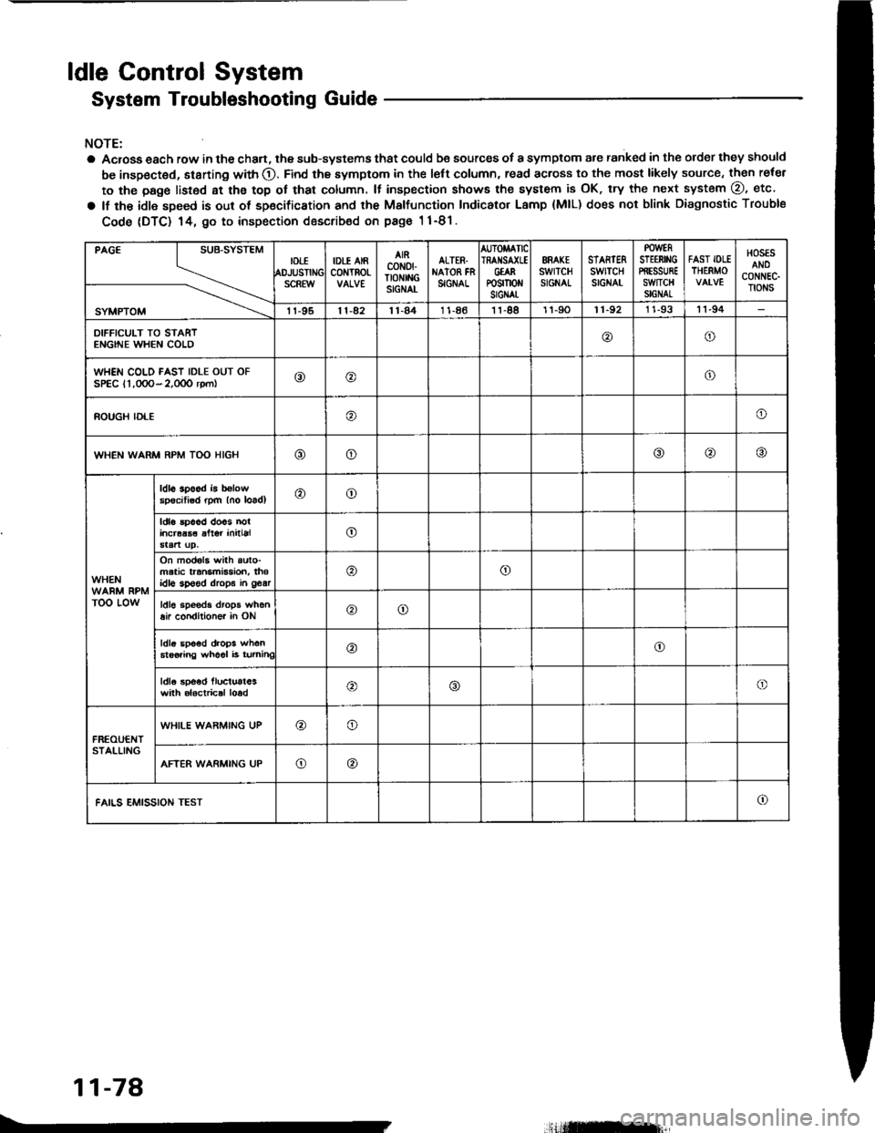
System Troubleshooting Guide
NOTE:
a Acrosa each row in the chan, the sub-systems that could be sources of a symptom are ranked in the order they should
be inspected, starting with O. Find the symptom in the left column, read across to the most likely source, then reler
to the page listsd at ths top ot that column. It inspection showa the system is OK, try the next system @, etc.
a lf the idle speed is out of sp€cification and th€ Malfunction Indicator Lamp {MlL) does not blink Diagnostic Trouble
Code (DTC) 14, 9o to inspection describ€d on pags 1 1-81.
PAGE
SYMPTOM
IDTIOJUSTIiSCREW
IDLE AIRc0NTROt-
AIRcoN0fTtoNtitcSIGNAL
ALTER.NAION FNSIGNAL
AUTOMATICIRAI{SA(LEGtARP0sm0 stGIAt
ERAK€swrTcHSIGNAL
STARTERswtTcHSIGNAT
POWERSTEERII'IGPffESSUREswncHSIGNAL
FAST IOLETHERMO
HOSESANOCONNEC.TIONS
11-9511-4211-841 1-8611-8811-9011-92I 1-9311-94
DIFFICULT TO STARTENGINE WHEN COLD@o
WHEN COLD FAST IDLE OUT OFSPEC l1,0OO- 2,0OO rpm|o@o
ROUGH IDLEo
WHEN WARM RPM TOO HIGHooo
WHEN
TOO LOW
ldl6 3p6od b b€lowspecitisd rpm (no loadl@o
ldla 5p66d doos nolincraas€ alter initialo
On mod6l3 with auto-matic transmBsion, thsidlo sp€ed drops in 963ro
ldl6 sp€eds drops when8ir condilioner in ONoo
ldls spo6d drops when6ts6iing wh66l i6 turninC@o
ldla spoed lluctust63with alactrical loado
FREOUENTSTALLING
WHILE WARMING UP@o
AFTER WARMING UPo@
FAILS EMISSION TESTo
11-78
.,Hilffirl|,
Page 277 of 1413
ldle Control System
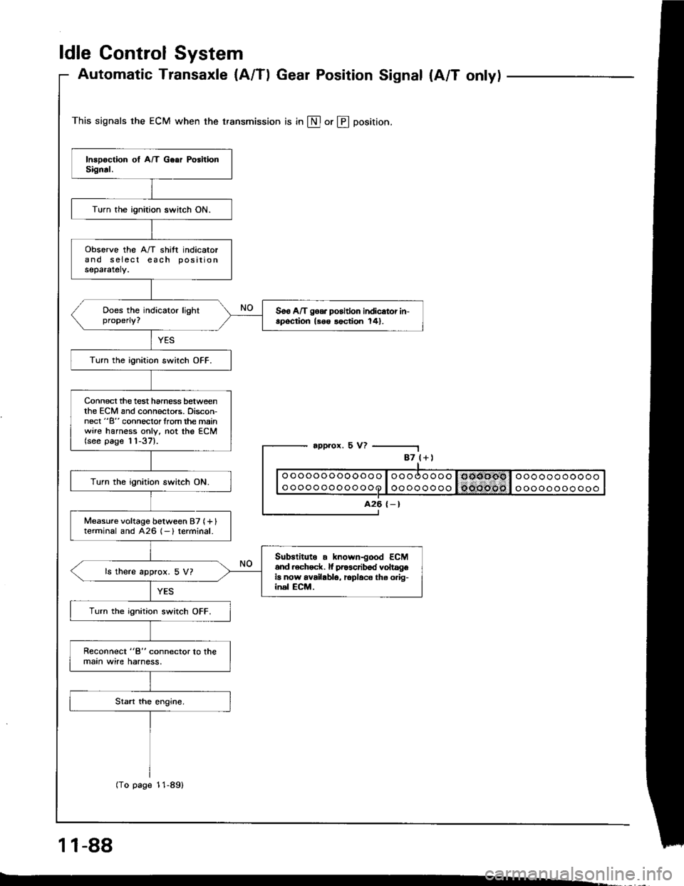
Automatic Transaxle {A/Tl Gear Position Signal {A/T onlyl
This signals the ECM when the transmission is in @ or @ position.
appror. 5 V?
1 1-88
-.
87 l+)
ooooooooooooo
oooooooooooo
A26 {-}
Turn the ignition switch ON.
obsorve the A/T shift indicatorand s eiecl each positionseparately.
Soo A/T goa. position indicator in-spoqtion ls6o lection 141.
Turn the ignition switch OFF.
Connect the test hamess betweenthe ECM and connectors. Discon-nect "B" connoclorlrom the mainwire harness only, not the ECM(see page 11-37).
Turn the ignition switch ON.
Measure voltage between 87 (+ Iterminal and 426 1- ) terminal.
Subslituto . known-good ECM6nd .ech6ck. lf pr63cribod voltageia now availablo, rcplaco ths o.ig-inel ECM.
ls there approx. 5 V?
Turn the ignition switch OFF.
Reconnect "8" connector lo lhemaan wire harness.
(To page 11-89)
Page 298 of 1413
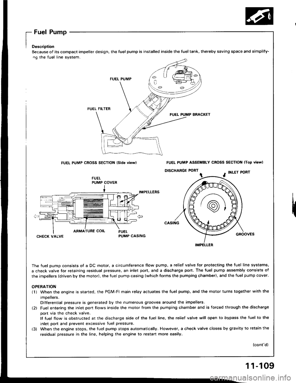
[":::,::-'
Eecause of its compact impeller design, the fuel pump is installed inside the fueltank, thereby saving space
ng the fuel line system.
FUEL PUMP
FUEL FILTER
FUEL PUMP BRACKET
FUEL PUMP CROSS SECTION lsido vi6rvl
IMPELLERS
CHECK VALVEPUMP CASING
The fuel oumo consists of a DC motor, a circumference flow pump, a relief valve for ptotecting the fuel lir
a check valve for retaining residual pressure, an inlet port, and a discharge port. The fuel pump assembly
the impellers (driven by the motor), the fuel pump casing {which forms the pumping chsmber), and the fuel p
OPERATION(1 ) When the engine is started. the PGi/t-Fl main relay actuates the fuel pump, and the motor turns togeth
impellers.
Differential pressure is generated by the numerous grooves around the impellers.
(2) Fuel entering the inlet porr flows inside the motor from the pumping chambe. and is forced through th
port via the check valve.
lf tuel flow is obstructed at the discharge side of the tuel line, the relief valve will open to bypass the
inlet port and prevent excessive fuel pressure.
(3) When the engine stops, the tuel pump stops automatically. However, a check valve closes by gravity t
residual pressure in the line, helping the engine to aestan more easily.
and simplify-
N lTop vi6w)
PORT
GROOVES
fuel line systems,
embly consists of
fuel pump cover.
together with the
rgh the discha.ge
ss the fuel to the
avitv to retain the
(cont'd)
PUMP COVER
FUEL PUMP ASSEMBLY CROSS SECTION
D|SCHARGE FORT ^ . tNLEr P
IMPELLER
11-109
Page 330 of 1413
Transaxle
Clutch
Manual Transmission ......................
Automatic Transmission ..................
Differential
Manual Transmission
81881 engine
818C1 engine
Automatic Transmission ...............
Driveshafts
12-1
13-1
14-1
15-1
15-9
15-19
16-1
Page 393 of 1413
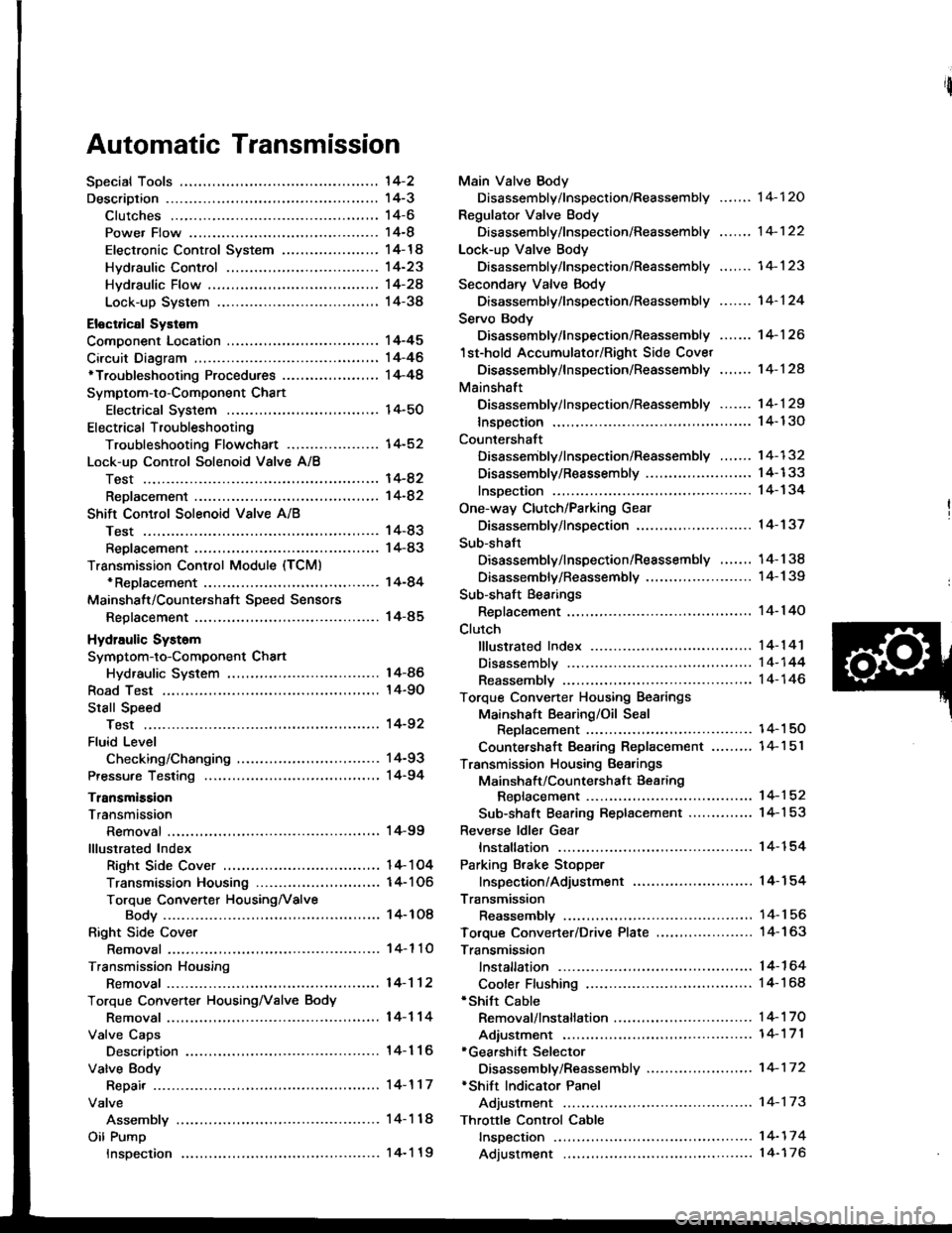
Automatic Transmission
'l4-2
14-3't 4-6
14-8
14-14
14-23
Hvdraulic Flow ...--...... 14-24
Lock-up System ........ 14-38
Eloctrical Systom
Component Location ............,...,................ I 4-45
Circuit Diagram ............. 14-46'Troubleshooting Procedures ........,..........., l4-48
Symptom-to-Component Chart
Electrical System ...... 14-50
Electrical Troubleshooting
Troubleshooting Flowchart .................... 14-52
Lock-uo Control Solenoid Valve A/8
Test .................. --.... \4-82
ReDlacement ,...,...,..,. 14-82
Shift Control Solenoid Vslve A/B
Test .................. ...... 14-83
Reolacement .............. 14-83
Transmission Control Module (TCM)*ReDlacement ........... 14-84
Mainshalt/CountershaJt SDeed Sensors
Reolacement ............. 14-85
Hydraulic Systom
Symptom-to-Component Chart
Hydraulic System
Road Test
Slall Speed
Test ..................
Fluid Level
Checking/Changing
Pressu.e Testing
Transmission
Transmission
Removal ............. ...... 14-99
lllustrated Index
Right Side Cover .................................. 1 4- 1 04
Transmission Housin9 ..................,,....... I 4-1 06
Torque Converter HousingNalve
Body .................. ... 14- 1O8
Right Side Cover
Removal ............. ...... 14-110
Transmission Housing
Removal ............. .-..-. 14-112
Torque Convener HousingNalve Body
Removal ............. ...... 14-114
Valve Caps
Description ................ 14-116
Valve Body
Repair ................ ...-.. 14-117
Valve
Assembly ...........
Oil Pump
Main Valve Body
Disassembly/lnspection/Reassembly
Regulator Valve Body
Disassembly/lnspection/Reassembly
Lock-up Valve Body
Disassembly/lnspection/Reassembly .......
Secondary Valve Body
Disassembly/lnspection/Reassembly .......
Servo Body
Disassembly/lnspection/Reassembly .......
1st-hold Accumulator/Right Side Covet
Oisassembly/lnspection/Reassembly .,..,..
Mainshaft
Disassembly/lnspection/Reassembly -.. -... 1 4- 1 29
lnsDection ................. 14- 130
Countershaft
Disassembly/lnspection/Reassembly ....... 14-132
Disassembly/Reassembly ....................... 1 4-1 33
lnsDection ................. 14-134
One-way Clutch/Parking Gear
Disassembly/lnspection .................... -.. -. 1 4-137
Sub-shaft
Disassembly/lnspection/Reassembly ....... 14-138
Disassemblv/Reassemblv ....................... 1 4-1 39
Sub-shaft Bearings
Replacement ............. l4-140
Clutch
fllustrated lndex ................. -..-...-.......... 14-1 41
Disassembly ,,,.,,........ 14-144
Reassembly .............. 14-146
Torque Converter Housing Bearings
Mainshaft Bearing/Oil Seal
Reolacement ......... 14-1 50
Countershaft Bearing Replacement .......,, 14-1 5l
Transmission Housing Bearings
Mainshsft/Countershaft Bearing
Repfacement ...-..-..14-152
Sub-shaft Bearing Replacement .............. 1 4-1 53
Reve.se ldler Gear
lnstallation ................ 14-154
Parking Brake Stopper
lnspection/Adjustment ..........................'14-'154
Transmission
Reassemblv .............,. .14_156
Toroue Converter/Drive Plate ..,..,............... 1 4- 1 63
Transmission
14-120
14-122
14-123
14-124
14-126
14-124
14-86
14-90
't4-92
14-93
14-94
lnstallation
Cooler Flushing'Shitt Cable
Removal/lnstallation ..............................
Adiustment ...-..-......-. 14-'171*Gearshift Selector
Disassembly/Reassembly .....................,. 1 4-17 2*Shift Indicator Panel
Adjustment -..........-...14-173
Throttle Control Cable
fnspection .......,..,...... 14-17 4
Adjustment .............. 14-176
14-164
14-168
14-'t 7 0
Inspection
Page 395 of 1413
The Automatic Transmission is a combination of a 3-e,ement torque convefter and triple-shaft electfonically controlled
automatic transmission which provides 4 speeds forward and 1 speed reverse. The entire unit is positioned in line with
the engine.
Torque Converter, Gears and Clutches
The torque converter consists of a pump, turbine and stator assembly in a single unit, The torque converter is connected
to the engine crankshaft so they turn together as a unit as the engine turns. Around the outside of the torque converter
is a ring gear which meshes with the starter pinion when the engine is being staned. The entire torque converter assem-
bly serves as a flywheel while transmitting power to the transmission mainshaft.
The transmission has three parallel shafts, the mainshaft. countershaft and sub-shaft. The mainshatt is in line with the
engine crankshaft.
The mainshaft includes the clutches for 1 st, and 2ndl4th, and gears for 3rd. 2nd, 4th, reverse and l st (3rd gear is in-
tegral with the mainshaft, while reverse gear is integral with the 4th gear).
The countershaft includes the 3rd clutch and gears Ior 3rd, 2nd,4th, reverse, lst and parking. Reverse and 4th gears
can be locked to the countershaft at its center, providing 4th gear or reverse, depending on which way the selector is moved.
The sub-shaft includes the lst-hold clutch and gears for 1st and 4th
The gears on the mainshait are in constant mesh with those on the countershaft and sub-shaft. When certain combina-
tions of gears in the transmission are engaged by the clutches, power is transmitted from the mainshaft to the counter-
shaft via the sub-shatt to provide @, E, tr. tr and @ position.
Electronic Control
The electronic control system consists of the Transmission Control Module {TCM), sensors, and 4 solenoid valves. Shift-
ing and lock-up are electronically controlled for comfortable driving under all conditions.
The TCM is located below the dashboard, behind the left side kick panel on the driver's side.
Hydraulic Control
The valve bodies include the main valve body, secondary valve body, regulator valve body. servo body, and lock-up valve
body throuqh the respective separator plates.
They are bolted on the torque converter housing.
The main valve body contains the manual valve, 1-2 shift valve, 2-3 shift valve, Clutch Pressure Cont.ol (CPC) valve,
4th exhaust valve, relief valve, and oil pump gears.
The secondary valve body contains the 4-3 kick-down valve,3-2 kick-down valve,2-3 orifice cont.ol valve, 3-4 shitt
valve, orifice control valve. modulator valve, and servo control valve
The regulator valve body contains the pressure regulator valve. lock-up control valve, torque converter check valve, and
cooler check valve.
The servo bodv contains the servo valve which is integrated with the reverse shift fork, throttle valve B, and accumulators.
The lock-ug valve bodv contains the lock-up shift valve and lock-up timing B valve. and is bolted on the secondary valve
body.
Fluid from the regulator passes through the manual valve to the various control valves.
Shitt Control Mochanism
Input to the TCM i.om various sensors located throughout the car determines which shift control solenoid valve should
be activated.
Activating a shift control solenoid valve changes modulator pressure, causing a shift valve to move. This pressurizes
a line to one of the clutches. engaging that clutch and its corresponding gear.
Lock-up Mechanism
In @ position. in 2nd, 3rd and 4th, and E position in 3rd, pressurized tluid can be drained from the back of the tor-
que converter through an oil passage, causing the lock-up piston to be held against the torque converter cover. As this
takes Dlace, the mainshaft rotates at the same speed as the engine crankshatt. Together with hydraulic control, the TCM
optimizes the timing ol the lock-up mechanism.
The lock-up valves control the range of lock-up according to lock-up control solenoid valves A and B, and throttle valve B
When lock-up control solenoid valves A and B activate, modulator pressure changes. Lock-up control solenoid valves
A and B are mounted on the torque converter housing, and are controlled by the TCM.
(cont'd)
14-3
Page 396 of 1413
![HONDA INTEGRA 1994 4.G Owners Manual Description
(contd)
Gear Selection
The selector lever has seven posirions; E PARK, E REVERSE, N NEUTRAL, @ 1st through 4th positions. E 1st
through 3rd positions, Ql2nd gear and [] 1st gear.
Starting HONDA INTEGRA 1994 4.G Owners Manual Description
(contd)
Gear Selection
The selector lever has seven posirions; E PARK, E REVERSE, N NEUTRAL, @ 1st through 4th positions. E 1st
through 3rd positions, Ql2nd gear and [] 1st gear.
Starting](/img/13/6067/w960_6067-395.png)
Description
(cont'd)
Gear Selection
The selector lever has seven posirions; E PARK, E REVERSE, N NEUTRAL, @ 1st through 4th positions. E 1st
through 3rd positions, Ql2nd gear and [] 1st gear.
Starting is possible only in @ and I Oosition through use ot a slide-type, neutral-safety switch.
Automatic Tlansaxle {A/T) Gear Position Indicatol
A/T gear pos;tion indicator in the instrumenl panel shows what gear has been selected without having look down at
the console.
Position Description
l3?]] PARK Front wheels locked; parking pawl engaged with parking gear on countershatt. All clutches
reteaseo,
[R] REVERSE Reverse; reverse selector engaged with countershalt reverse gear and 4th clutch locked.
N NEUTRAL All clurches released.
D+l DRIVE General driving; starts off in 'lst, shifts automatically to 2nd, 3rd, then 4th, depending on vehicle
('lst through 4th) speed and throttle position. Do'vnshifts through 3rd, 2nd and 1st on deceleration to stop.
The lock-up mechanism comes into operation in 2nd, 3rd and 4th when the transmission in lDtposrtron.
Dgi DRIVE For rapid acceleration at highway speeds and general driving; starts off in 1st. shifts automatical-(1st through 3rd) ly to 2nd then 3rd, depending on vehicle speed and throttle position. Downshifts through lower
gears on deceleration to stop. The lock-up mechanism comes into operation in 3rd.
El SECOND Driving in 2nd geari stays in 2nd gear, does not shift up and down.
For engine braking or better traction starting off on loose or slippery surfece.
L]l FIRST Driving in 1st gear; stays in lst gear, does not shilt up.
For engine braking.
14-4
Page 398 of 1413
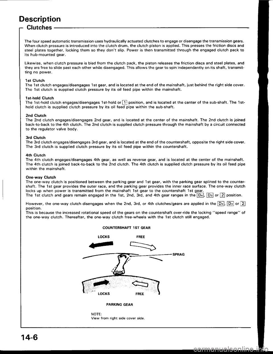
Description
Clutches
The four speed automatic transmission uses hydraulically actuated clutches to engage or disengage the transmission gears.
When clutch pressure is introduced into the clutch drum, the clutch piston is applied. This presses the iriction discs and
steel plates together, locking them so they don't slip. Power is then transmitted through the engaged clutch pack tojts hub-mounted gear.
Likewise, when clutch pressure is bled from the clutch pack. the piston releases the friction discs and steel plates, and
they are {ree to slide past each other while disengaged. This allows the gear to spin independently on its shaft, transmit-
ting no power.
1st ClutchThe l st clutch engages/disengages 1st gear, and is located at the end of the mainshaft, just behind the right side cover.
The 1st clutch is supplied clutch pressure by its oil feed pipe within the mainshaft.
1st-hold clutchThe 1st-hold clutch engages/disengages 1st-hold or I Fosition, and is located at the center ol the sub-shaft. The 1st-
hold clutch is supplied clulch pressure by its oil feed pipe within the sub-shait.
2nd ClutchThe 2nd clutch engages/disengages 2nd gear, and is located at the center of the mainshaft. The 2nd clutch is joined
back-to-back to the 4th clutch. The 2nd clutch is supplied clutch pressure through the mainshaft by a circuit connected
to the regulator valve body.
3rd Clutch
The 3rd clutch engages/disengages 3rd gea.. and is located at the end oJ the countershaft, opposite the right side cover.
The 3rd clutch is supplied clutch pressure by its oil feed pipe within the countershaft,
4th clurch
The 4th clutch engages/disengages 4th gear. as well as reverse gear, and is located at the center of the mainshaft.
The 4th clutch is joined back-to-back to the 2nd clutch. The 4th clutch is supplied clutch pressure by its oil feed pipe
within the mainshalt.
One-way Clutch
The one-way clutch is posjtioned between the parking gear and 1st gear. with the parking gear splined to the counter-
shaft. The 1st gear provides the outer race, and the parking gear provides the inner race surface. The one-way clutch
locks up when power is transmitted from the mainshaft 1st gear to the countershaft lst ggel _The 1st clutch and gears remain engaged in the 1st. 2nd. 3rd, and 4th gear ranges in the @, E or E position.
However, the one-way clutch disengages when the 2nd. 3rd, or 4th clutches/gears are applied in the E, lD.l o, Eoosttton.
This is because the increased rotational speed of the gears on the countershaft over-ride the locking "speed range" of
the one-way clutch. Thereafter, the one-way clutch free-wheels with the lst clutch still engaged.
COUNTERSHAFT 1ST GEAR
FREE
:>
LOCKS
aF
NOTE:View trom right side cover side.
14-6