engine coolant HONDA INTEGRA 1994 4.G Owner's Manual
[x] Cancel search | Manufacturer: HONDA, Model Year: 1994, Model line: INTEGRA, Model: HONDA INTEGRA 1994 4.GPages: 1413, PDF Size: 37.94 MB
Page 249 of 1413
PGM-FI System
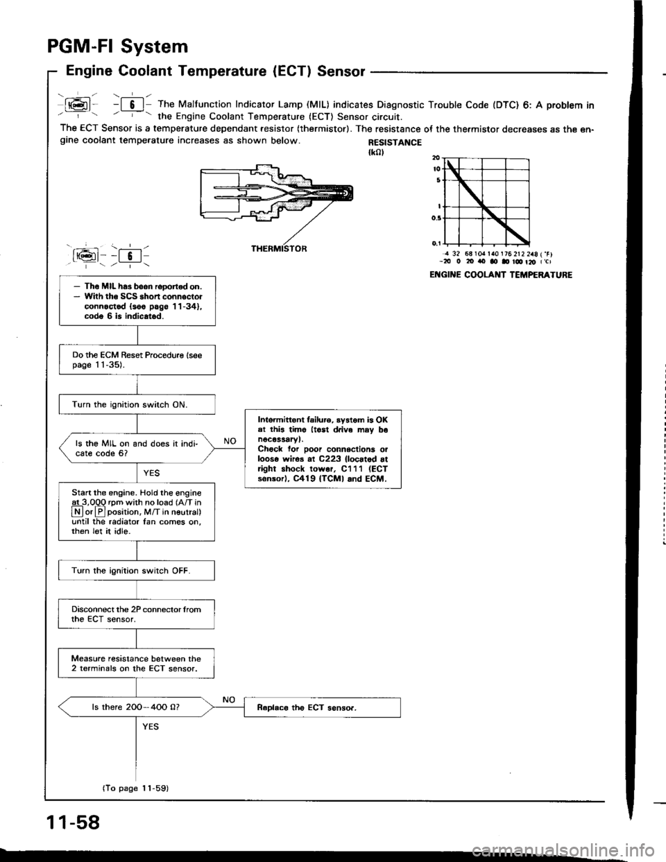
Engine Coolant Temperature (ECT) Sensor
- ,-!-- ---1- -
t@l- -l 6 | The Malfunction Indicator Lamp (MlL) indicates Diagnostic Trouble Code (DTC) 6: A problem in- - the Engine Coolant Temperature (ECT) Sensor circuit.The ECT Sensor is a temperature dependant resistor (thermistor). The resistance oI the thermistor decreases as th€ en-gine coolant tempe.ature increases as shown below.
J rsG-11
RESISTANCE{k0l
- \.--r-l--t 5 | /--i- \
j 32 68lOrr la0 t76 2t2 2a8 (.Fl-2tt 0 20 rto ao D r@ t20 (,cl
ENGII{E COOLAI{T TCMPERATURE- Th€ MIL has boon roDortod on.- Wlth tho SCS shon connoctorconnoctod {s66 pag6 '11-34},
code 6 is indicatod.
Do the ECM Reset Procedu.e lseepage 1 1-35).
Turn the ignition switch ON.
Intoimittont failur6. ryatom is OKel this lime ltosl d.ive may bonocassaryl.Chock for poor connsctiona orlooso wiros al C223 {locatod attight shock lowor, C111 (ECT
sonsorl, C419 {TCMI and ECM.
ls the MIL on and does it indi-cate code 6?
Start the engine. Hold the engineat 3,O0O rom with no load {Afi in
N or lF]position, M/T in neutral)until the radiator lan comes on,then lot it idle.
Turn the ignition swirch OFF.
Disconnect the 2P conneclor lromthe ECT sensor.
Measure resistance between the2 terminals on the ECT sensor.
ls there 2OO-4OO O?
(To page 1 1-59)
11-58
--
Page 269 of 1413
ldle Control System
System Description (cont'd)
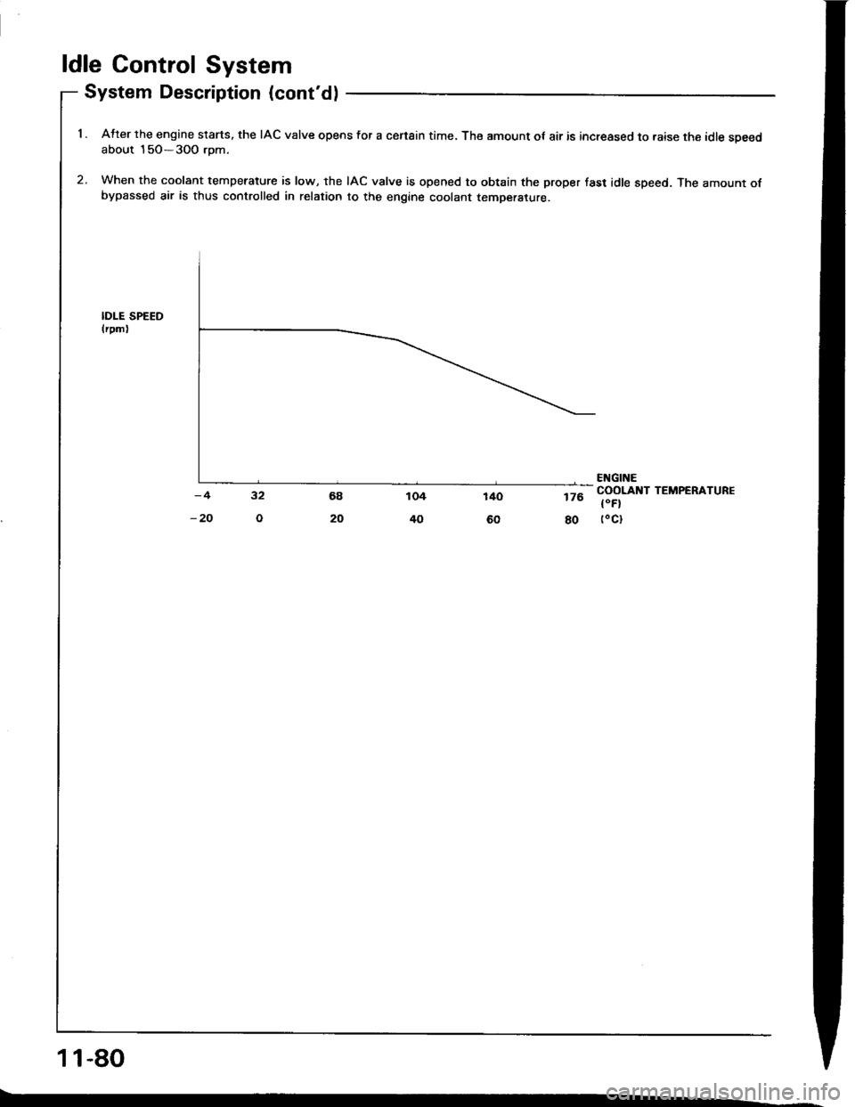
1 . Atter the engine slarts. the IAC valve opens for a censin time, The amount ot air is increased to raise the idle soeedabout 15O-3OO rom.
2. When the coolant temperature is low, the IAC valve is opened to obtain the proper fast idle speed. The amount ofbypassed air is thus controlled in relation to the engine coolant temperature.
IDI-E SPEEDlrpm)
176
80
ENGINECOOLANT TEMPERATURE
t"Fl(oct
11-80
Page 283 of 1413
ldle Control System
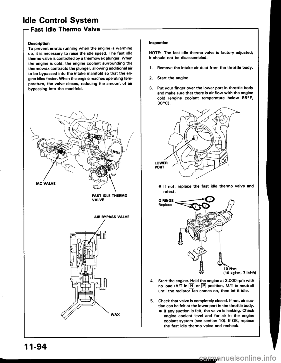
Fast ldle Thermo Valve
DEscliptlon
To prevent erratic running when the engine is warming
up, it is n€cessary to raise the idle speed. The fast idle
thermo valve is controlled by a thermowax plunger, When
the engine is cold. the engine coolant su.rounding the
thermowax contracts the plunger, allowing additional air
to be bypassed into the intake manifold so that the en-
gine idlss taster. When the engine reaches operating tem-
peratur€, the valve closss, reducing the amount of air
bypassing into the manifold.
FAST IDLE THERMOVALVE
AIN EYPASS VALVE
Inspaction
NOTE: The tast idle thermo valve is factory adiustsd;
it should not be disassombl€d.
1. Remove the intake air duct from the throttlg body.
2. Stan the engine.
3. Put your finger over ths lower port in throttle body
and make sure that there is 8ir flow with tho engine
cold (engine coolant temperatute below 86oF,
300c).
a lf not,
retest.
leplace the fast idle thermo valvs and
4.
o-Rr{GsReplace
llo kgf.m, 7 lbt.trl
Start the engine. Hold the sngine at 3.0OO rpm with
no load (A/T in I or @ position, M/T in neutral]
until the radiator fan comes on, then let it idl6.
Check thst valve is completely closed. lt not, air suc-
tion can be telt at the lower Don in the throttle body,
a It any suction is felt, the valve is leaking Check
engine coolant level and for air in tho engine
coolant system (see section 1O). ll OK, rsplace
the fast idle thermo valve and rechock.
11-94
Page 309 of 1413
lntake Air System
Throttle Body
Description
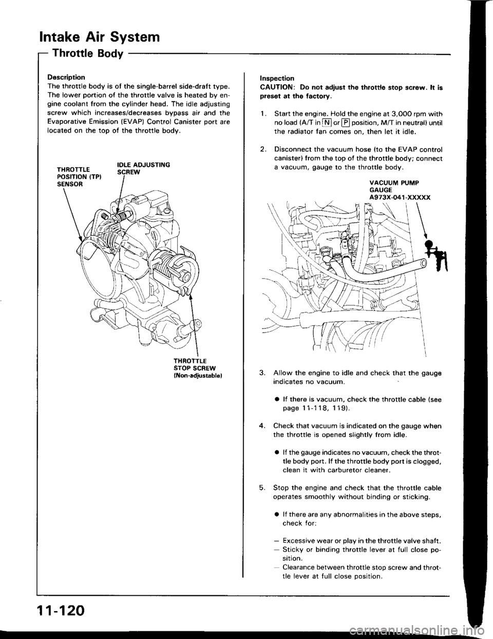
The throttle body is ot the single-barrel side-draft 1ype.
The lower portion of the throttle valve is heated by en-gine coolant from the cylinder head. The idle adjusting
screw which increases/dec.eases bvDass air and the
Evaporative Emission (EVAP) Control Canister port are
located on the top of the throttle body.
IOLE AOJUSTING
THROTTLESTOP SCREW(Non-adiustsb16l
11-120
Insoection
CAUTION: Do not adiust the thlottle stop screw. lt ispreset at the lactory.
1. Start the engine. Hold the engine at 3,OOO rpm with
no load (A/T in S or E position, M/T in neutral) until
the radiator fan comes on, then let it idle.
2. Disconnect the vacuum hose (to the EVAP control
canister) from the top of the throttle body; connect
a vacuum, gauge to the throttle body.
VACUUM PUMPGAUGEA973X-O41-XXXXX
5.
3. Allow the engine to idle and check that the gauge
indicates no vacuum.
a li there is vacuum, check the throttle cable (see
page 1 1-'l 18, 119).
Check that vacuum is indicated on the gauge when
the throttle is opened slightly from idle.
a lf the gauge indicates no vacuum, check the throt-
tle body port. lf the throttle body port is clogged.
clean it with carburetor cleaner.
Stop the engine and check that the throttle cable
operates smoothly without binding or sticking.
a lf there are any abnormalities in the above steps,
check for:
- Excessive wear or Dlav in the throttle valve shaft.
Sticky or binding throttle lever at full close po-
srtron.
Clearance between throttle stop screw and throt-
tle lever at tull close Dosition.
Page 326 of 1413
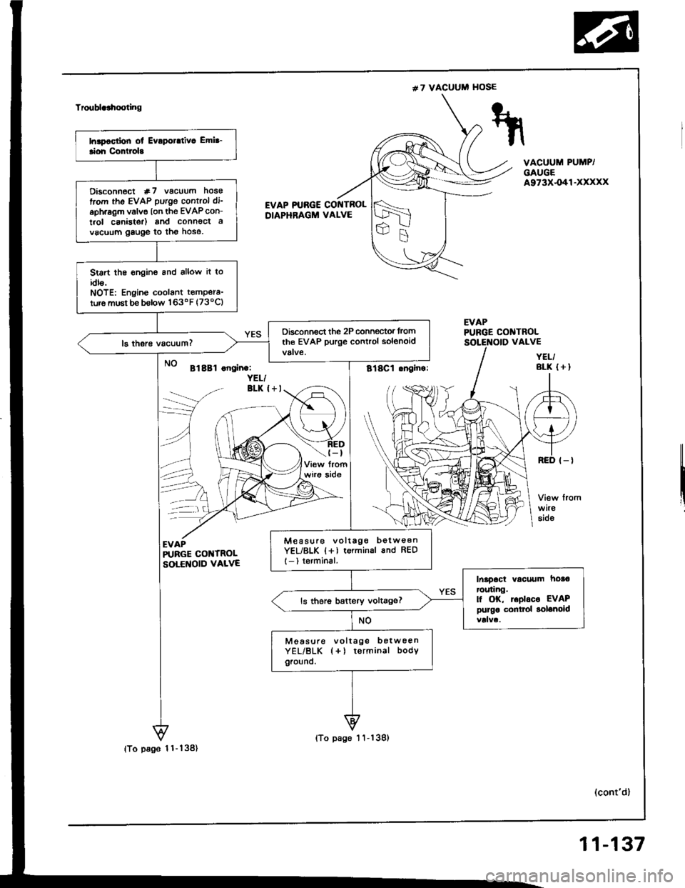
#7 VACUUM HOSE
Troublclhooting
VACUUM PUMP/GAUGEA973X-O41-XXXXX
EVAP PTJBGE COI{TROLDIAPHRAGM VALVE
EVAPPUBGE CONTROL
Bl8Bl .noin.:YEL/BLK I+I
(-t
wirg aide
--\
EVAPR'RGE COI{TROLSOLENOID VALVE
(cont'd)
VALVE
YEL/BLK (+I
Disconn€ct #7 vacuum hose
trom the EVAP putgo control di'
aph.agm valve lon the EVAPcon-
t.ol canistor) and connoct a
vacuum gauge to tho hose.
Stsrt the €ngine and allow it toidls.NOTE: Engine coolant tempera-
ture must be b€low 163oF (73ocl
Oisconnect the 2P connegtor trom
the EVAP purge control solenoid
Mea suro voltago betw€enYEL/BLK {+) terminsl 6nd RED
l-) terminal.
Inapact vacuum hoa€ror.ring.l| OK, toolrc. EVAPpurgo conttol solenoidls ther6 battery voltage?
Moasule voltage botweenYEL/BLK {+) terminal bodYground.
(To pa96 1 1- 138)
(To page 1 'l -139)
11-137
Page 412 of 1413
Description
Electronic Control System (cont'd)
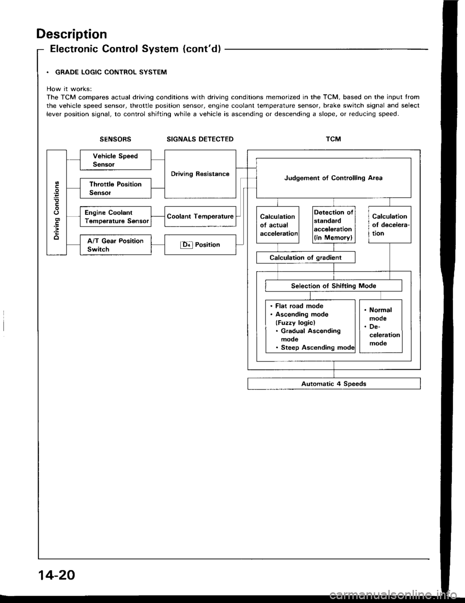
. GRADE LOGIC CONTROL SYSTEM
How it works:
The TCM compares actual driving conditions with driving conditions memorized in the TCM. based on the input trom
the vehicle speed sensor, throttle position sensor, engine coolant temperature sensor, brake switch signal and select
lever position signal, to control shifting while a vehicle is ascending or descending a slope. or reducing speed.
SIGNALS DETECTED
Dliving ResistanceJudgement of Controlling Area
Engine Coolant
TemDerature Sensor
. Flat road mode. Asconding mode
(Fuzzy logic). Gradual Ascending
mode. Steep Ascending
14-20
Page 437 of 1413
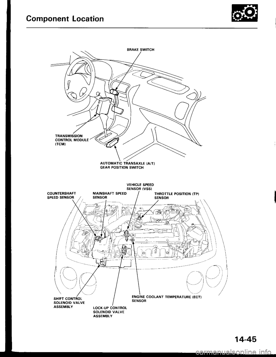
Component Location
)/
,/s\
{7v
A0t
AUTOMATIC TRANSAXLE IA/TIGEAR POSITION SWITCH
VEHICLE SPEEDSENSOR {VSSI
COUNTERSHAFTSPEED SEf{SORMAINSHAFT SPEEDSENSORTHROTTLE POSITION (TP}SENSOR
at
,
)''ENGINE COOLANT TEMPERATURE (ECTISENSOR
14-45
Page 443 of 1413
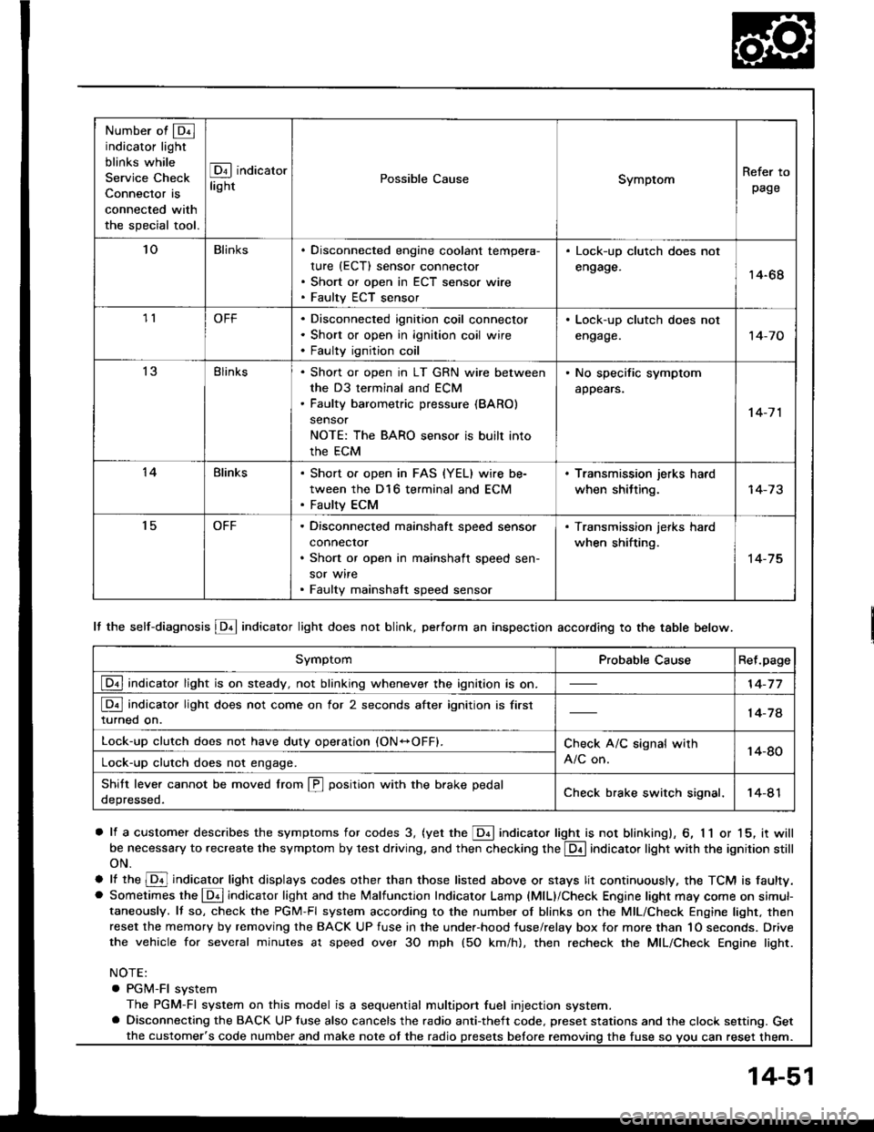
Number of @indicator light
blinks while
Service Check
Connector is
connected with
the special tool.
@ indicator
lightPossible CauseSymptomRefer to
page
'loBlinksDisconnected engine coolant tempera-
rure (ECT) sensor connector
Short or open in ECT sensor wire
Faulty ECT sensor
Lock-up clutch does not
engage.14-68
1lOFFDisconnected ignition coil connector
Short or open in ignition coil wire
Faulty ignition coil
. Lock-up clutch does not
engage.'t 4-7 0
13Blinks. Shon or open in LT GRN wire between
the D3 terminal and ECM. Faulty barometric pressure {BARO)
sensor
NOTE: The BARO sensor is built into
the ECM
. No specific symptom
appears.
14-7 1
14Blinks. Short of open in FAS {YEL} wire be-
tween the D16 terminal and ECM. Faulty ECM
. Transmission jerks hard
when shitting.
't5OFFDisconnected mainshaft speed sensor
connecror
Short or open in mainshaft speed sen-
sor wire
Faulty mainshaft speed sensor
. Transmission jerks hard
when shifting.
14-75
SymptomProbable CauseRet.page
LQ! indicator light is on steady, not blinking whenever the ignition is on.14-77
[Q3] indicator light does not come on for 2 seconds after ignition is first
turned on.14-78
Lock-up clutch does not have duty operation (ON-OFFI.Check A/C signal with
A/C on.14-80Lock-up clutch does not engage.
Shitt leve. cannot be moved lrom @ position with the brake pedal
depressed.Check brake switch signal,14-41
It the self-diagnosis LQ4 indicator light does not blink, perform an inspection according to the table below.
a lf a customer describes the symptoms for codes 3, (yet the LQ! indicator light is not blinkingl, 6, 1 1 or 15, it will
be necessa.y to recreate the symptom by test driving. and then checking the @ indicator light with the ignition still
oN.
e lt ttre @ indicator light displays codes olher than those listed above or stays lit continuously, the TCM is faulty.. Sometimes the Lqd indicator light and the Malfunction Indicator Lamp (MlL)/Check Engine light may come on simul-taneously. lf so, check the PGM-Fl system according to the numbe. of blinks on the MIL/Check Engine light. thenreset the memory by removing the BACK UP fuse in the unde.-hood fuse/relay box for more than 1O seconds. Drive
the vehicle for several minutes at speed over 30 mph (5O km/h), then recheck the MIL/Check Engine light.
NOTE:
. PGM-FI system
The PGM-Fl system on this model is a sequential multiport fuel injection system.a Disconnecting the BACK UP luse also cancels the radio anti-theft code. preset stations and the clock setting. Get
the fuse so vou can reset them.the customer's code number and make note ot the radio
14-51
Page 460 of 1413
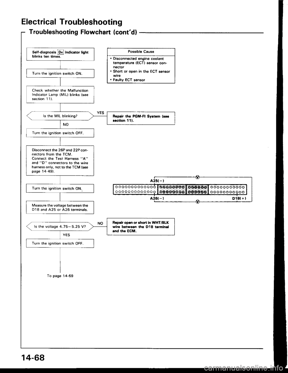
Electrical Troubleshooting
Troubleshooting Flowchart (cont'dl
Possibl€ Caus6
. Disconnoct€d engine coolantt€mp€rature (ECTI sensor con-noctor. Short or open in the ECT sensor
. Faulty ECT s€nsor
Self-diagnosis E indicator lightblinks ten times.
Turn the ignition switch ON.
Check whether the MalfunctionIndicator Lamp {MlL} blinks (seesection 1 1)-
ls the MIL blinking?Rop.ir tho PGM-FI Syrt.m (!go
!.ction 111.
Turn the ignition switch OFF.
Disconnectthe 26P and 22P con-nectors trom the TCM.Connect the Test Harness "A"
and "D" conneclors to the wireharness only, not to the TCM (seepage 14 49).
Measure the voltage between theD'18 and A25 or A26 lorminals.
Bopair op.n or .hofi In WHT/BLKwiro botwoon tho O18 tanni.|al.nd the ECM.ls the voltage 4.75-5.25 V?
Turn the ignition switch OFF.
oooooooooooo
ooooooooooooooooooooooo
oooo o oo o
Dlal + I
Page 1045 of 1413
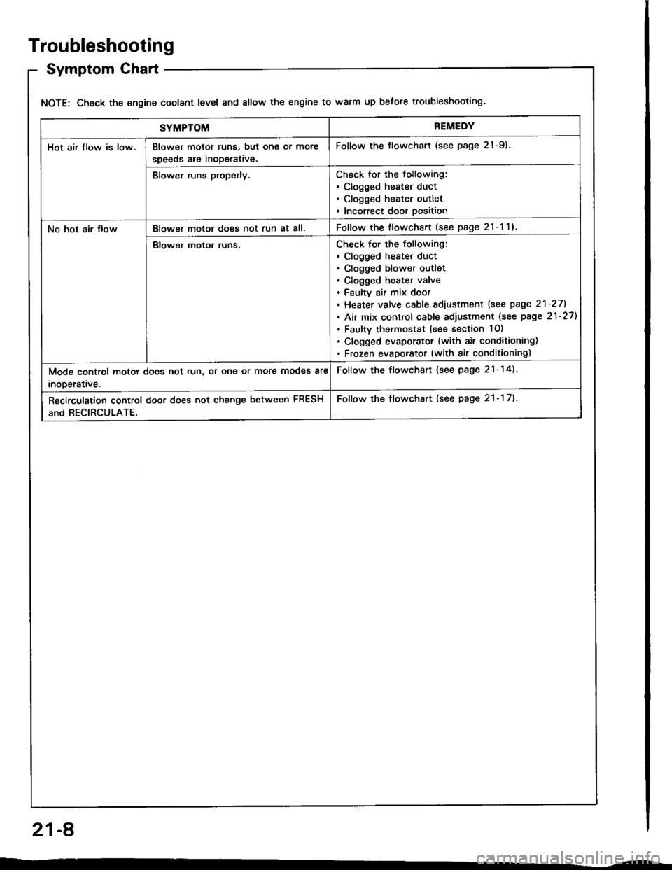
Troubleshooting
Symptom Chart
NOTE: Check the engine coolant level and allow the engine to warm up before troubleshooting.
SYMPTOMREMEDY
Hot air flow is low.Blower motor runs, but one ol more
speeds are inoperative.
Follow the tlowchart (see page 21-9).
Blower runs properly.Check for the following:. Clogged heater duct. Clogged heater outlet. Incorrect door position
No hot air JlowBlowel motor does not run at all.Follow the flowchart (see page 2l-l1l
Blower motor runs.Check for the following:. clogged heatet duct. Clogged blower outlet. Clogged heater valve. Faultv air mix door. Heater valve cable sdjustment lsee page 2'l-271
. Air mix control cable adjustment (see page 21-27)
. Faulty thermostat (see section lO)
. Clogged evaporator (with air conditioning). Frozen evaporator (with air conditioning)
Mode control motor does not run, or one or more modes are
inooerative.
Follow the flowchart (see page 21-14).
Recirculation control door does not change between FRESH
and RECIRCULATE.
Follow the flowchart (see page 21- 17).
21-A