engine coolant HONDA INTEGRA 1994 4.G Owner's Guide
[x] Cancel search | Manufacturer: HONDA, Model Year: 1994, Model line: INTEGRA, Model: HONDA INTEGRA 1994 4.GPages: 1413, PDF Size: 37.94 MB
Page 1059 of 1413
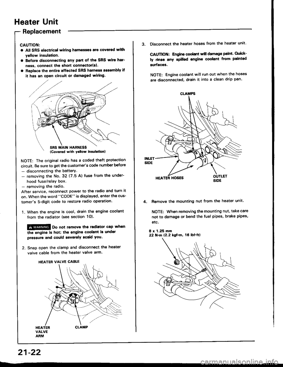
Heater Unit
Replacement
CAUTION:
a All SRS electrical witing hame$os are covoed wlth
yollow insulation.
a Before disconnecting any patt of tho SRS wito har-
neas, connect tha shott connoctol(s|.
a Roplaco th€ enlire sffacted SRS harnosr a$smbly if
it has an opon cilcult or dsmaged wiring.
NOTE: The original radio h8s a coded theft protection
circuit. Be sure to get the customer's code number betors
- disconnecting the bafterY.
- removing the No. 32 (7.5 A) fuse from th€ under-
hood tuse/relav box.- removing the radio
After service. teconnect power to the radio and turn it
on, when the word "CODE" is displayed, enter the cus-
tomer's 5-digit code to restore radio operation.
1. When the engine is cool, dtain the engine coolant
from the radiator (see section 1O).
@@ oo not lomove tho radiator cap whan
the ongine is hol; tha ongino coolant is undot
pressure and could a€voralY tcald you.
2. Snap open the clamp and disconnect the heater
valve cable from the heater valve arm.
HEATER VALVE CABLE
21-22
CLAMFS
3. Disconnect the heater hoses from the heater unit'
CAUTIOII: Engino coobnt will damago paint. orick-
ly dnse any rpilled engine coolant from paintod
surfac63.
NOTE: Engine coolant will tun out when the hoses
are disconnected, drain it into a clean drip pan'
HEATER HOSES
Remove the mounting nut from the heater unit.
NOTE: When removing the mounting nut, take care
not to damage or bend the fuel pipes, brake pipes,
etc.
8 r 1,25 rn|n22 N.m 12.2 kgt.m, tO lbf'ftl
4.
Page 1060 of 1413
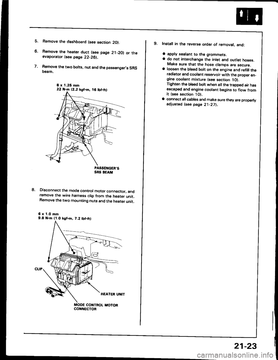
5.
6.
7.
Rsmove the dashboard (see section 2O).
Remove the heater duct (see page 21-20) or theevaporator lse€ page 22-26).
Rsmove the two bolts, nut and the passenger,s SRS(}eam.
PASSEIVGER'SSRS EEAM
Disconnect the mode control motor conngctor, andremove the wire harness clip from the h€8ter unit.Remove the two mounting nuts and the haater unit.
6 r 1.0 mm9.8 .m (l.O kgt.m, 7.2 tbt.frl
MODE COI{TROL I,IOTORcol{t{€cToF
8.
8 x 1,26 mln22 N.m 12.2 kgf.m, 18 tbt.ttl
9. Install in the reverse order of removal, and:
a apply sealant to the grommets.a do not int6rchange the inlet and outl€t hoses.Make sure that the hose clamps are secure.a loosen th€ ble6d bolt on th6 engine and r€fillthetadiator and coolant r€servoir with the propsr en_gine coolant mixture (sse section 1O).Tighten the blsed boh when all the trapped air has6sc8p6d and engine coolant begins to flow fromit (see section 1O).a connect all csbles and make sure they 8re properlyadiusted (see pdge 21-271.
21-23
Page 1107 of 1413

Electrical
Special Tools
Troubleshooting
Tips and Precautions ................................ 23-3Five-stop Tloubleshooting ..............,...-..-... Z3-sSchematic Symbols ................................_. 23-6wire Color Cod€s ..................................... 23-6Relay and Control Unit Locations
Engine Compartment .........,............ ... --. 23-7Dsshboard and Door ..,,......................... 23-gDashboard and Floor ............................. 23-t OOuaner Panel .....-.....23-12Connector ldentification and WireHarness Routing ........ 23-i 3
Index to Circuits and Systems
Airbag ............... ...-..-... 2g-26sAir Conditioning ....,.. Section 2lAltelnator ......_.............. 23-99Anti-lock Brake Systsm (ABS) Section 19Automatic Transmission Section 14Battery .............. .......... 23-66Chafging System ........... 23-98rCigalstte Lighter .....................-...-......-..-.. Z3-2O4Cfock ................. ..........23-197rcruise Controf .......--..-... 23-242Distributor .................... 23-87Fan Controls ................. 23-1ogFuel and Emissions ... Section 1i*Fuses
Under-dash Fuse/Relay Box ................... 23-48Undor-hood ABS Fuse/Retay Box ............ 23-51Under-hood Fuse/Relay Box,.................. 23-52rGauges
Engine Coolant Temperature {ECT)Gauge ................ ..23-126Fuef cauge ............... 2g-123'Gauge Assembly ....--.23-113Speedometer .....-...,,. 23-114Tachometer .....,.....-.. 23-114Ground Distribution ........ 23-60Heater ,,,........,.... ..... Section 2lrHorn ................. ........... 23-199*fgnition Switch ............. 23-70fgnition Syst6m .......-..-.. 23-A7lgnition Timing .............. 23-89Indicator Lights"A/T Gear Position .............. ................... 23-1 32B1ak6 System ...,..,..-.23-127Engine Oil Pressura .............................. _ 23-1 51Low Fuel ............ ......23-125Malfunction Indicator Lamp {MlL} ...,,. Section I l
tfnteglated Control Unit ...29-144*lnterlock System ...................................... 23-1 3gLights, Exteriol
Back-up Lights ........... 23-179Brake Lights .............. 23-t8ltDaytime Running Lights {Csnada} ........... 23-156Front Palking Lights ............................. 23-1 65Flont Side Marker Lights ....................... 23-165Front Turn Signal Lights ........................ 23-1 65*Hazard Warning Lights .........................- 2g-1A4Headlights ................. 23-t6tLicense Plate Lights .............................. 23-1 69Taillights(Harchback) .......... 23-166
{Sedan) .............. .. 23-167Lights. Inteliol
Cargo Area Light {Hatchback) ...... -.. -.. -... 23-177Ceifing Light ........-..-.23-175
Dash Lights Blightness Controt .............. 23-t70Glove Box Lighr ................................... 23-1 69Spotfighr ............ ....-.23-174Trunk Light (Sedanl ............... .............. - 23.-177*Lighting Sysrem .......-.-... 23-152:Moonroof ,,.,.......,..,,,,,.-.23-211PGM-FI Systom ........ S€crion 11Power Distribution .,.-..--..23-54Power Door Locks .............,,..................... 23-233Power Mirors ..,..,....-...- 23-216Power Relays ...........,..... 23-68Power Windows ............ 29-222*Rear Window Defogger ........,... ..........,..... - 23-20,6Reminder Systems
Key-in Remindel System ....,.............,.... 23-1 50Lights-on Reminder System ................... 23-l 5f*Maintenance Reminder system ..,,.... -.. - -. 23-.1 2gSeat Belt Reminder System ..................- 23-125*Side Markel/Turn Signal/Hazard
Ffasher System .,..,..-.23.-1A4Spark Pfugs .........-...-..... 23-97Starting System ....,,.....-. 23-73*Stereo Sound System ...,.......................,,.. 23-l gg
Supplemental Restraint System {SRS} ......... 23-265Vehicfe Speed Sensor {VSS) .............--..-.... 23-122*Wiper/Washer Systom ...............--.........-..- Zg-254
rRead SRS pi€cautions on Page 23-271 betore workingin these areas.
-+
Page 1122 of 1413
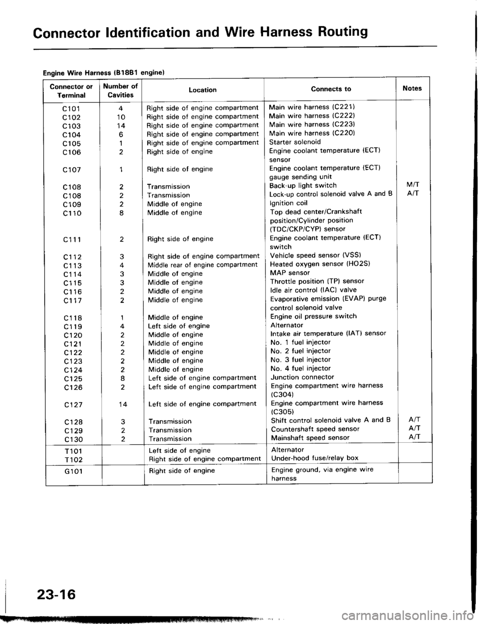
Gonnector ldentification and Wire Harness Routing
Engine Wire Harness {B1881engine)
Connector 01
Terminal
Number of
CavitiesLocationConnects ioNotes
c10'l
c102
c103
c104
c 105
c106
c107
c108
c108
c109
c110
c111
c113
c114
c115
Lt to
c117
c118
c119
c't 20
c121
c122
c123
cl24
c125
c't26
c127
c128
c129
c130
10
14
6
1
1
2
2
8
2
3
t
1
2
2)
2
8
14
2
2
Right side of engine compartment
Right side of engine compartment
Right side of engine compartment
Right side ol engine compartment
Right side of engine compartment
Right side of engine
Right side ol engine
Transmission
Transmission
Middle of engine
lvliddle of engine
Right side ot engine
Right side of engine compartment
ldiddle rear of engine compartment
Middle of engine
Middle ol engine
Middle of engine
Middle of engine
Middle ot engine
Left side of engine
lvliddle of engine
Middle of engine
Middle of engine
Middle ot engine
Middle ol engine
Left side of engine compartment
Left side of engine compartment
Left side of engine compartment
Transmission
Transmission
Transmission
Main wire harness (C221)
Main wire harness {C222}
Main wire harness (C223)
Main wire harness {C220)
Starter solenoid
Engine coolant temperature {ECT)
sensor
Engine coolant temperature (ECT)
gauge sending unit
Back'up light switch
Lock-up control solenoid valve A and B
lgnition coil
Top dead center/Crankshaft
position/Cylinder position
(TDC/CKP/CYP) sensor
Engine coolant temperature (ECT)
switch
Vehicle speed sensor (VSS)
Heated oxygen sensor (HO2S)
MAP sensor
Throttle position (TP) sensor
ldle air control (lAC) valve
Evaporative emission (EVAPI purge
control solenoid valve
Engine oil pressure switch
Alternator
Intake air temperature {lAT} sensor
No. 'l fuel injector
No. 2 tuel injector
No. 3 fuel injector
No. 4 fuel injector
Junction connector
Engine compartment wire harness
(c304)
Engine compartmenl wire harness
(c305)
Shift control solenoid valve A and B
Countershait speed sensor
Mainshaft speed sensor
M/T
NT
NT
NT
T 101
r102
Lelt side oI engine
Right side of engine compartment
Alternator
Under-hood tuse/relay box
G 101Right side of engineEngine ground, via engine wire
harness
23-16
Page 1124 of 1413
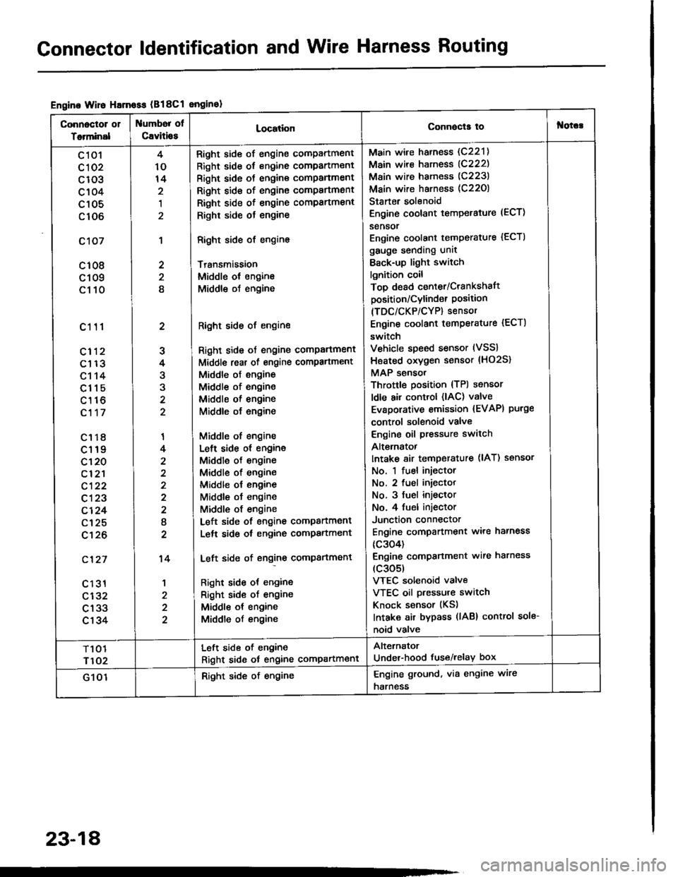
Gonnector ldentification and Wire Harness Routing
Engine Wire Harnoss (B18Cl enginol
Connoctor 01
Totminal
umbor ol
Cavitio8LocationConnecla tof{orc!
c 101
cl 02
c103
c104
c105
c106
c107
c108
c109
c110
c111
cl12
c113
c114
c115
c116
c117
c1r8
c119
c120
cl2'l
c122
c123
c124
c125
c't26
c'127
c 131
c132
c133
c134
2
J
4
3
'I
4
2
I
2
't4
1
4
10
14
,l
2
2
8
Right side of engine compartment
Right side of engine compartment
Right side ot engine comPanment
Right side of engine compartmsnt
Right side of engine compartment
Righr side ot engine
Right side of engine
Transmission
Middle ol engine
Middle oJ engine
Right side of engine
Right side ot engine comPartment
Middl€ reat of engine compartment
Middle of engine
Middle of engine
Middle ol engine
Middle o{ engine
Middle of engine
Lelt side ot engine
Middle of engine
Middle of engine
Middle ol engine
Middle ot engine
Middle of engine
Left side of engine companment
Lelt side ot engine compartment
Left side of engine compartment
Right side ot engine
Right sid€ of engine
Middle ot engine
Middle of engine
Main wire harness (C221)
Main wire harness (C222)
Main wire harness (C223)
Main wire harness (C22O)
Starter solenoid
Engine coolant temperature (ECT)
sensor
Engine coolant temperature {ECTI
gauge sending unit
Back-up light switch
lgnition coil
Top dead center/Crankshaft
position/Cylind€r Position(TDC/CKP/CYP) sensor
Engine coolant temperature {ECT)
switch
Vehicle speed sensor (VSS)
Hsated oxygen sensor {HO2S}
MAP sensor
Throttle position {TPl sensor
ldle air control (lAC) valve
Evaporative emission {EVAPI purge
control solenoid valve
Engine oil pressure switch
Alt€rnatot
Intake 8ir temperature (lAT) ssnsor
No. 1 fuel injector
No. 2 fuel iniector
No. 3 fuel injeclor
No. 4 fuel injector
Junction connector
Engine compartment ware harness
{c304)
Engine comPanment wire harness
(c305)
VTEC solenoid valve
VTEC oil pressure switch
Knock sensor (KS)
Intaka air bypass (lAB) control sole-
noid valve
T101
r102
Left side of engine
Right sid6 ot engine compartment
Alternator
Under-hood fuse/relay box
G 101Right side of engineEngine ground, via engine wire
harness
23-18
Page 1218 of 1413
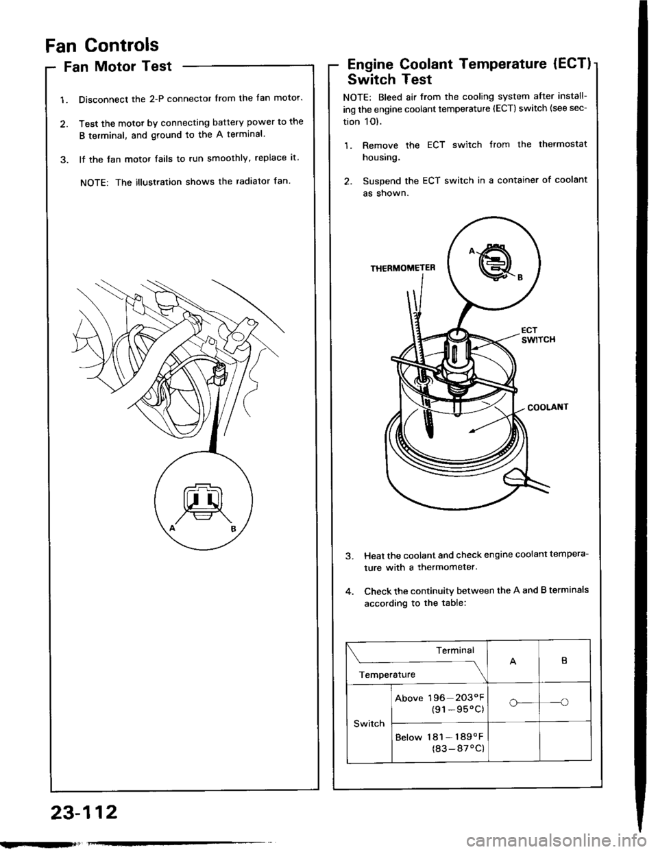
Fan Controls
Fan Motor Test
1. Disconnect the 2-P connector from the fan motor.
2. Test the motot by connecting battery power to the
B terminal, and ground to the A terminal
3. lf the Jan motor fails to run smoothly, replace it.
NOTE: The illustration shows the radiator fan.
Engine Coolant Temperature (ECT)
Switch Test
NOTE: Bleed air from the cooling system atter install-
ing the engine coolant temperature (ECT) switch (see sec-
tion 1O).
1. Remove the ECT switch from the thermostat
housing.
2. Suspend the ECT switch in a container of coolant
as shown.
Heat the coolant and check engine coolanl tempera-
ture with a thermometer.
Check the continuity between the A and B terminals
according to the table:
Terminal
;;,".,"---\
B
Switch
Above 196 2O3"F
{91-95'C)o_-o
Below 181- 189oF
(83-87'C)
23-112
Page 1219 of 1413
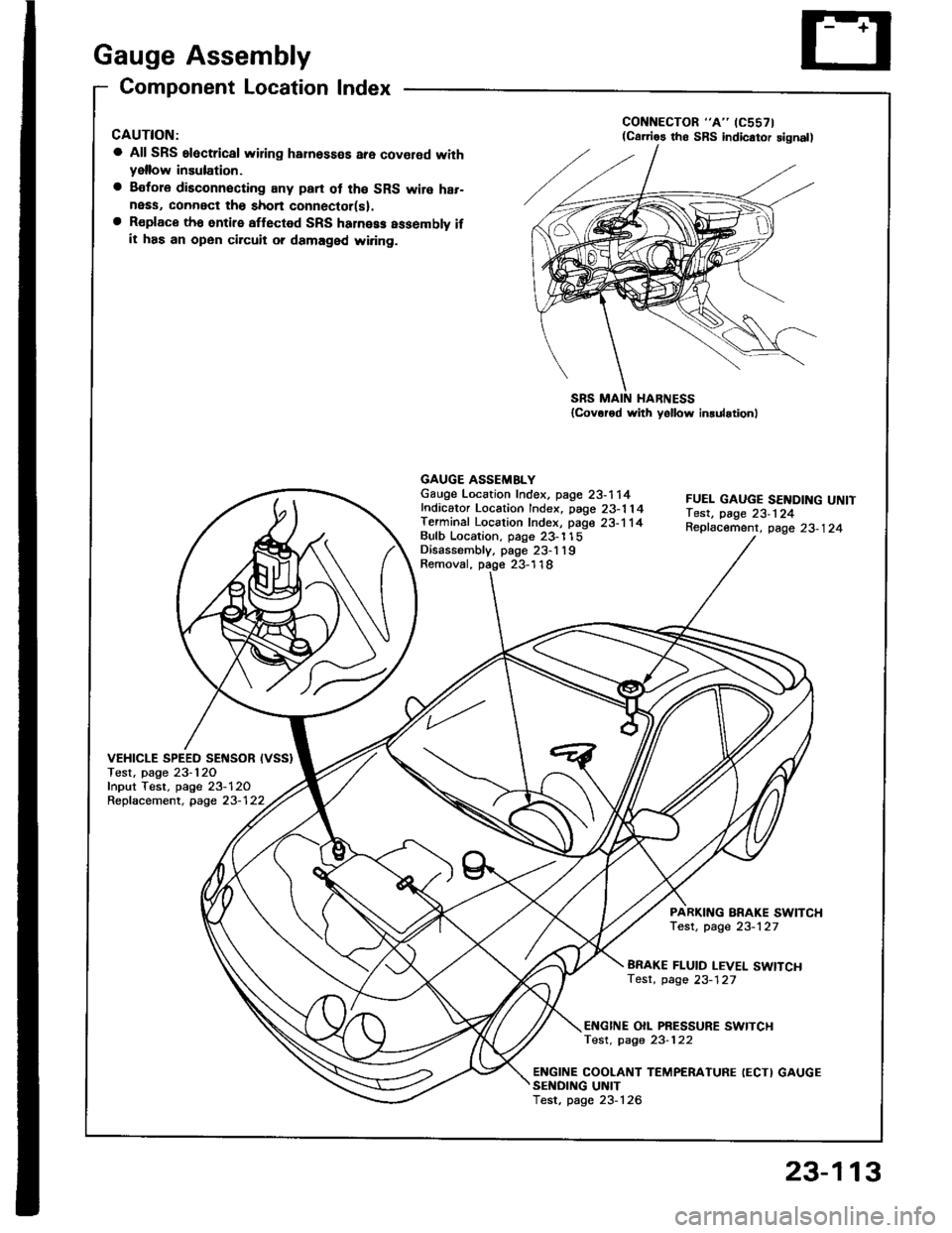
Gauge Assembly
Component Location Index
CAUTION:
a All SRS electrical wiring harnosses are cov€rod withyellow insulation.
a Bofore disconnecting any prn ot th€ SRS wire har-ness, connect tho short connector(sl.a R€place th6 entirs affGcted SRS halne$ assembly ifit has an open circuit o? damaged wiring.
SRS MAIN HARNESS{Cov.r6d with yollow inrularionl
GAUGE ASSEMBLYGauge Location Index, page 23-114Indicator Location Index, page 23-1 14Terminal Location Index, page 23-114Bulb Location. page 23-'l 15Disassembly. page 23-1 19Removal, page 23-118
FUEL GAUGE SENDING UNtTTest, page 23'124Repfacemenr, page 23-124
VEHICLE SPEEO SENSOB IVSS}Test, page 23-120fnput Test. page 23-120Repfacement, page 23-122
PARKITTG BRAKE SWITCHTest, page 23-127
BRAKE FLUID LEVEL SWITCHTesr, page 23-127
EI{GINE OIL PBESSURE SWITCHTest, page 23-122
ENGINE COOLANT TEMPERATURE IECTI GAUGESENOING UNITTest, page 23-126
(C61'ios tho SBS indicator signal)
23-113
Page 1232 of 1413
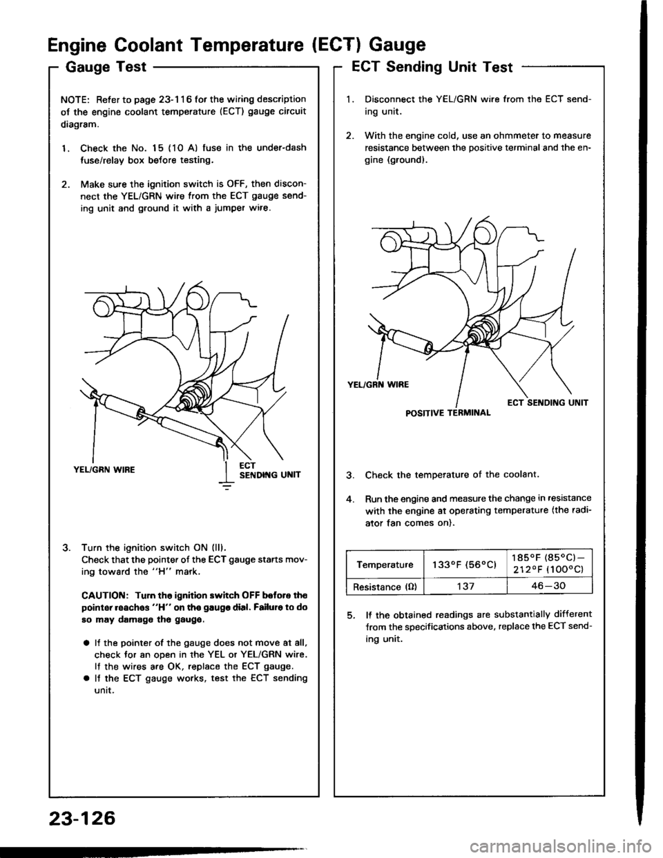
GaugeTest
NOTE: Refer to page 23-116 fot the wiring description
oJ the engine coolant temperature (ECT) gauge circuit
diagram.
1. Check the No. 15 (10 A) fuse in the under-dash
tuse/relay box before testing.
2. Make sure the ignition switch is OFF, then discon-
nect the YEL/GRN wire from the ECT gauge send-
ing unit and g.ound it with a jumper wire.
Turn the ignition switch ON (lll.
Check that the pointer of the ECT gauge starts mov-
ing toward the "H" mark,
CAUTION: Tuln th6 ignition switch OFF botore th€
point reaches "H" on tho gaugo dial. Failuro to do
so may damago tho gaugo.
a It the pointer of the gauge does not move at all,
check Jor an oDen in rhe YEL or YEL/GRN wire.
lf the wires are OK, replsce the ECT gauge.
a It the ECT gauge works, test the ECT sending
untt.
J.
Engine Coolant Temperature (ECTI Gauge
ECT Sending Unit Test
Disconnect the YEL/GRN wire from the ECT send-
ing unit.
With the engine cold, use an ohmmeter to measure
resistance between the positive terminal and the en-
gine (ground).
Check the temperature of the coolant.
Run the engine and measure the change in ,esistance
with the engine ai operating temperatu.e {the radi-
ator tan comes on).
5. ll the obtained readings are substantially different
Jrom the specifications above, replace the ECT send-
ing unit.
23-126
POSITIVE TERMINAL
Temperatu.e1330F (560C)185.F (850C)-
2120F (1000c)
Resistance (O)'t3746-30